Sindoh D310 Series Quick Installation Manual
Hide thumbs
Also See for D310 Series:
- User manual (70 pages) ,
- User manual (8 pages) ,
- User manual (324 pages)
Table of Contents
Advertisement
Quick Links
Advertisement
Table of Contents

Subscribe to Our Youtube Channel
Related Manuals for Sindoh D310 Series


Summary of Contents for Sindoh D310 Series
- Page 1 D310 Series Quick Installation Guide...
-
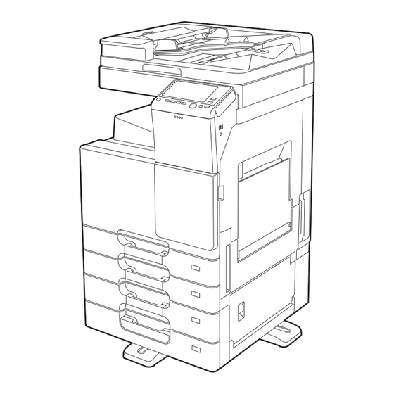
Page 2: Overview Of Installation Procedure
If you do not follow the procedure in order, the image trouble may occur. 1. Overview of Installation Procedure <D310 Series> When installing the main body and associated options as a system, follow the order shown on the upper. Warning - Lifting the main body in an awkward position or transporting it in a poorly balanced position could result in personal injury. -
Page 3: Accessory Parts
2. Installation space (unit: mm) Avoid a dusty location, or a place near volatile and flammable substances. D310 Series + DF-628 + PC-214 + MK-603 + Avoid a poorly ventilated place. RU-14 + FS-534 + SD-511 + MK-748 + CU-101 4. - Page 4 * Power supply: 120V 12A, 220-240V 8A Note - This manual provides the illustrations of Refer to the installation manual for the Paper the accessory parts and machine that may Feed Cabinet (or the Desk) and follow the be slightly different in shape from yours. “Installation Procedures.”...
- Page 5 Remove the protective sheet as shown in the illustration. Move the fusing adjustment lever down to the printing position (bottom). Open the right door and remove the locking materials. Note - After removing the locking materials, make sure that the transfer roller assy is Close the right door.
- Page 6 Remove the protective tape from the inside of Affix the supplied blank label. the tray 1 and remove accessory parts. Open the front door. Slide out the tray 2. Remove the protective tape from the inside of the tray 2 and remove accessory parts. Remove the protective tape.
-
Page 7: Installing The Toner Cartridge
8. Installing the toner cartridge Release the lever of the drum unit (K). Note - Since a toner cartridge is not supplied with the machine, purchase one (of different colors) separately. Shake the toner cartridge up and down and left to right 5 to 10 times respectively. Note - Shake the cartridge adequately. -
Page 8: Installing Other Options
Push the toner cartridge all the way in and Attach the supplied connector cover to the rotate it clockwise to lock it. machine. (One supplied screw) Note - Make sure that the toner cartridge is pushed all the way in. Attach the supplied duct cover. - Page 9 14. Serial number input Plug the power cord into the power outlet. Note - Serial number input is, if necessary, needed only for the optional devices installed in “9. Installing other options.” Touch the item you want to enter and input the serial number.
-
Page 10: Configuring Other Options
17. Configuring other options Open fully the reverse automatic document feeder or the original cover if loaded. If any of the following options are installed, refer to the “Configuration procedures” of the Note installation manual for each option and - Do NOT place a document on the configure the option(s). -
Page 11: Network Setting
Check LEDs for lighting conditions. Touch “OK” after the “TCP/IP Settings” - LED1 : Should light up steadily if the link screen is displayed. network connection has been made. - LED2 : Should blink according to the Select the function to be used as follows: communications status of the ACT Forward → Forward → Detail Settings →... -
Page 12: Affixing The Panel Sheet
22. Affixing the paper size label Affix the paper size labels that correspond to the sizes of paper used in each tray. See the User’s Guide CD for instructions on 24. Affixing the panel sheet setting paper in each tray and configuring the paper types. -
Page 13: Installation Procedures
OC-514 Original Cover 2. Installation procedures INSTALLATION MANUAL Remove the two knockouts using nippers or a similar tool. 1.Accessory parts Name Shape Q’ty Original cover Original mat Hinge cover Attach the supplied hinge cover (right) and (right) hinge cover (left). (Two screws supplied with the original cover) Hinge cover (left) - Page 14 Using a cleaning pad dampened with alcohol, Gently press the original cover. wipe the undersurface of the original cover, where the original mat is attached. Open the original cover and press on the With the double-sided tape facing up, original mat firmly so that it does not peel off. position the original mat on the original glass.
- Page 15 ■ Memo...
- Page 16 A797-9714-00 *A7979714* Printed in China...
Need help?
Do you have a question about the D310 Series and is the answer not in the manual?
Questions and answers