
Related Manuals for Avigilon 2.0C-H6SL-BO1-IR


Summary of Contents for Avigilon 2.0C-H6SL-BO1-IR
- Page 1 Installation Guide Avigilon H6SL Camera Models: 2.0C-H6SL-BO1-IR 3.0C-H6SL-BO1-IR 3.0C-H6SL-BO2-IR 5.0C-H6SL-BO1-IR 5.0C-H6SL-BO2-IR...
- Page 2 © 2023, Avigilon Corporation. All rights reserved. AVIGILON, the AVIGILON logo, AVIGILON CONTROL CENTER, and ACC are trademarks of Avigilon Corporation. Other names or logos mentioned herein may be the trademarks of their respective owners. The absence of the symbols ™ and ® in proximity to each trademark in this document or at all is not a disclaimer of ownership of the related trademark.
- Page 3 (such as from a liquid spill or fallen objects), has been exposed to rain or moisture, does not operate normally, or has been dropped. Do not use strong or abrasive detergents when cleaning the device body. Use only accessories recommended by Avigilon. This device complies with EN 60529 IP66 and IP67 ratings.
- Page 4 Consult the dealer or an experienced radio/TV technician for help. Changes or modifications made to this equipment not expressly approved by Avigilon Corporation or parties authorized by Avigilon Corporation could void the user’s authority to operate this equipment. To meet the requirements of the EN 50121-4 Railway Applications Standard, use an external power supply or POE injector that is also compliant with EN 50121-4.
- Page 5 IR Safety Information Use appropriate shielding or eye protection. Disposal and Recycling Information When this product has reached the end of its useful life, please dispose of it according to your local environmental laws and guidelines. European Union: This symbol means that according to local laws and regulations your product should be disposed of separately from household waste.
-
Page 6: Table Of Contents
Table of Contents Overview Junction Box View Front View Side View Rear View Configuration Panel View Installation Camera Package Contents Installation Steps Mounting the Bullet Camera Removing the Configuration Panel Cover Initializing a Camera Username and Password (Optional) Using the USB Wi-Fi Adapter Assigning an IP Address Setting the IP Address Using the ARP/Ping Method Accessing the Live Video Stream... -
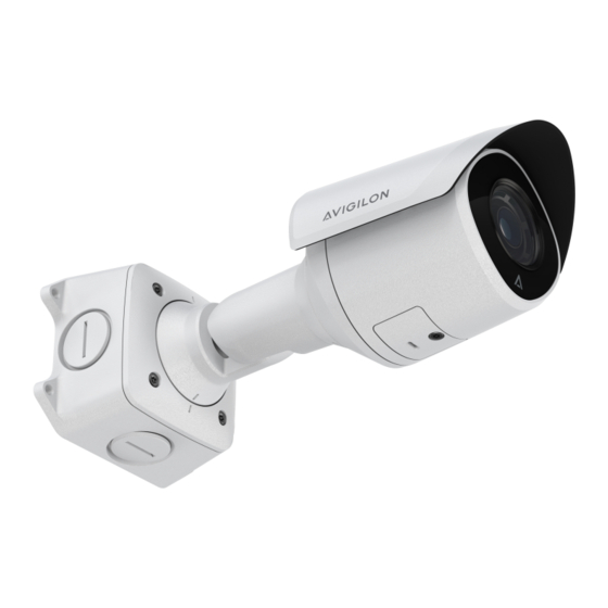
Page 7: Overview
Overview Junction Box View 1. Camera mounts Points for installing the camera to the junction box. 2. Mounting hook slots Points to hold the camera to the junction box while connecting the required cables. 3. Mounting holes Holes for securing the junction box to the mounting surface. Front View 1. -
Page 8: Side View
Side View 1. Sun shroud An adjustable cover to help protect the lens against glare from the sun. 2. Mount arm Adjustable mount arm for positioning the camera. 3. Adjustment screws Provides a locking mechanism for the mount arm. Rear View 1. -
Page 9: Configuration Panel View
Configuration Panel View 1. microSD card slot Accepts a microSD card for onboard storage. For more information, see (Optional) Configuring microSD Card Storage on page 19. 2. Micro USB port Accepts a micro USB to USB adapter. Only required when using the USB Wi-Fi Adapter. 3. -
Page 10: Installation
Installation Camera Package Contents Avigilon H6SL Bullet Camera Junction box Mounting template sticker 4 screws and anchors for solid walls 4 screws for attachment to electrical box Protective rubber boot for Ethernet port Teflon tape Installation Steps Complete the following sections to install the device. - Page 11 3. Fasten the junction box to the mounting surface. Note: To prevent moisture from entering the junction box, it is recommended to apply teflon tape around the threaded conduit pipe at the cable entry point of the junction box. Ensure the other two conduit plugs are fully tightened.
- Page 12 Note: Before connecting any cables, ensure that the cable connections are properly protected from moisture and corrosion. Make sure the protective cable boot is installed over the Ethernet port to protect the connection from dust and moisture. If PoE is not available, the camera may be powered through the auxiliary power cable using either 12 VDC.
- Page 13 7. Connect the network cable to the camera's Ethernet port. 8. Tuck the extra lengths of cables into the cable entry hole or within the junction box compartment. 9. Raise the camera until it covers the junction box. Mounting the Bullet Camera...
-
Page 14: Removing The Configuration Panel Cover
10. Use the camera mounting screws to fasten the camera to the junction box. Removing the Configuration Panel Cover 1. Use a T20 Pin-In star-shaped driver to unscrew the configuration panel cover. 2. Remove the cover from the configuration panel. Removing the Configuration Panel Cover... -
Page 15: Initializing A Camera Username And Password
For more information, see the Avigilon Cloud Services User Guide. Tip: If you are connecting your Avigilon camera to a 3rd party VMS, you will need to set up the first user through the camera's Web Interface or Camera Configuration Tool before you connect to the 3rd party VMS. -
Page 16: Assigning An Ip Address
USB Wi-Fi Adapter on the previous page. Device's web browser interface: http://<camera IP address>/. Network Video Management software application (for example, the Avigilon Control Center™ software). ARP/Ping method. For more information, see Setting the IP Address Using the ARP/Ping Method below. -
Page 17: Accessing The Live Video Stream
The mobile web interface using the USB WiFi Adapter. For more information, see (Optional) Using the USB Wi-Fi Adapter on page 15. Web browser interface: http://< camera IP address>/. Network Video Management software application (for example, the Avigilon Control Center software). Accessing the Live Video Stream... -
Page 18: Aiming The Camera
Aiming the Camera Reference the camera's live stream as you aim the camera. 1. Loosen the adjustment screw closest to the junction box to rotate the camera arm. 2. Loosen the center adjustment screw to tilt the camera. 3. Loosen the adjustment screw on the camera to turn the camera body. Aiming the Camera... -
Page 19: Zooming And Focusing The Camera
Zooming and Focusing the Camera In the camera web browser interface or the Avigilon Control Center software, use the camera’s Image and Display settings to zoom and focus the camera. -
Page 20: Configuring The Camera
For more information, see the Camera Configuration Tool User Guide. If the camera is connected to the Avigilon Control Center system, you can use the client software to configure the camera. For more information, see the Avigilon Control Center Client User Guide. -
Page 21: Connecting To External Devices
Connecting to External Devices External devices are connected to the camera through the power and I/O wires. For the locations of the I/O connector block, see Overview on page 7. The pinout for the I/O is shown in the following diagram. Figure 1: Example application. -
Page 22: Connection Status Led Indicator
Connected to the Network Video Management software or an ACC™ Server. The default connected setting can be changed to Off using the camera's web user interface. For more information see the Avigilon IP Camera Web Interface User Guide. Troubleshooting Network Connections and LED Behavior Note: For any of the below LED behaviors, ensure that the camera is getting power and is using a good network cable before trying another solution. - Page 23 LED Behavior Suggested Solution Both LEDs are blinking several times at Perform a factory reset of the camera using the physical the same time, then pause and repeat the firmware revert button. Resetting through the camera's web blinking interface will not produce the desired result. A different LED blinking pattern than Perform a factory reset of the camera using the physical those described above...
-
Page 24: Resetting To Factory Default Settings
Resetting to Factory Default Settings If the device no longer functions as expected, you can choose to reset the device to its factory default settings. Use the firmware revert button to reset the device. The firmware revert button is shown in the following diagram: Figure 2: The firmware revert button in the Configuration Panel. -
Page 25: For More Information
Additional information about setting up and using the device is available in the following guides: Avigilon Control Center Client User Guide Avigilon IP Camera Web Interface User Guide Camera Configuration Tool User Guide Designing a Site with Avigilon Video Analytics These guides are available on help.avigilon.com... -
Page 26: Limited Warranty And Technical Support
Limited Warranty and Technical Support Avigilon warranty terms for this product are provided at avigilon.com/warranty. Warranty service and technical support can be obtained by contacting Avigilon Technical Support: avigilon.com/contact. Limited Warranty and Technical Support...
Need help?
Do you have a question about the 2.0C-H6SL-BO1-IR and is the answer not in the manual?
Questions and answers