
Related Manuals for Avigilon H5A-PTZ


Summary of Contents for Avigilon H5A-PTZ
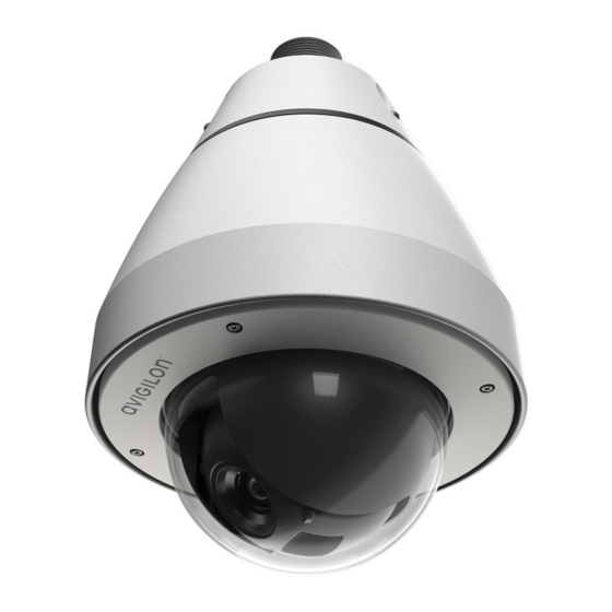
- Page 1 Installation Guide Avigilon H5A-PTZ Camera Models: 2.0C-H5A-PTZ-DP36 2.0C-H5A-PTZ-DC36 4.0C-H5A-PTZ-DP36 4.0C-H5A-PTZ-DC36 8.0C-H5A-PTZ-DP36 8.0C-H5A-PTZ-DC36...
- Page 2 Refer all device servicing to qualified personnel. Servicing may be required when the device has been damaged (such as from a liquid spill or fallen objects), does not operate normally, or has been dropped. Do not use strong or abrasive detergents when cleaning the device body. Use only accessories recommended by Avigilon.
- Page 3 Consult the dealer or an experienced radio/TV technician for help. Changes or modifications made to this equipment not expressly approved by Avigilon Corporation or parties authorized by Avigilon Corporation could void the user’s authority to operate this equipment. Disposal and Recycling Information When this product has reached the end of its useful life, please dispose of it according to your local environmental laws and guidelines.
- Page 4 (2) is responsible for your use of, or reliance on, the information. Avigilon Corporation shall not be responsible for any losses or damages (including consequential damages) caused by reliance on the information presented herein.
-
Page 5: Table Of Contents
Table of Contents Overview Bottom View - Pendant Bottom View - In-Ceiling Bottom View - LEDs Top View Dome Cover Pendant Wall Mount View NPT Mount View In-Ceiling Mount Installation Camera Package Contents Retrofitting an In-Ceiling H4 PTZ Installation Steps Preparing the Camera for Installation Cutting the Mounting Hole Connecting Cables... - Page 6 Configuring the Camera Setting the Home Preset Position Manually Returning to the Home Position Automatically Returning to the Home Position Connection Status LED Indicator Troubleshooting Network Connections and LED Behavior Resetting to Factory Default Settings Setting the IP Address Using the ARP/Ping Method Cleaning Dome Bubble Body...
-
Page 7: Overview
Overview Bottom View - Pendant 1. microSD card slots (x2) Accepts up to two microSD cards for onboard storage. Install microSD cards so the metal contacts are facing inward. For more information, see (Optional) Configuring Onboard Storage on page 31. 2. Lens The camera lens is housed behind a protective window. -
Page 8: Bottom View - In-Ceiling
Bottom View - In-Ceiling 1. microSD card slots (x2) Accepts up to two microSD cards for onboard storage. Install microSD cards so the metal contacts are facing inward. For more information, see (Optional) Configuring Onboard Storage on page 31. 2. Clamps Spring loaded locking mechanisms that secure the camera to the mounting surface. -
Page 9: Bottom View - Leds
Bottom View - LEDs 1. Connection status LED indicator Green LED provides information about device operation. For more information, see Connection Status LED Indicator on page 35. 2. Link LED indicator Amber LED indicates if there is an active connection in the Ethernet port. Note: The camera LEDs will flash and provide status information when the camera is establishing a network connection. -
Page 10: Top View
Top View 1. Lanyard anchor (Pendant camera only) The safety lanyard attaches to the anchor to prevent the camera from falling during installation. 2. Ethernet port Accepts an Ethernet connection to a network. Server communication and image data transmission occurs over this connection. Also receives power when it is connected to a network that provides Power over Ethernet. -
Page 11: Dome Cover
Dome Cover 1. Dome cover Vandal resistant dome cover. 2. Tamper resistant screws Star-shaped captive screws to fix the dome cover to the base. Dome Cover... -
Page 12: Pendant Wall Mount View
Pendant Wall Mount View 1. Pendant wall mount Camera mount for walls and other mounting surfaces. 2. Lanyard Connects to the lanyard anchor on the camera base. 3. Tamper resistant screws Star captive screws to fix the dome camera to the mounting adapter. 4. -
Page 13: Npt Mount View
1. 1-1/2” NPT-female to NPT-female adapter An adapter for attaching the pendant NPT mount to an NPT pipe. Note: The 1-1/2" NPT-female to NPT-female adapter is not supplied or sold by Avigilon and should be sourced separately. 2. Lock nut Locking nut for securing the pendant NPT mount on the NPT-female to NPT-female adapter. -
Page 14: In-Ceiling Mount Installation
The Avigilon H5A-PTZ In-Ceiling camera provides easy retrofitting with Avigilon H4 PTZ In-Ceiling camera installations. The following options are available to easily swap a new H5A-PTZ with an installed H4 PTZ: Re-uses the original mounting location. The H5A-PTZ is designed to install into the same mounting location as the H4 PTZ. - Page 15 1. Place the camera on a flat surface with the dome facing up. 2. Use the T20 star key to loosen the 4 tamper resistant screws and then remove the dome cover. 3. Remove the protective foam material inside the dome cover. Remove the plastic protective film from the inside of the dome cover.
-
Page 16: Cutting The Mounting Hole
5. Use a screw driver to push each of the clamps into the dome camera until the spring is fully compressed (A), then turn the clamp into the ready position (B). Cutting the Mounting Hole This procedure is not required if you are planning to install the camera with a metal ceiling panel. Cutting the Mounting Hole... -
Page 17: Connecting Cables
1. Use the mounting template to cut a hole in the mounting surface. 2. Remove the mounting template and pull the required cables through the mounting hole. Connecting Cables Refer to the diagrams in the Overview section for the location of the different connectors. To connect the cables required for proper operation, complete the following: Note: The in-ceiling PTZ camera does not support cables with boots and strain reliefs. - Page 18 1. Remove the cable connector cover from the top of the camera. 2. If there are external input or output devices that need to be connected to the camera (for example: door contacts, relays, etc.), connect the devices to the camera I/O connector cable. 3.
- Page 19 4. Feed the I/O connector cable through the cable connector cover. 5. Connect power and I/O to the camera, then tighten the I/O cover. 6. Connect a network cable to the Ethernet port (RJ-45 connector). The Link LED indicator will turn on once a network link has been established. Note: If you need to remove the RJ45 connector from the camera to check a network issue, use a small screwdriver to depress locking tab and release the RJ45 plug before pulling upwards.
-
Page 20: Mounting The Ptz Dome Camera
7. Check that the Connection Status LED indicator indicates the correct state. For more information, see Connection Status LED Indicator on page 35. Mounting the PTZ Dome Camera After the cable connections have been made, mount the PTZ dome camera. 1. Push the PTZ dome camera into the mounting hole (A). 2. -
Page 21: Installing The Dome Cover
Installing the Dome Cover 1. Align the notches on the base with the notch opening on the dome cover. The dome cover should be flush against the camera base. 2. Attach the dome cover to the base by tightening the screws with the star-shaped driver. 3. -
Page 22: Pendant Mount Installation
Camera Package Contents Note: The pendant wall mount and pendant NPT mount are sold separately. Ensure the camera package contains the following: Avigilon H5A-PTZ Pendant Camera T20 star key 2 x RJ-45 crimp-on plug Audio, external power, and I/O pigtail cable connector... - Page 23 1. Place the camera on a flat surface with the dome facing up. 2. Use the T20 star key to loosen the 4 tamper resistant screws and then remove the dome cover. 3. Remove the protective foam material inside the dome cover. Remove the plastic protective film from the inside of the dome cover.
-
Page 24: Installing The Mounting Adapter
6. Attach the dome cover to the base by tightening the screws with the star-shaped driver. Installing the Mounting Adapter The PTZ camera can only be mounted to a pendant wall mount (IRPTZ-MNT-WALL1) or a pendant NPT mount (IRPTZ-MNT-NPTA1). The mounts are sold separately. Use the pendant wall mount if you will be mounting the camera to a vertical mounting surface such as a wall. - Page 25 3. Pull the required cables through the preferred cable entry hole on the pendant wall mount. If you are using the pipe entry hole, pull the cables through the pipe conduit then the wall mount. Next, apply thread seal tape to the pipe conduit and screw it into the pipe entry hole. Figure 1: Cables pulled from the back entry hole.
-
Page 26: Installing The Npt Mount
6. Connect the safety lanyard from inside the wall mount to the anchor on the PTZ camera. Installing the NPT Mount Note: This procedure requires a 1-1/2” NPT-female to NPT-female pipe adapter. It is recommended that the NPT adapter be mounted to a 1-1/2” conduit pipe. 1. -
Page 27: Connecting Cables
5. Connect the safety lanyard from inside the NPT mount to the anchor on the PTZ camera. Connecting Cables Refer to the diagrams in the Overview section for the location of the different connectors. Connecting Cables... - Page 28 To connect the cables required for proper operation, complete the following: Note: The PTZ camera does not support cables with boots and strain reliefs. 1. Make sure the safety lanyard is connected to the camera. 2. Remove the sealing gland caps and cable connector cover from the top of the camera. 3.
- Page 29 External Power — Connect a 24 V DC or 24 V AC (RMS) auxiliary power source that supports up to 51 W or 75 VA. For more information, see Connecting to Power and External Devices on page 27. 5. Feed the network cable through the gland cap and cable gland. 6.
- Page 30 7. Connect power and I/O to the camera, then tighten the cable connector cover. 8. Connect a network cable to the Ethernet port (RJ-45 connector). The Link LED indicator will turn on once a network link has been established. Note: If you need to remove the RJ45 connector from the camera to check a network issue, use a small screwdriver to depress locking tab and release the RJ45 plug before pulling upwards.
-
Page 31: Securing The Ptz Camera
Securing the PTZ Camera 1. Push the PTZ camera into the mount adapter. Note: Be careful not to trap any cables between the camera housing and the mount adapter. Figure 3: Pushing the camera into the wall mount adapter. Figure 4: Pushing the camera into the NPT adapter. - Page 32 2. Use the T20 star key to tighten the screws in the mount adapter. Figure 5: Securing the camera to the wall mount adapter. Figure 6: Securing the camera to the NPT adapter. 3. If you are installing the camera to an NPT mount, make sure the mount adapter is secured then tighten the lock nut to fix the camera to its final position.
-
Page 33: Cable Connections
Cable Connections PoE Power Mode Switch Your camera includes a PoE power mode switch where you can select from two 60W PoE options if connecting to a 60W midspan injector or switch. A = Legacy PoE Select Legacy PoE (A) to power your camera using legacy (prior to IEEE 802.3bt) 60W/90W PoE power sources such as the Microsemi PD9501xx, PD9601xx, and PDS-104GO. - Page 34 WARNING — This product is intended to be powered by a UL Listed Power Unit marked “Class 2” or “LPS” or “Limited Power Source” with output rated 24VAC±10%, 75 VA min.; 24VDC±10%, 51 W min. or a 60W Power over Ethernet (PoE++) mid-span injector. Power supplies and external devices are connected to the camera through the power and I/O wires.
- Page 35 Pink (Reserved) — Unused Wire, do not connect. Red (DC) — Auxiliary Power Wire, accepts DC and AC power. Black (DC) — Auxiliary Power Wire, accepts DC and AC power. 1 — External relay power supply 2 — Optional 24 V AC (RMS) or 24 V DC Aux. power supply Connecting to Power and External Devices...
-
Page 36: Connecting To The Camera
For more information, see the Avigilon Cloud Services User Guide. Tip: If you are connecting your Avigilon camera to a 3rd party VMS, you will need to set up the first user through the camera's Web Interface or Camera Configuration Tool before you connect to the 3rd party VMS. -
Page 37: Accessing The Live Video Stream
For more information, see the Avigilon Camera Configuration Tool User Guide. If the camera is connected to the Avigilon Control Center system, you can use the client software to configure the camera. For more information, see the Avigilon Control Center Client User Guide. - Page 38 If the camera is connected to a third-party network management system, you can configure the camera's specialty features in the camera's web browser interface. For more information, see the Avigilon High Definition H4 and H5 IP Camera Web Interface User Guide. Configuring the Camera...
-
Page 39: Setting The Home Preset Position
(Minutes) field to define the expected amount of idle time before the camera returns to the home position. To use the rule method, you must have an Enterprise Edition or Standard Edition version of the Avigilon Control Center system. To configure the PTZ camera to automatically return to the home position, create a... - Page 40 On the Select Rule Event(s) page, select PTZ idle. On the Select Rule Action(s) page, select Go to Home Preset. Automatically Returning to the Home Position...
-
Page 41: Connection Status Led Indicator
ACC™ Server. The default connected setting can be changed to Off using the camera's web user interface. For more information see the Avigilon High Definition H4 and H5 IP Camera Web Interface User Guide. Troubleshooting Network Connections and LED Behavior Note: For any of the below LED behaviors, ensure that the camera is getting power and is using a good network cable before trying another solution. - Page 42 LED Behavior Suggested Solution Both LEDs are blinking several Perform a factory reset of the camera using the physical times at the same time, then firmware revert button. Resetting through the camera's web pause and repeat the blinking interface will not produce the desired result. A different LED blinking pattern Perform a factory reset of the camera using the physical than those described above...
-
Page 43: Resetting To Factory Default Settings
Resetting to Factory Default Settings If the device no longer functions as expected, you can choose to reset the device to its factory default settings. Use the firmware revert button to reset the device. The firmware revert button is shown in the following diagram: 1. -
Page 44: Setting The Ip Address Using The Arp/Ping Method
For more information, see the Avigilon High Definition H4 and H5 IP Camera Web Interface User Guide. 1. Locate and make note of the MAC Address (MAC) listed on the Serial Number Tag for reference. -
Page 45: Cleaning
Cleaning Dome Bubble If the video image becomes blurry or smudged in areas, it may be because the dome bubble requires cleaning. To clean the dome bubble: Use hand soap or a non-abrasive detergent to wash off dirt or fingerprints. Use a microfiber cloth or non-abrasive fabric to dry the dome bubble. -
Page 46: For More Information
Additional information about setting up and using the device is available in the following guides: Avigilon Control Center Client User Guide Web Interface User Guide — Avigilon High Definition H4 and H5 IP Cameras Avigilon Camera Configuration Tool User Guide... -
Page 47: Limited Warranty And Technical Support
Limited Warranty and Technical Support Avigilon warranty terms for this product are provided at avigilon.com/warranty. Warranty service and technical support can be obtained by contacting Avigilon Technical Support: avigilon.com/contact. Limited Warranty and Technical Support...
Need help?
Do you have a question about the H5A-PTZ and is the answer not in the manual?
Questions and answers