Table of Contents
Advertisement
Quick Links
1006152679/316091919/23MM90587-TPB01
1006152674/316091921/23MM90587-TPG22
1006152673/316091922/23MM90587-PC78
USE AND CARE GUIDE
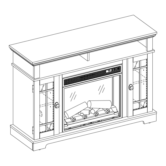
CANTERIDGE ELECTRIC FIREPLACE MEDIA MANTEL
QUESTIONS, PROBLEMS, MISSING PARTS? BEFORE RETURNING TO THE STORE,
CALL HOME DECORATORS COLLECTION CUSTOMER SERVICE
MONDAY - FRIDAY 8 A.M. - 7 P.M. EST, AND SATURDAY 9 A.M. - 6 P.M. EST.
1-800-986-3460
HOMEDEPOT.COM/HOMEDECORATORS
THANK YOU
We appreciate the trust and confidence you have placed in Home Decorators through the purchase of this electric fireplace. We strive to
continually create quality products designed to enhance your home. Visit us online to see our full line of products available for your home
improvement needs. Thank you for choosing Home Decorators!
Advertisement
Table of Contents

Related Manuals for Home Decorators Collection CANTERIDGE 1006152679/316091919/23MM90587-TPB01


Summary of Contents for Home Decorators Collection CANTERIDGE 1006152679/316091919/23MM90587-TPB01
- Page 1 USE AND CARE GUIDE CANTERIDGE ELECTRIC FIREPLACE MEDIA MANTEL QUESTIONS, PROBLEMS, MISSING PARTS? BEFORE RETURNING TO THE STORE, CALL HOME DECORATORS COLLECTION CUSTOMER SERVICE MONDAY - FRIDAY 8 A.M. - 7 P.M. EST, AND SATURDAY 9 A.M. - 6 P.M. EST. 1-800-986-3460 HOMEDEPOT.COM/HOMEDECORATORS...
-
Page 2: Table Of Contents
Table of Contents Maximum Load Warning ........... 2 Package Contents .............. 7 Safety Information ............. 3 Assembly ..............8 Warranty ..............5 Operation ..............17 Pre-Assembly ............. 6 FCC/IC Information ............20 Hardware Included ........... 6 Care & Cleaning ............20 Product Specifications ............ -
Page 3: Safety Information
Safety Information Please read and understand this entire manual before attempting to assemble, operate or install the product. If you have any question regarding the product, please call customer service at 1-800-986-3460, Monday-Friday 8 A.M. - 7 P.M. EST, WARNING: Under no circumstances should this fireplace be and Saturday 9 A.M. - Page 4 Safety Information (continued) NOTE: Use care in assembling your new fireplace. Take your time and use the hardware provided and a quality Phillips head screwdriver. Never overtighten bolts. • Do not sit on any part of the mantel. NOTE: To avoid injury from unexpected starting or electrical shock, do not plug the power cord into a source of power during unpacking and assembly.
-
Page 5: Warranty
Warranty Warranty 1 Year Limited Warranty: The manufacturer warrants that your new Electric Fireplace is free from manufacturing and material defects for a period of one year from date of purchase, subject to the following conditions and limitations. Install and operate this appliance in accordance with the installation and operating instructions furnished with the product at all times. -
Page 6: Pre-Assembly
Pre-Assembly HARDWARE INCLUDED Part Description Part Number Quantity Screw 4 x 50 mm PH-SCRBLK006 Screw 3 x 12 mm PH-SCRBLK007 Magnetic Catch PH-MCHBRW001 Screw 3 x 15 mm PH-SCRBLK010 Screw 3.5 x 19 mm P23MM90587-EE Back Panel Bracket PH-BKTBLK017 Handle with Screw K576 Shelf Pin PH-SPNPCSPLB2... -
Page 7: Package Contents
Pre-Assembly (continued) PACKAGE CONTENTS NOTE: All panels are labeled left and right as viewed from the front of unit. Part Description Quantity Base Left Partition Top Surround Rail Right Partition Left Side Panel Right Side Panel Top Panel Back Panels Left Media Shelf Partition Center Media Shelf Partition Right Media Shelf Partition... -
Page 8: Assembly
Assembly Attaching the center fireplace surround Locate the Top Surround Rail (C) as well as the Left and Right Partitions (B and D). Align the Top Surround Rail (C) between the Left and Right Partitions (B and D). Push together, inserting the pre-installed dowels on the Top Surround Rail (C) into the holes on the Left and Right Partitions (B and D) as shown. - Page 9 Assembly (continued) Attaching the side panel Align the Left and Right Side Panels (E and F) with the Bottom Shelf (A). Insert Screws (AA) through the Bottom Shelf (A) and into the pre-drilled holes on the edges of the Left and Right Side Panels (E and F) as shown.
- Page 10 Assembly (continued) Attaching door handles Locate the Cabinet Doors (N and O). Each Door Handle (GG) has pre-attached screws. Remove these screws and place handles over the pre-drilled holes in each Cabinet Door (N and O). Place the pre-attached screws on the other side of the Cabinet Doors (N and O) and tighten with a Phillips screwdriver through the door and into the handle.
- Page 11 Assembly (continued) Assembling the top panel Locate the Top Panel (G) and the Left, Center, and Right Media Shelf Partitions (I, J, K). Align the Left Media Shelf Partition (I) with the screw holes beneath the Top Panel (G). After inserting the screw on the Left Media Shelf Partition (I) into the hole, tighten the fastener using a Phillips Screwdriver as shown.
- Page 12 Assembly (continued) Attaching the door catches Locate the Center Shelf (M) and place on a flat surface. Attach the Magnetic Door Catches (CC) to the Center Shelf (M) using Screws (DD) where indicated by the diagram. Attaching the center shelf Align the Center Shelf (M) with the top assembly.
- Page 13 Assembly (continued) Attaching the top Align the main assembly with the screw holes beneath the Center Shelf (M). After inserting the screws into the holes, tighten the fasteners using a Phillips Screwdriver as shown. Securely fasten each screw on the main assembly to the Center Shelf (M).
- Page 14 Assembly (continued) Securing the back panels Place the Back Panel Brackets (FF) between the back panels and the grooves of the assembly as shown. Fasten each Back Panel Bracket (FF) using Screws (EE). Repeat until all brackets are in place as indicated by the diagram.
- Page 15 Assembly (continued) Attaching the cabinet doors Lift the Fireplace Insert (Q) carefully into the back of the unit and center in the fireplace insert opening. Do not drag the Fireplace Insert (Q) across the base as it may scratch your unit. Securing the fireplace insert Align the Metal Brackets (II) behind the fireplace insert and above the pre-drilled holes.
- Page 16 Assembly (continued) Installing the tipping restraint hardware When the Tipping Restraint Hardware (KK) is properly installed, it can provide protection against unexpected tipping of the Unit due to small tremors, bumps or Wall climbing. Each Tipping Restraint Hardware (KK) includes one Unit Anchor, one Wall Anchor, one Anchor Tether, and four Anchor Screws.
-
Page 17: Operation
Operation Operation NOTE: The control panel can be accessed at the upper-right corner of the insert. Powering the fireplace Adjusting the flame Push the Power button to supply power to all There are 6 brightness levels that can be selected: functions of the fireplace and put the insert in a standby mode. - Page 18 Operation (continued) Replacing the remote control battery Disposing of used batteries The battery may contain hazardous substances that When the remote control stops operating or its range could endanger the environment and human health. seems reduced, it is time to replace the battery with new ones.
- Page 19 Operation (continued) Patented Safer Plug® information SAFER PLUG This product is equipped with a Safer Plug®, which is an advanced safety device that helps detect electrical fires caused from faulty outlets. Overloading of outlets, adapters and surge protectors may cause overheating, damage, and increased risk of fires.
-
Page 20: Fcc/Ic Information
FCC/IC Information WARNING: Changes or modifications to this unit not expressly approved by the party responsible for compliance could void user’s authority to operate the equipment. NOTE: This equipment has been tested and found to comply with the limits for Class B digital device, pursuant to part 15 of the FCC Rules. -
Page 21: Troubleshooting
Troubleshooting PROBLEM ROOT CAUSE CORRECTIVE ACTION Fireplace has reached set temperature. Fireplace stopped heating before Set the fireplace to a higher temperature or Temperature around fireplace might be a few reached desired temperature. always “on”. degrees higher than other area in the room. Unplug the fireplace, remove the back panel of the fireplace and check that the The thermostat sensor is... - Page 22 Troubleshooting (continued) PROBLEM ROOT CAUSE CORRECTIVE ACTION Flame effect works but heater With the power on press and hold the Power function does not and the emberbed button on the control panel for 10 seconds. The heater is disabled. flashes when the Heater button is Once re-enabled the emberbed lights will pressed.
-
Page 23: Replacement Parts
Replacement Parts For replacement parts, call our customer service department at 1-800-986-3460, Monday - Friday 8 A.M. - 7 P.M. EST, and Saturday 9 A.M. - 6 P.M. EST. Part Description Qty. Remote Control Flame Circuit Board Blue LED Circuit Board Flame Generator Drive Motor Thermostat Sensor Blower/ Heater Assembly... - Page 24 HOMEDEPOT.COM/HOMEDECORATORS Please contact 1-800-986-3460 for further assistance.
- Page 25 Questions, problems, missing parts? Before returning to the store call Home Decorators Customer Service Monday - Friday 8 A.M. - 7 P.M. EST, and Saturday 9 A.M. - 6 P.M. EST. 1-800-986-3460 HOMEDEPOT.COM/HOMEDECORATORS RETAIN THIS MANUAL FOR FUTURE USE.
Need help?
Do you have a question about the CANTERIDGE 1006152679/316091919/23MM90587-TPB01 and is the answer not in the manual?
Questions and answers