Table of Contents
Advertisement
Quick Links
HazardControl
HC520
Assembly and Operating Instructions
en
Escape route control unit for the second
emergency route
Important information for:
• Fitters / • Electricians / • Users
Please forward accordingly!
These instructions must be kept safe for future reference.
4007 630 030 0f 04/11/2022
Becker-Antriebe GmbH
Friedrich-Ebert-Straße 2-4
35764 Sinn/Germany
www.becker-antriebe.com
Advertisement
Table of Contents

Related Manuals for Becker HazardControl HC520


Summary of Contents for Becker HazardControl HC520
- Page 1 Escape route control unit for the second emergency route Important information for: • Fitters / • Electricians / • Users Please forward accordingly! These instructions must be kept safe for future reference. 4007 630 030 0f 04/11/2022 Becker-Antriebe GmbH Friedrich-Ebert-Straße 2-4 35764 Sinn/Germany www.becker-antriebe.com...
-
Page 2: Table Of Contents
Table of contents General .................... 3 Warranty .................... 3 Safety instructions ................... 4 Intended use ................... 5 Device overview .................. 6 Wiring ..................... 6 Explanation of functions ................ 9 Setting and function of the DIP switches ........... 10 Setting the limit positions without connecting to the control unit.... 11 Maintenance .................. 12 Disposal .................... 12 Technical data .................. 13... -
Page 3: General
General The control unit, delivered ex works, controls a DC tubular drive automatically or via external drive commands. The control unit offers the opportunity of automatically raising the shading solution in the event of power failure, due to a fire, for example. Explanation of pictograms CAUTION indicates a hazardous situation CAUTION... -
Page 4: Safety Instructions
Safety instructions The following safety instructions and warnings are intended to avert hazards and to prevent property damage and personal injury. General information • Always comply with the regulations of local energy supply companies as well as the VDE 100 provisions for wet and damp rooms during installa- tion. -
Page 5: Intended Use
The escape route control unit for the second emergency route described in these instructions is intended for the supply and operation of an M19 model DC tubular drive from Becker-Antriebe, which can be activated even in the event of power failure. -
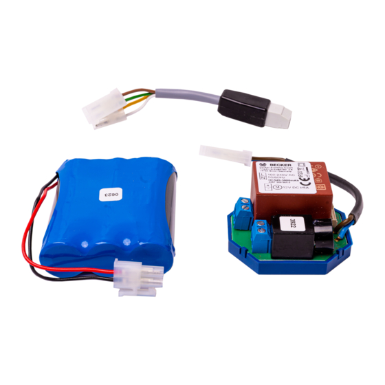
Page 6: Device Overview
Device overview Connection for individual and Connection for the safety central operation switch and drive Connection for the battery Mains connection and the safety switch Wiring Caution • Risk of injury due to electric shock. • Connection may only be performed by a qualified electri- cian! •... - Page 7 Connect the device as follows: Drive Individual operation 12 V DC (push-button) Mains 100–240 V AC 50/60 Hz Connection: Control grey black purple orange Optional blue HC520 Connection: Battery Safety switch Battery P6-20, P10-11 R20-17 a + b ≤ 10 m a + b ≤ 5 m a + c ≤...
- Page 8 If the shading solution rotates in the incorrect direction, the safety switch con- nections will need to be swapped around as follows: • Connections "A" and "B" with incorrect implementation of the function selected with DIP switch 5 in the event of power failure. •...
-
Page 9: Explanation Of Functions
Explanation of functions Automatic opening movement in the event of power failure In the event of power failure, the drive automatically raises the shading solu- tion with a battery buffer (can be set using DIP switches). This function is switched on upon delivery. Safety switch If the control unit is no longer functional due to a fire, the escape route can still be opened in spite of this. -
Page 10: Setting And Function Of The Dip Switches
Setting and function of the DIP switches Factory setting: All the DIP switches are set to OFF. Switch Position Function Individual operation preferred over central input DIP 1 Central input preferred over individual operation No alarm message (signal tone) DIP 2 Alarm message (signal tone) after 1,000 travel cycles or two years DIP 3... -
Page 11: Setting The Limit Positions Without Connecting To The Control Unit
Switch Position Function No blockage detection DIP 6 Blockage detection in the DOWN direction with re- versal Setting the limit positions without connecting to the control unit If the limit positions are to be set before the controller is installed, proceed as follows: Connect the tubular drive to the Y plug. -
Page 12: Maintenance
Maintenance We advise replacing the battery and having the system maintained by a spe- cialist company according to the information contained in the handover report at regular intervals, at the latest every 1,000 travel cycles or every two years. On delivery, the escape route control unit is set using the DIP switch 2 so that an alarm message (signal tone) sounds when the battery has to be replaced. -
Page 13: Technical Data
Technical data Type HC520-2600 mAh HC520-3000 mAh Rated voltage 100-240 V AC 50/60 Hz Switching current 5 A / 12 V DC 6.3 A / 12 V DC Power consumption 1.1 VA Degree of protection IP 20 Class of protection (dependent on correct assembly) Permissible ambient temperature 0 to +60 °C Type of mounting Flush mounted... -
Page 14: What To Do If
What to do if...? Problem Remedy Drive is not functioning. Check connection. Check position of safety switch. Drive is running in the wrong direc- Replace stranded wires for tion. The control unit does not carry out Check DIP switch setting. the automatic opening movement. -
Page 15: Simplified Eu Declaration Of Conformity
Simplified EU declaration of conformity Becker-Antriebe GmbH hereby declares that this control unit complies with Directives 2014/30/EU and 2014/35/EU. The full text of the EU declaration of conformity is available at the following web address: www.becker-antriebe.com/ce Subject to technical changes without notice. -
Page 16: Handover Report For The Customer
Handover report for the customer The installing company hereby confirms that the following work and functions have been carried out and checked. • Connection of the escape route control unit according to these instruc- tions. • Two-pole changeover switch installed as a safety switch. •... - Page 17 17 - en...
-
Page 18: Handover Report For The Installing Company
Handover report for the installing company The installing company hereby confirms that the following work and functions have been carried out and checked. • Connection of the escape route control unit according to these instruc- tions. • Two-pole changeover switch installed as a safety switch. •...
Need help?
Do you have a question about the HazardControl HC520 and is the answer not in the manual?
Questions and answers