GFA TS 971 Installation Instructions Manual
Door control
Hide thumbs
Also See for TS 971:
- Installation instructions manual (68 pages) ,
- Operating instructions manual (64 pages) ,
- Manual (49 pages)

Related Manuals for GFA TS 971


Summary of Contents for GFA TS 971
- Page 1 Installation Instructions Door control - TS 971 -en- 51000971.00002 Status: a / 05.2023 0000000 0000 51000971 00002...
- Page 2 The GfA-Stick is available for setting and servicing works on the door. Together with the GfA+ App, the tool enables reading and display of important data from GfA door controls TS 959, TS 970 and TS 971 via smartphone or tablet PC. This data includes, for example: ...
-
Page 3: Table Of Contents
Storage ............................... 6 Transport ............................6 Product overview ..........................7 Technical data ..............................7 Overview display TS 971 ..........................8 Status displays of the door control ......................... 9 Mechanical installation ........................10 Electrical installation ......................... 11 Overview connection cable XES ........................11 Overview connection cable DES/NES ...................... - Page 4 P 9.3 - Readout of the cycle counter since last programming change ............41 P 9.4 - Readout software version ......................... 41 P 9.5 - Reset to factory settings / use of GfA-Stick ..................42 P 9.6 - Reading out WSD door-module data ....................42 10 Fault correction ..........................
-
Page 5: Safety-Relevant Chapter
Note: Points out useful additional information. Intended use The door control is intended for installation in a force-actuated door with GfA limit switch system. The drive unit must be protected against moisture and aggressive environmental conditions (such as corrosive substances). The drive units are only suitable for indoor use. Appropriate protective measures must be taken for outdoor installation. -
Page 6: Safe Operation
Observe all specifications, especially warnings, when installing the product in the overall system. GfA is not liable for damage resulting from non-observance of the installation instructions. The resulting overall system must be reassessed for its safety in accordance with applicable standards and directives (e.g. CE marking). -
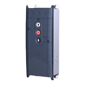
Page 7: Product Overview
230 V AC, 1 A 24 V DC, 0,4 A inductive Control inputs 24 V DC, typ. 10 mA Compatible GfA - limit switch Mechanical limit switch (NES) Digital limit switch (DES) Integrated radio receiver WSD-door module 2,4 GHz... -
Page 8: Overview Display Ts 971
Overview display TS 971 DES/ xxxxx F1 = 1,6A t DES/ DES or NES limit switch socket 24 V mains supply, external devices Mains supply Micro-fuse 1.6 A time-lag Door safety switch and safety devices Motor socket Selector switch Emergency STOP control device... -
Page 9: Status Displays Of The Door Control
Status displays of the door control The display of the door control consists of a double- digit seven-segment-display. The display can show symbols, letters, or numbers. The figure shows the display when all segments are illuminated. i NOTE An E alternating with a number on the door control stands for a movement command. An F alternating with a number on the door control stands for a fault indication. -
Page 10: Mechanical Installation
Movement command display The movement commands appear on the display when the door control receives OPEN, CLOSE or STOP commands. Display Description Display alternates between E. and number: OPEN command received. STOP command received. CLOSE command received. 5 Mechanical installation NOTICE Damage to components due to extreme environmental conditions! Extreme environmental conditions (humidity, chemical substances) at the installation site may damage the... -
Page 11: Electrical Installation
6 Electrical installation WARNING Danger to life from electric shock! Improper wiring may result in severe or fatal injury from electrical current. Allow only qualified electricians to carry out the work. Disconnect all cables from the power supply. ... -
Page 12: Overview Connection Cable Des/Nes
Overview connection cable DES/NES : DES/NES : MOT : X13 : X12 : X12 Ⓐ ↔ Ⓑ Ⓒ ↔ Ⓓ Core Pin Description Core Description ① ① ① 5/ws Safety circuit +24 V Phase W ② ② ② 6/br Channel B (RS485) Phase V ③... -
Page 13: Connecting Door Control And Drive Unit
Connecting door control and drive unit NOTICE Damage to the product due to work carried out improperly Use proper tools to prevent damage and leakage. We recommend wiring the door control from below. 1. Remove the covers. 2. Open the cable entries at the top or bottom. 3 a) Connection cable at the top: 3 b) Connection line at the bottom: ... -
Page 14: Mains Supply
Mains supply Before connecting, check whether a clockwise rotating field is present at the installation site. If not, create a clockwise rotating field. 3-phase with neutral 3-phase without neutral 1-phase symmetrical 1-phase asymmetrical 3~, N, PE 3~, PE 1~, N, PE, sym. 1~, N, PE, asymmetrical 220–400 V / 50-60 Hz 220–400 V / 50-60 Hz... -
Page 15: Connecting External Devices
7 Connecting external devices WARNING Danger to life from electric shock! Improper wiring may result in severe or fatal injury from electrical current. Allow only qualified electricians to carry out the work. Disconnect all cables from the power supply. ... -
Page 16: X1 - Mains Supply / Supply Of External Devices
X1 - Mains supply / supply of external devices Mains supply of the door control. Note the chapter "Electrical installation / mains supply". i NOTE Supply of external devices External devices can only be supplied with power over terminals X1/1.8 and X1/1.9 when the door control is connected symmetrically to supply networks with 3 N~ 400 V or 1 N~ 230 V. - Page 17 Optical safety edge The input is intended for an infrared safety photocell with a transmitter and receiver in a rubber profile. Pressing the rubber profile interrupts the light beam. Connection socket Voltage supply (12 V) Input for door safety switch SK/b Mains supply (brown) SK/b...
-
Page 18: X2 - Door Safety Switch
X2 - Door safety switch You can connect a door safety switch for a pass door or slack-rope switch to terminals X2.1/2.2. The door safety switches are connected to a safety circuit with Performance Level c (PLc) according to ISO 13849-1. The safety circuit requires an overall terminal resistance of 5k0 for line cross-circuit monitoring. -
Page 19: X3 - Emergency Stop
Crash switch as NO contact Connection socket Voltage supply (12 V) Input for door safety switch Crash switch (NO contact) X3 - Emergency Stop The emergency STOP control device is connected to a safety circuit with Performance Level c (Plc) according to ISO 13849-1. Alternativly you can connect an emergency STOP control device as per EN 13850 or an evaluation unit for an anti-trap safety device. -
Page 20: X5 - External Control Device
X5 - External control device You can connect an external control device for operating the door to terminals X5.1 to X5.4.The control device loses its function when faults occur on the safety edge, light curtain or photocell. Install the product according to the manufacturer‘s instructions. Several examples of control devices are shown. - Page 21 Photocells A photocell is used for object protection and activated with operating modes 0.3 / 0.4. The photocell only switches in the final limit position OPEN and during CLOSE operation. 1 2 3 4 5 1 2 3 4 5 A8: Reflective photocell Through photocell Through photocell...
-
Page 22: X7 - Radio Receiver / Pull Switch
X7 - Radio receiver / pull switch You can connect a pull switch or radio receiver to terminals X7.1/X7.2. The switching contact must be potential-free. Install the product according to the manufacturer‘s instructions. 1 2 3 4 Activate the product after completion of the electrical installation with menu item 2.6. -
Page 23: X20 / X21 - Relay Contacts For Traffic Lights, Light Curtains Or Magnetic Brakes
X20 / X21 - Relay contacts for traffic lights, light curtains or magnetic brakes You can connect more external devices, such as traffic lights, to terminals X20.1-X20.3 and X21.1-X21.3. X20 and X21 are potential-free relay contacts. Install the product according to the manufacturer‘s instructions. ... -
Page 24: Setting The Final Limit Positions
8 Setting the final limit positions The following explains how to set the final limit positions of the door at the initial commissioning. i NOTE You can correct the final limit positions later with menu items P 1. 1 - P 1.4. Setting the final limit positions - DES (digital limit switch) If you have already connected a safety edge, the pre-limit is automatically set with the final limit positions. -
Page 25: Programming
9 Programming i NOTE Before you can start programming, you must have set the final limit positions. Programming the door control 1. Start programming: Press the selector switch for 3 seconds. The display changes to 0.0. 2. Select the menu item: ... -
Page 26: Menu Items
Menu items: P 0.1 - Operating mode With this menu item, you select the operating mode for moving the door during OPEN operation and CLOSE operation. When selecting the option, note the following: ▪ the number of safety devices and safety edges at the door. ▪... -
Page 27: P 0.3 - Selection Of The Safety Devices
P 0.3 - Selection of the safety devices i NOTE This menu item is only enabled at initial operation or after a complete reset. The selection must be made before setting the final limit positions. The selection is retained even after a reset but can then be changed. Selection of the safety devices Spiral cable or WSD ►... -
Page 28: P 1.6 - Door Positions For Intermediate Open
P 1.6 - Door positions for intermediate open Use this menu item to set the door position for intermediate open. Intermediate open is a door position between final limit positions OPEN and CLOSE. This requires the connection of an external switch to the two terminals of connector X8. -
Page 29: P 1.7 / 1.8 - Switching Position Of Relays X20/X21
P 1.7 / 1.8 - Switching position of relays X20/X21 With this menu item you can set the door position in which relays X20 and X21 switch. To use this function, you must set menu item P 2.7/P 2.8 and connect a device to X20 and/or X21. You only have to teach-in this switching position if you want to use the options .1 / .2 or 1. -
Page 30: P 2.0 - Safety Device
P 2.0 - Safety device With this function, you assign a radio channel to the WSD door module (Wireless Safety Device). If you are using a spiral cable, leave the menu item in option .0. Also refer to Chapter X2: Safety devices. Safety device Spiral cable ►... -
Page 31: P 2.1 - Safety Edge In Pre-Limit Area
P 2.1 - Safety edge in pre-limit area Use this menu item to activate or deactivate the safety edge in the pre-limit area. Function of the safety edge system in the pre-limit area Safety edge active ► Safety edge is inactive (e.g. with a non-contact photocell) Ground adjustment (DES) Reversing in overrun area (DES) Ground adjustment... -
Page 32: P 2.3 - Automatic Closing
P 2.3 - Automatic closing With this menu item, you can select a time between 1 and 240 seconds after which the door closes automatically. You can connect a switch for activating and deactivating this function to terminals X4.1 and X4.2. -
Page 33: P 2.5 - Limiting Reversals
P 2.5 - Limiting reversals Activate this menu item only if automatic closing 2.3 is enabled. When automatic closing is enabled, the door moves to final limit position CLOSED after the set time. The door reverses when hitting an obstacle during movement. -
Page 34: P 2.7/2.8 - Relay Functions On X20/ X21
P 2.7/2.8 - Relay functions on X20/ X21 With menu item P 2.7, you control the function of X20 and with P 2.8 the function of X21. Both menu items have the same options. Terminals X20/X21 are potential-free relay contacts. Relay function on X20 Relay function on X21 Off. -
Page 35: P 2.9 - Specifying Control Device For Intermediate Open
P 2.9 - Specifying control device for intermediate open Use this menu item to specify the control devices for approaching intermediate open. You must first set a position for intermediate open with menu item 1.6. To switch intermediate open off and on, a switch must be installed on X8. -
Page 36: P 3.2 - Interruption Of The Photocell
P 3.2 - Interruption of the photocell The function is only available für door drive units with digital limit switch (DES). Components on the door (e.g. spiral cables) may interrupt the photocell always in the same position. A fault indication appears. Use this menu item for setting the position. During CLOSE operation, the photocell will be deactivated from this position onwards. -
Page 37: P 3.4 - Door Safety Switch
P 3.4 - Door safety switch The door safety switch is connected to input X2.2. Door safety switch Slack-rope switch / Pass-door switch ► Crash switch as NC contact After activation: "Hold-to-run" door operating mode Crash switch as NO contact After activation: "Hold-to-run"... -
Page 38: P 4.1 - 4.9 - Frequency Inverter Functions
P 4.1 – 4.9 - Frequency inverter functions The following menu items are only visible and applicable if the door drive unit is equipped with a mounted frequency inverter. Increasing / decreasing the output speed Use this menu item to change the output speed of the door drive unit equipped with a frequency inverter. With menu item you can additionally increase the closing output speed from a height of 2.5 m onwards. -
Page 39: P 7.6 - Selection Of Radio Transmitter System
Selection of radio transmitter system Internal radio receiver deactivated ► (Fixcode) GfA, Tedsen Teleco „COD1“ GfA UK, JCM, Dickert, RDA (Rolling code of various providers) .5 - 1.0 i NOTE A combination of different radio transmitter manufacturers is possible. -
Page 40: P 8.5 - Setting The Maintenance Cycle Counter
P 8.5 - Setting the maintenance cycle counter With these menu items, you set a reminder for the maintenance of the door. The maintenance cycle can be set between 1,000 and 99,000 cycles. The counter decreases by 1 every time the door reaches the final limit position OPEN. -
Page 41: P 9.2 - Readout Of Fault Indications
Number of activations of slack-rope, pass-door and crash switch P 9.4 - Readout software version This menu item displays the software version of the door control. For drive units with GfA frequency inverter, the software version of the motor is shown as well. -
Page 42: P 9.5 - Reset To Factory Settings / Use Of Gfa-Stick
Activate the GfA-Stick with option .0 The GfA-Stick (part no. 20003696) allows readout of faults, operations, and programming by using the GfA App. With option . 1, you delete all set menu items and reset the door control to factory setting. -
Page 43: Fault Correction
NOTE You can find detailed information on faults and how to rectify them in our fault guide for door controls. Download the fault guide from the GfA-Portal. Start the fault guide using the GfA+ app. Emergency operation WARNING Danger from uncontrolled movements or falling parts! In emergency operations, all safety devices are bypassed. -
Page 44: Fault Indications
Fault indications Door control is off / display is dark Possible causes Fault correction No input function Measure the input voltage. Check whether too many electrical loads are connected to the Overload control circuit (24 V). Display is dark / door Check whether a faulty device is connected to the control control is... - Page 45 The radio transmission of WSD door- Obstacle between WSD door-module and door control: module is not working. (TS 971) Adapt the fitting configuration or use a spiral cable. Battery voltage is too low: Read out the voltage using menu item 9.6 and replace the battery if it is less than 3.2 V...
- Page 46 Check the condition and alignment of the photocell. Remove obstacles from door area. Photocell activated. 2. 1 Clean the photocell and the reflector. Check the connection cable for breaks. Replace photocell if necessary. Remove obstacles from door area. Maximum reversing number Check the door mechanism for damage.
- Page 47 Fault at limit switch Cause of the fault Fault correction Display alternates between F and number Check if the emergency manual operation is activated. The contact of the emergency Measure the contact of the emergency manual operation manual operation is open or faulty. electrically.
- Page 48 Internal faults of the door control / force monitoring Cause of the fault Fault correction Display alternates between F and number Measure the input voltage. Check the fuses of the supply line. Internal plausibility error. Establish a stable power supply. The mains supply of the door Measure the voltage under load.
- Page 49 Fault of door movement Cause of the fault Fault correction Display alternates between F and number Check the limit switch plug for firm seating. Check the connection cable visually for damage. Fault of digital limit switch (DES). Check the limit switch by replacing it with a properly functioning DES.
- Page 50 Fault on the frequency converter These fault indications appear only for door drive units with a frequency inverter. Cause of the fault Fault correction Display alternates between F and number Check the door mechanism for stiffness. Only for doors with counter-balancing: check for spring The closing speed is too high.
-
Page 51: Maintenance
Dispose of old devices properly according to local legal regulations. Return old devices to the return and collection systems available. You can also return GfA products free of charge. Please apply enough postage to the package and mark it as "old devices". -
Page 52: Ukca Declaration Of Conformity
Electronic Equipment Regulations 2021 within the meaning of Radio Equipment Regulations 2017 The following requirements from Appendix I of the GfA ELEKTROMATEN GmbH & Co. KG Supply Machinery (Safety) Regulations 2008 are met: declare under our sole responsibility that the 1.1.2, 1.1.3, 1.1.5, 1.2.2, 1.2.3, 1.2.6, 1.3.2, 1.3.3,... -
Page 53: Declaration Of Incorporation / Declaration Of Conformity
RoHS Directive 2011/65/EU within the meaning of RED Directive 2014/53/EU The following requirements from Appendix I of the GfA ELEKTROMATEN GmbH & Co. KG Machinery Directive 2006/42/EC are met: declare under our sole responsibility that the 1.1.2, 1.1.3, 1.1.5, 1.2.1, 1.2.2, 1.2.3, 1.2.4.2, 1.2.5,...
Need help?
Do you have a question about the TS 971 and is the answer not in the manual?
Questions and answers