Sign In
Upload
Manuals
Brands
GFA Manuals
Control Unit
TS 971
GFA TS 971 Manuals
Manuals and User Guides for GFA TS 971. We have
5
GFA TS 971 manuals available for free PDF download: Installation Instructions Manual, Operating Instructions Manual, Manual
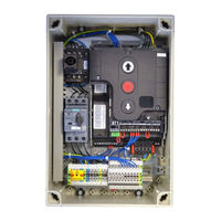
GFA TS 971 Installation Instructions Manual (68 pages)
Door control. Automatic control panel with radio.
Brand:
GFA
| Category:
Controller
| Size: 3 MB
Table of Contents
Table of Contents
3
1 General Safety Information
6
2 Technical Data
7
3 Mechanical Installation
8
4 Electrical Installation
9
Connection Cable Connection Overview
10
Limit Switch Configuration, Screwable Version up to Year of Construction in 1997
11
Limit Switch Configuration, Single Limit Switches
11
Carrying out the Electrical Installation
12
Mains Supply
13
Mains Supply to Control
13
Completing the Electrical Installation
13
Overview of Control
14
5 Starting up the Control
15
DES: Rapid Adjustment of Final Limit Positions
15
NES: Rapid Adjustment of Final Limit Positions
16
6 Advanced Electrical Installation
17
Connection of Spiral Cable / Light Curtain X2
17
Door Safety Switch / Crash Switch X2
18
External Supply X1
18
Emergency Stop X3
18
Automatic Closing, On/Off X4
18
External Control Device X5
19
Photo Cell X6
19
Light Curtain X6
19
Radio Receiver X7
20
Pull Switch X7
20
Intermediate Open X8
20
Red/Green Traffic Lights X20 / X21
20
Magnetic Brake X20 / X21
20
WSD Door-Module (Wireless Safety Device)
21
Electrical Safety Edge 8K2 to WSD Door-Module
21
Optical Safety Edge OSE System 1 to WSD Door-Module
21
Optical Safety Edge OSE System 2 to WSD Door-Module
22
Door Safety Switch on "WSD" Door Module
22
Teach-In of WSD Door-Module
23
Completing the Advanced Electrical Installation
23
7 Control Programming
24
8 Table Menu Items
25
Door Operating Modes
25
Door Positions
26
Door Functions
27
Safety Functions
31
DI/FI Settings
32
Extended Door Functions
33
Maintenance Cycle Counter
34
Readout of Data Memory
35
Deleting / Readout
35
Reading out WSD Door-Module Data
36
9 Safety Devices
37
X2: Input, Door Safety Switch Function
37
X2: Input for Safety Devices
39
Installation of the Spiral Cable
40
Integrated WSD Door-Module
43
EMERGENCY Operation
45
X3: Input, Emergency Stop
45
10 Functional Description
46
X: 24 VDC Voltage Supply
46
X1: Mains Supply of the Control and Supply of External Devices
46
X4: Input, Automatic Closing Off/On
47
X5: Input, Control Device
47
X6: Input "Through / Reflective Photo Cell" Resp. Light Curtain
48
X7: Input Pull Switch/Radio Receiver
51
Internal Radio Receiver
52
Teach-In of Radio Transmitter
52
Deleting an Individual Radio Transmitter
53
Deleting All Radio Transmitters
53
X8: Input, Intermediate Stop On/Off
54
X20 / X21: Potential-Free Relay Contacts
55
Force Monitoring (des Only)
55
Travel Time Monitoring (NES Only)
56
UBS System
57
UBS Connection
57
Reversing Duration Adjustment
57
Maintenance Cycle Counter
58
Short-Circuit/Overload Display
58
Display for Active WSD Door-Module Wireles Safety Device
58
Standby Function
58
Illumination of the Built in Push Button of the Door Control
58
11 Status Display
59
Faults
59
Commands
64
Status Indications
65
12 Explanation of Symbols
66
13 Declaration of Incorporation / Declaration of Conformity
68
Advertisement
GFA TS 971 Operating Instructions Manual (64 pages)
Brand:
GFA
| Category:
Control Unit
| Size: 2 MB
Table of Contents
Table of Contents
2
1 General Safety Information
5
2 Technical Data
6
3 Mechanical Installation
7
4 Electrical Installation
8
Connection Cable Connection Overview
9
Carrying out the Electrical Installation
10
Mains Connection
11
Mains Connection to Control
11
Completing the Electrical Installation
11
Overview of Control
12
5 Starting up the Control
13
DES: Rapid Adjustment of Limits
13
6 Electrical Installation - Control Accessories
14
X1 External Supply
14
X3 Emergency Stop
14
X4 Automatic Closing On/Off
14
X5 Control Device
14
X5 / X6 Radar Motion Detector
14
X5 / X6 Infrared Radar System
14
X6 Photo Cell
15
X6 Light Curtain
16
X7 Radio Receiver
16
X7 Pull Switch
16
X8 Intermediate Stop
16
X20 / X21 Red / Green Traffic Light
16
X20 / X21 Magnetic Brake
16
Connection of Spiral Cable
17
WSD" Wireless Safety Device
18
8K2 Electrical Safety Edge System on "WSD" Door Module
18
OSE Optical Safety Edge System 1 on "WSD" Door Module
18
OSE Optical Safety Edge System 2 on "WSD" Door Module
19
Door Safety Switch on "WSD" Door Module
19
Teaching in of "WSD" Door Module
20
Completing the Electrical Installation
20
7 Control Programming
21
8 Table of Menus
22
Operating Mode
22
Door Positions
23
Door Functions
24
Door Positions
25
Door Positions
26
Door Positions
27
Safety Functions
28
DU/FI Settings
29
Advanced Door Functions
30
Maintenance Cycle Counter
31
Reading out Memory
32
Delete All Settings
32
Reading out WSD Data
33
9 Safety Devices
34
X2: Input, Door Safety Switch
34
X2: Input, Safety Edge System
36
Installation of the Spiral Cable
37
Integrated "WSD" Wireless Safety Device
39
EMERGENCY Operation
41
X3: Input, Emergency Stop
41
10 Functional Description
42
X: 24 V DC Voltage Supply
42
X1: Mains Supply Line for Control and External Supply
42
X4: Input, Automatic Closing Off/On
43
X5: Input, Control Device
43
X6: Input, "Through / Reflective Photo Cell" or Light Curtain
44
X7: Input, Pull Switch/Radio Receiver
47
Internal Radio Receiver
48
Teach-In of Radio Transmitter
48
Deleting an Individual Radio Transmitter
49
Deleting All Radio Transmitters
49
X8: Input, Intermediate Stop On/Off
50
X20 / X21: Potential-Free Relay Contacts
51
Force Monitoring
51
UBS System
52
UBS Connection
52
Reversing Duration Adjustment
52
Maintenance Cycle Counter
53
Short-Circuit/Overload Display
53
Display for Active "WSD" Wireless Safety Device
53
Standby Function
54
Lighting of the Internal Control Device
54
11 Status Display
55
Faults
55
Commands
60
Status Indications
61
12 Explanation of Symbols
62
13 Declaration of Incorporation/Declaration of Conformity
64
GFA TS 971 Installation Instructions Manual (53 pages)
Door control
Brand:
GFA
| Category:
Control Unit
| Size: 2 MB
Table of Contents
Table of Contents
3
Safety-Relevant Chapter
5
Explanation of Symbols
5
Intended Use
5
Target Audience of These Installation Instructions
5
Safe Operation
6
General Safety Instructions
6
Storage
6
Transport
6
Product Overview
7
Technical Data
7
Overview Display TS 971
8
Status Displays of the Door Control
9
Mechanical Installation
10
Electrical Installation
11
Overview Connection Cable XES
11
Overview Connection Cable DES/NES
12
Connecting Door Control and Drive Unit
13
Mains Supply
14
Connecting External Devices
15
Internal Radio Receiver - Handheld Transmitter
15
Power Supply 24V DC
15
X1 - Mains Supply / Supply of External Devices
16
X2 - Safety Devices
16
X2 - Door Safety Switch
18
X3 - Emergency Stop
19
X4 - Switch for Automatic Closing
19
X5 - External Control Device
20
X6 - Photocell and Light Curtain
20
X7 - Radio Receiver / Pull Switch
22
X8 - Switch for Intermediate Open
22
X20 / X21 - Relay Contacts for Traffic Lights, Light Curtains or Magnetic Brakes
23
Setting the Final Limit Positions
24
Programming
25
Programming the Door Control
25
Explanation of the Programming Tables
25
Menu Items
26
P 0.1 - Operating Mode
26
P 0.2 - Output Rotating Direction
26
P 0.3 - Selection of the Safety Devices
27
P 1.1 / 1.2 - Coarse Correction of Final Limit Position
27
P 1.3 - 1.5 - Fine Correction of Final Limit Positions
27
P 1.6 - Door Positions for Intermediate Open
28
P 1.7 / 1.8 - Switching Position of Relays X20/X21
29
P 2.0 - Safety Device
30
P 2.1 - Safety Edge in Pre-Limit Area
31
P 2.2 - Overrun Correction
31
P 2.3 - Automatic Closing
32
P 2.4 - Reaction of Automatic Closing to Photocell / Light Curtain
32
P 2.5 - Limiting Reversals
33
P 2.6 - Radio and Pull Switch Functions
33
P 2.7/2.8 - Relay Functions on X20/ X21
34
P 2.9 - Specifying Control Device for Intermediate Open
35
P 3.1 - Force Monitoring of Sectional Doors
35
P 3.2 - Interruption of the Photocell
36
P 3.3 - Travel Time Monitoring
36
P 3.4 - Door Safety Switch
37
P 3.5 - Automatic Opening
37
P 3.8 - Shorten/Lengthen the Reversing Time
37
P 4.1 - 4.9 - Frequency Inverter Functions
38
P 7.6 - Selection of Radio Transmitter System
39
P 7.7 - Radio Receiver Function
39
P 8.5 - Setting the Maintenance Cycle Counter
40
P 8.6 - Response after Expiry of the Maintenance Cycle Counter
40
P 9.1 - Readout of Cycle Counter
40
P 9.2 - Readout of Fault Indications
41
P 9.3 - Readout of the Cycle Counter Since Last Programming Change
41
P 9.4 - Readout Software Version
41
P 9.5 - Reset to Factory Settings / Use of Gfa-Stick
42
P 9.6 - Reading out WSD Door-Module Data
42
Fault Correction
43
Emergency Operation
43
Fault Indications
44
Maintenance
51
Disposal
51
UKCA Declaration of Conformity
52
Declaration of Incorporation / Declaration of Conformity
53
Advertisement
GFA TS 971 Installation Instructions Manual (45 pages)
Door control ATEX outside Ex-Zone Hold-To-Run-Mode
Brand:
GFA
| Category:
Gate Opener
| Size: 1 MB
Table of Contents
Table of Contents
3
Safety-Relevant Chapter
5
Explanation of Symbols
5
Target Audience of These Installation Instructions
5
Intended Use
5
Safe Operation
6
General Safety Instructions
6
Storage
6
Transport
6
Product Overview
7
Technical Data
7
Components
7
Overview Display TS 971
8
Status Displays of the Door Control
9
Mechanical Installation
11
Electrical Installation
12
Proof of Intrinsic Safety
12
Mains Supply
12
Motor Connection
13
Adjust Motor Protection Switch
14
Limit Switch Connection
15
Connecting External Devices
16
X2 - Door Safety Switch
17
External Command Devices: X2 Terminal Block
18
X3 - Emergency Stop Switch
19
X7 - Pull Switch
19
X8 - Switch for Intermediate Open
19
X20 / X21 - Relay Contact for the Brake / Relay Contact for the Relay Contact for a Traffic-Light
20
Setting the Final Limit Positions
20
NES (Mechanical Limit Switch)
20
Programming
21
Programming the Door Control
21
Explanation of the Programming Tables
21
Menu Items
22
P 0.1 - Operating Mode
22
P 0.2 - Output Rotating Direction
23
P 2.6 - Pull Switch
23
P 2.9 - Specifying Control Device for Intermediate Open
25
P 3.3 - Travel Time Monitoring
25
P 3.4 - Door Safety Switch
26
P 8.5 - Setting the Maintenance Cycle Counter
26
P 8.6 - Response after Expiry of the Maintenance Cycle Counter
26
P 9.1 - Readout of Cycle Counter
27
P 9.2 - Readout of Fault Indications
27
P 9.3 - Readout of the Cycle Counter Since Last Programming Change
28
P 9.4 - Readout Software Version
28
P 9.5 - Reset to Factory Settings / Use of Gfa-Stick
28
10 Fault Correction
29
Emergency Operation
29
Fault Indications
30
GFA TS 971 Manual (49 pages)
Brand:
GFA
| Category:
Control Unit
| Size: 1 MB
Table of Contents
Table of Contents
3
Connection of Drive Unit to Control Panel (Digital Limits)
4
Mains Supply - Three-Phase Door Drives
6
Mains Supply - Single-Phase Door Drives
7
Safety Brake - Connection to Drive Unit
8
Pairing of VR/K2E Wireless Keypad
10
Built-In Radio Receiver and Pairing Radio Transmitters
11
Connecting VR/XPL5 Multi-User Receiver
12
Loop Detector and Ground Loop(S)
13
Latching Emergency Stop Button
15
Access Control Devices
16
2No. PES/30T Photocells (Through-Beam)
20
1No. PES/30T Photocells (Through-Beam)
21
2No. PES/9R Photocells (Polarised Re Ective)
22
1No. PES/9R Photocells (Polarised Re Ective)
23
2No. PES/4.5TOF/POT (Time-Of-Flight Photocells)
24
1No. PES/4.5TOF/POT (Time-Of-Flight Photocell)
25
BS en 12453 - Minimum Levels of Safeguarding
26
KSR4P Wired Safety Edge Connections
27
KSR6 Wireless Safety Edge
30
GF304528 Raytector High Level Entrapment Protection Barrier
32
KGF/RAY-LG2520/OSE and KGF/RAY-LG2524/OSE Light Curtains
33
(2X) KGF/RAY-LG25XX/OSE Light Curtains
34
(1X) KGF/RAY-LG25XX/OSE Light Curtains and KSR 6 Wireless Safety Edge Box
35
230VAC Warning Light
36
GF301955 - Red and Green Tra C Indicator
37
JE419130 - Red and Green Tra C Indicator (24VDC Tra C Lights)
38
JE419130 - Red and Green Tra C Indicator (230VAC Tra C Lights)
39
1No. LZR Widescan with Auxiliary PSU
40
1No. LZR100 and 110 Laser Safety Sensor with Auxiliary PSU
41
2No. LZR100 and 110 Laser Safety Sensor with Auxiliary PSU
42
1No. Condor and Condor XL
44
1No. Falcon and Falcon XL
45
Power Supply for Control Accessories
46
Power Supplies Available
47
Interlocking 2No. TS 971 Control Panels
48
New Control with Previous Version KSR4P Optical Wired Safety Edge
49
Advertisement
Related Products
GFA TS 959
GFA TS 970
GFA TS 971 Series
GFA Elektromaten TS 956
GFA TS 981
GFA 30005154
GFA 30005854
GFA DC 8010
GFA DC 8010.0
GFA DC 8010.1
GFA Categories
DC Drives
Gate Opener
Industrial Equipment
Garage Door Opener
Controller
More GFA Manuals
Login
Sign In
OR
Sign in with Facebook
Sign in with Google
Upload manual
Upload from disk
Upload from URL