
Related Manuals for GFA DC 8010.0


Summary of Contents for GFA DC 8010.0
- Page 1 Installation Instructions Door control - DC 8010.0 / DC 8010.1 -en- 51018010.00002 Status: b / 04.2024...
-
Page 2: Table Of Contents
General safety instructions ..........................5 Storage ............................... 5 Transport ............................5 Product overview ..........................6 Technical DC 8010.0 ............................6 Technical data DC 8010.1 ..........................6 Overview Housing inside/outside ........................7 Overview display of the door control unit ......................8 Status displays of the door control .........................9 Mechanical installation ........................ - Page 3 P 9.3 - Readout of the cycle counter since last programming change ............41 P 9.4 - Readout software version ........................42 P 9.5 - Reset to factory settings / use of GfA-Stick..................42 10 Fault correction ..........................43 Fault indications ............................43 11 Disposal ............................
-
Page 4: Safety-Relevant Chapter
All work performed must be in accordance to NEC, local, state and federal codes. Intended use The door control is intended for installation in a force-actuated door with a GfA limit switch system. The drive unit must be protected against moisture and aggressive environmental conditions (such as corrosive substances). -
Page 5: Safe Operation
Observe all specifications, especially warnings, when installing the product in the overall system. GfA is not liable for damage resulting from non-observance of the installation instructions. These installation instructions refer only to a part of the overall system and are not sufficient as the sole instructions for the overall system. -
Page 6: Product Overview
4 Product overview Technical DC 8010.0 Designation Expression Dimensions (B x H x T) 500mm x 500mm x 210mm 19.7“ x 19.7“ x 8.3“ Weight 26 kg Operating frequency 60 Hz Supply voltage 220 V 460 V 575 V Output power for drive unit, maximum 4.5 kW... -
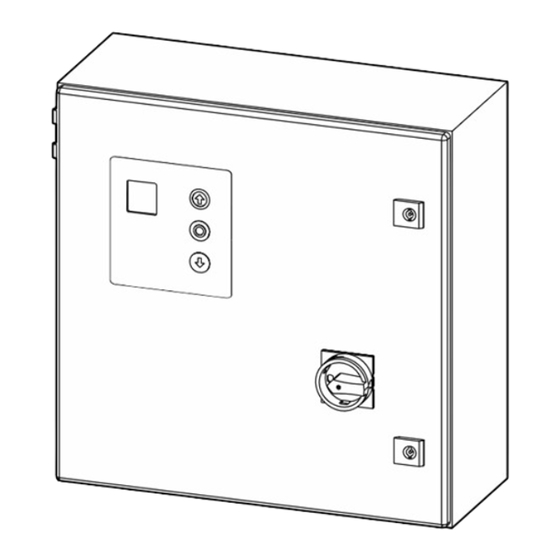
Page 7: Overview Housing Inside/Outside
Overview Housing inside/outside D.1 D.2 D.3 D.4 D.5 D.6 0 .1 0 .2 0 .3 0 .4 1 .1 0 1.1 1 1 .1 2 1 .1 3 2 .1 2 .2 2 .3 2 .4 2 .5 2 .6 2 .7 2 .8 3 .1 3 .2 4 .1 4 .2 5 .1 5 .2 5 .3 5 .4 2 4 V 6 .1 6 .2 7 .1 7 .2 8 .1 8 .2 2 0 . -
Page 8: Overview Display Of The Door Control Unit
Overview display of the door control unit D .1D .2 D .3D .4 D .5D .6 0.10.2 0.30.4 2 0 .12 0 .22 0 .3 2 1 .12 1 .22 1 .3 2.12.2 2.32.42.52.6 2.72.8 3.13.2 4.14.2 5.15.2 5.35.4 6.16.2 7.17.2 8.18.2 X4 X5 Connector bluetooth stick Power supply 24 V external devices... -
Page 9: Status Displays Of The Door Control
Status displays of the door control The display of the door control consists of a double- digit seven-segment-display. The display can show symbols, letters, or numbers. The figure shows the display when all segments are illuminated. i NOTE An E alternating with a number on the door control stands for a movement command. An F alternating with a number on the door control stands for a fault indication. -
Page 10: Mechanical Installation
Movement command display The movement commands appear on the display when the door control receives OPEN, CLOSE or STOP commands. Display Description Display alternates between E. and number: OPEN command received. STOP command received. CLOSE command received. 5 Mechanical installation NOTICE Damage to components due to extreme environmental conditions! Extreme environmental conditions (humidity, chemical substances) at the installation site may damage the... -
Page 11: Electrical Installation
6 Electrical installation WARNING Danger to life from electric shock! Improper wiring may result in severe or fatal injury from electrical current. ▪ Allow only qualified electricians to carry out the work. ▪ Disconnect all cables from the power supply. ▪... -
Page 12: Connecting Limit Switch To The Door Control
Connecting limit switch to the door control The following explains how to connect the digital limit switch (DES) of the door drive unit to the door control. For this you need a DES connecting cable. Attaching the DES connecting cable ▪... -
Page 13: Connecting Motor To Door Control
Connecting motor to door control A distinction is made between 3~ and 2~ door drive units. The required cable AWG depends on the door drive unit. Choose from the table on page 13. The length of the cable should not exceed 98,4 ft (30 m). i NOTE The motor protection against overheating of ELEKTROMATEN without FI complies with UL 1004-3 (thermal motor protector) according to UL 325:2020 Section 18 Overload Protection. -
Page 14: Motor Cable Conductor Size
Connecting the 2~ door drive unit You need a 3 conductor cable including ground. Select the cable AWG based on the table „Motorcable conductors size“. ▪ Remove the cover of the terminal box on the motor of the door drive unit. ▪... -
Page 15: Setting The Operating Voltage
Carry out the following steps only in a de-energized state. 220 V 460 V 575 V DC 8010 / DC 8010.0 / DC 8010.1 DC 8010 / DC 8010.0 DC 8010 / DC 8010.0 Connecting the door control to the power grid... -
Page 16: Main Switch
Main switch You can optionally connect a main switch to the DC 8010. DC 8010.0 mains supply to main switch Figure Ⓐ shows the connection for a switch to a ▪ 3~ mains. Figure Ⓑ shows the connection for a switch to a ▪... -
Page 17: Cable Plan
7 Cable plan Cable plan for door drives without FI... -
Page 18: Cable Plan - Door Drives With Frequency Inverter 3
Cable plan - door drives with frequency inverter 3~... -
Page 19: Cable Plan - Door Drives With Frequency Inverter 2
Cable plan - door drives with frequency inverter 2~... -
Page 20: Cable Plan - Door Drives With Frequency Inverter 2~ For Dc 8010.1
Cable plan - door drives with frequency inverter 2~ for DC 8010.1... -
Page 21: Connecting External Devices
8 Connecting external devices WARNING Danger to life from electric shock! Improper wiring may result in severe or fatal injury from electrical current. ▪ Allow only qualified electricians to carry out the work. ▪ Disconnect all cables from the power supply. ▪... -
Page 22: X2 - Safety Devices
X2 - Safety devices The door control detects three different types of fail safe safety edges: electrical, pneumatic, and optical ones. You can connect up to two fail safe safety edges at the same time. The first one to terminals X2.3-X2.5; the second one to terminals X2.6-X2.8. -
Page 23: X2 - Door Safety Switch
i NOTE When the optical fail safe safety edge is activated or damaged, fault indication F 2.9 appears. Pneumatic fail safe safety edge Connect the pneumatic fail safe safety edge with a terminal resistance of 1k2 as follows: ▪ Install the product according to the manufacturer‘s instructions. -
Page 24: X3 - Emergency Stop
X3 - Emergency Stop You can connect an emergency stop switch to terminals X3.1/3.2: 2.8 3.13.2 4.1 ▪ Install the product according to the manufacturer‘s instructions. i NOTE In the case of a drive unit with a frequency inverter, the door control can only be operated again 30 seconds after the emergency stop switch has been unlocked. -
Page 25: X5 - External Control Device
X5 - External control device You can connect an external control device for operating the door to terminals X5.1 to X5.4. ▪ Install the product according to the manufacturer‘s instructions. Several examples of control devices are shown. WARNING Danger due to unattended door movement! The safety devices are deactivated in operating mode hold-to-run. -
Page 26: X6 - Photocell
X6 - Photocell You can connect a reflective or through beam photocell to terminals X6.1/X6.2 as well as 24V and GND. To operate a photocell at the door, select option .3, .4, 1.3 under menu item (operating mode). You can set further photocell functions under menu item 2.4. Install the product according to the manufacturer‘s instructions. -
Page 27: X8 - Switch For Intermediate Open
X8 - Switch for intermediate open You can connect a switch for intermediate open of the door to terminals X8.1/X8.2. The switch activates this function. With an OPEN command, the door moves to the saved door position. Only when you deactivate this function with the switch, the door will return to the final limit position OPEN. ▪... -
Page 28: X29 Separate Control For Magnetic Brakes
Terminal Assignment ▪ Shown in the picture is the terminal assignment of X20/X21. The Devices connected are just examples. A1/A2: examples for various devices X29 Separate control for magnetic brakes If the door drive unit has a magnetic brake you have to connect the brake to terminals X29.1-X29.3 to control the brake independently. -
Page 29: Programming The Door Control
i NOTE Before you can start programming, you must have set the final limit positions. Programming the door control 1. Start programming: ▪ Press the selector switch for 3 seconds. The display changes to 0.0. 2. Select the menu item: ▪... -
Page 30: Menu Items
Menu items: P 0.1 - Operating mode With this menu item, you select the operating mode for moving the door during OPEN operation and CLOSE operation. When selecting the option, note the following: ▪ the number of safety devices and safety edges at the door. ▪... -
Page 31: P 1.1 / 1.2 - Coarse Correction Of Final Limit Position
P 1.1 / 1.2 - Coarse correction of final limit position Use these menu items to modify the final limit positions of the door that have been already set. Coarse correction of final limit position OPEN (DES) Coarse correction of final limit position CLOSE (DES) ▪... -
Page 32: P 1.6 - Door Positions For Intermediate Open
P 1.6 - Door positions for intermediate open Use this menu item to set the door position for intermediate open. Intermediate open is a door position between final limit positions OPEN and CLOSE. This requires the connection of an external switch to the two terminals of connector X8. -
Page 33: P 2.1 - Safety Edge In Pre-Limit Area
P 2.1 - Safety edge in pre-limit area Use this menu item to activate or deactivate the safety edge in the pre-limit area. Safety edge in the pre-limit area Safety edge active ► Safety edge inactive (e.g. in case of a non-contact photocell) P 2.3 - Automatic closing With this menu item, you can select a time between 1 and 240 seconds after which the door closes automatically. -
Page 34: P 2.5 - Limiting Reversals
Reaction of automatic closing to photocell / light curtain Deactivated ► Stopping of automatic closing 2.3 ▪ The door closes 3 seconds after the interruption of the photocell / light curtain has ended. People and vessel recognition ▪ If the interruption of the photocell lasts less than 1.5 seconds (e.g. a person passes the door), the door closes after the time specified in 2.3. -
Page 35: P 2.6 - Radio And Pull Switch Functions
P 2.6 - Radio and pull switch functions First, connect a radio or pull switch to terminals X7. Use this menu item to select how the door responds to a command from the radio or pull switch button. i NOTE If you activate option .3 and automatic closing 2.3, the door closes after the time set in 2.3 when you press the pushbutton. -
Page 36: P 2.7/2.8 - Relay Functions Of X20/ X21
P 2.7/2.8 - Relay functions of X20/ X21 Use menu item to control the function of X20. Use menu item to control the function of X21. Both menu items have the same options. Terminals X20 und X21 are potential-free relay contacts. Relay functions of X20 Relay functions of X21 Deactivated... -
Page 37: P 2.9 - Specifying Control Device For Intermediate Open
P 2.9 - Specifying control device for intermediate open Use this menu item to specify the control devices for approaching intermediate open. You must first set a position for intermediate open with menu item 1.6. To switch intermediate open off and on, a switch must be installed on X8. -
Page 38: P 3.2 - Interruption Of The Photocell
P 3.2 - Interruption of the photocell The function is only available for door drive units with digital limit switch (DES). Components on the door (e.g. spiral cables) may interrupt the photocell always in the same position. A fault indication appears. Use this menu item for setting the position. During CLOSE operation, the photocell will be deactivated from this position onwards. -
Page 39: P 4.1 - 4.9 - Frequency Inverter Functions
P 4.1 – 4.9 - Frequency inverter functions The following menu items are only visible and applicable if the door drive unit is equipped with a mounted frequency inverter. Increasing / decreasing the output speed Use this menu item to change the output speed of the door drive unit equipped with a frequency inverter. With menu item you can additionally increase the closing output speed from a height of 2.5 m onwards. -
Page 40: P 8.5 - Setting The Maintenance Cycle Counter
With menu item , you increase/decrease the crawling speed in steps. The door drive unit moves at the crawling speed shortly before reaching the final limit position to precisely approach the cut-off point of the final limit position. Increasing/decreasing crawling speed OPEN and CLOSE Possible values depend on the door drive unit. -
Page 41: P 9.1 - Readout Of Cycle Counter
P 9.1 - Readout of cycle counter With this menu item, you can read out the cycle counter of the door control. The counter increases by 1 every time the door reaches the final limit position OPEN. It is not possible to reset the cycle counter. Readout of cycle counter After selecting the menu item, the display changes 7 times to show a 7-digit number. -
Page 42: P 9.4 - Readout Software Version
Activate the GfA-Stick with option .0 The GfA-Stick (part no. 20003696) allows readout of faults, operations, and programming by using the GfA App. With option . 1, you delete all set menu items and reset the door control to factory setting. -
Page 43: Fault Correction
You can find detailed information on faults and how to rectify them in our fault guide for door controls. ▪ Download the fault guide from the GfA-Portal. ▪ Start the fault guide using the GfA+ app. WARNING Danger to life due to electric shock or damaged components! Improper maintenance may result in fatal injury from electrical current. - Page 44 Cause of the fault Fault correction Display alternates between F and number Check the door drive unit for overload or stalling WARNING! Danger of the door dropping! Safety circuit is open. Do not release stalling when using a door drive unit with a safety brake! Stalling may indicate a catch incident.
- Page 45 Faults of safety devices Cause of the fault Fault correction Display alternates between F and number Check the pressure-wave switch. Check the sensitivity setting of the pressure-wave switch. Check the spiral cable for mechanical damage and measure it Safety edge 1k2 is actuated. electrically.
- Page 46 Cause of the fault Fault correction Display alternates between F and number Check if the emergency manual operation is activated. The contact of the emergency Measure the contact of the emergency manual operation manual operation is open or faulty. electrically. The connection cable is faulty.
- Page 47 Internal faults of the door control / force monitoring Cause of the fault Fault correction Display alternates between F and number Turn the door control off and on. Internal plausibility error. Contact the door manufacturer if the fault occurs repeatedly. Measure the ambient temperature and compare it with the The temperature in the door control permitted temperature range of the door control.
- Page 48 Fault of door movement Cause of the fault Fault correction Display alternates between F and number Check the limit switch plug for firm seating. Check the connection cable visually for damage. Fault of digital limit switch (DES). Check the limit switch by replacing it with a properly functioning DES.
- Page 49 Fault on the frequency converter These fault indications appear only for door drive units with a frequency inverter. Cause of the fault Fault correction Display alternates between F and number Check the door mechanism for stiffness. Only for doors with counter-balancing: check for spring The closing speed is too high.
-
Page 50: Disposal
11 Disposal Dispose of packaging Dispose of the packaging material properly according to the local legal regulations or recycle it. Dispose of old devices Dispose of old devices properly according to local legal regulations. Return old devices to the return and collection systems available.
Need help?
Do you have a question about the DC 8010.0 and is the answer not in the manual?
Questions and answers