
Related Manuals for GFA DC 8010


Summary of Contents for GFA DC 8010
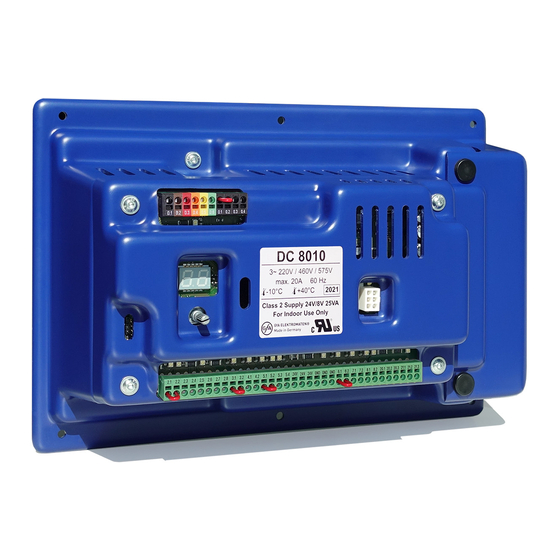
- Page 1 Installation instructions Door Control Unit DC 8010 Part number: 30005854 USA - Version: d/02.2021...
- Page 2 ▪ Read these instructions before using the product. ▪ Include these instructions when passing on the product to third parties. Contact: GfA ELEKTROMATEN GmbH & Co. KG Wiesenstraße 81 40549 Düsseldorf www.gfa-elektromaten.com info@gfa-elektromaten.com +49 211 / 500 90 0...
-
Page 3: Table Of Contents
General safety information ..........2 Storage and transport ............3 Product overview ..............3 Technical data ..............3 Overview of the DC 8010 ............ 4 Overview of the control unit ..........5 Status displays of the door control ........6 Mechanical installation ............8 Electrical installation ............ - Page 4 Readout of fault indications ........45 Readout of the cycle counter since last prog. change ..46 Readout of software version ........46 Reset to factory settings / use of GfA-Stick ..... 46 Maintenance and repair ............47 Fault indication ..............47 Maintenance ................52...
-
Page 5: Safety Chapter
1 Safety chapter 1.1 Explanation of symbols Safety note: Non-compliance will result in death or severe injury. Safety note: Non-compliance may result in death or severe injury. Safety note: Non-compliance may result in injury. Note: Non-compliance may result in property damage and impairment of the product‘s functionality. -
Page 6: Specified Use
1.3 Specified use The door control is intended for installation in a force-actuated door that is driven by a GfA ELEKTROMATEN (door drive unit) with digital limit switch (DES). The control may be used only indoors and exclusively for vertically moving doors. -
Page 7: Storage And Transport
2 Storage and transport Store the door control in the original packaging in a dry place. The temperature may be between 32 F (0 °C) and 122 F (+50 °C). The humidity must not exceed 93 %. Do not stack anything on the door control. Transport the door control in the original packaging. -
Page 8: Overview Of The Control Unit
Terminals X1: Operating voltage Terminals X3: Emergency STOP Terminals X29: Relay for separate Terminals X2: Safety edge brake control Selector switch Connector for GfA Bluetooth stick Connector for membrane push Terminals X21: potential-free button form C relay (NO/NC) Display Terminals X20: potential-free... -
Page 9: Status Displays Of The Door Control
3.3 Status displays of the door control Status displays The following explains the symbols that the display of the door control can represent. ▪ The display of the door control consists of a double-digit seven-segment-display. ▪ The display can show symbols, letters, or numbers. ▪... - Page 10 Status displays during operation Description Display Standby. A movement command or pressing a pushbutton exits the standby mode. Preset maintenance cycle counter has been reached. See menu item Display does not light up. Indicates a short circuit or overload of the 24V DC supply voltage.
-
Page 11: Mechanical Installation
4 Mechanical installation The following describes how to mount the door control unit on the wall. Danger due to unattended door movement! The operation of the door without line of sight leads to dangerous situations for other persons. ▪ Mount the door control with a clear view of the door. Damage to components due to extreme ambient conditions! Extreme ambient conditions at the installation site can damage... -
Page 12: Electrical Installation
5 Electrical installation The following describes how to connect the door control to the door drive unit and the power grid, and how to attach external devices. Follow local installation regulations during the entire electrical installation. Danger to life due to electric shock! Improper installation may result in death or severe injury from electrical current. -
Page 13: Fuses
5.1 Fuses The door control has four fuses. Fuses F1 to F3 are motor fuses. Fuse F4 is the control fuse. Risk of fire! Fuse F4 must have a current value of 500 mA. Otherwise, the function of the fuse is not given. The current value of fuses F1-F3 is 20 A. -
Page 14: Connecting Motor To Door Control
2. Attaching the connecting cable to the DC 8010 ▪ The wires and terminals are colored. Connect the wires of the DES connecting cable (1) to the matching color of the terminals D.1 to D.6 (2). Color Wire/ Terminal Function... - Page 15 ▪ Terminal M1 to phase U1 ▪ Terminal M2 to phase V1 ▪ Terminal M3 to phase W1 ▪ Connect the ground terminal of the DC 8010 (3) to the grounding screw (2). ▪ Replace the cover of the terminal box and the terminal cover.
-
Page 16: Motor Cable Conductor Size (Awg)
5.4 Motor cable conductor size Drives with AC motor Drives Mains Voltage Control Ambient Temperature Ambient Temperature Unit Correction Factor to Correction Factor to Fuse 30°C / 86°F 40°C / 104°F [Based on Temperature [Based on Temperature Rating of Conductor Rating of Conductor 75°C / 167°F] 75°C / 167°F]... -
Page 17: Setting The Operating Voltage
5.5 Setting the operating voltage Danger to life due to electric shock! ▪ Carry out the following steps only in a de-energized state. You select the local operating voltage with a jumper on terminals X1. Selectable: 220V, 460V or 575V (+/- 10%). ▪... -
Page 18: Connecting External Devices
6 Connecting external devices The following explains how to connect external devices to terminals X to X29 of the door control. Danger to life due to electric shock! Improper installation may result in death or severe injury from electrical current. ▪... -
Page 19: X: Power Supply 24V Dc
X: Power supply 24V DC Connect external devices that require 24V DC to terminals X 24V/GND 0V. For example, photocells, radio receivers and relays. Damage to components! The total current consumption of external devices must not exceed 500mA. X2: Safety edge The door control detects three different types of safety edges: electrical, pneumatic, and optical ones. - Page 20 Pneumatic safety edge Connect the pneumatic safety edge with a terminal resistance of 1k2 (3) as follows: ▪ Install the product according to the manufacturer‘s instructions. ▪ Connect the cables of the product to terminals X2.3 and X2.4 of the door control (2) as shown (1). ▪...
- Page 21 Optical safety edge Connect an optical safety edge with 2 or 3 wires as follows: Optical safety edge with 2 wires: ▪ Install the product according to the manufacturer‘s instructions. ▪ Connect the brown cable (1) to terminal X2.3. ▪ Connect the green cables (2) to terminal X2.4. ▪...
-
Page 22: X2: Door Safety Switch
X2: Door safety switch You can connect a door safety switch for a pass door or a slack-rope switch to terminals X2.1/2.2. ▪ Install the product according to the manufacturer‘s instructions. ▪ Connect the product as shown. With the door safety switch open and simultaneousmovement command, the door stops, and fault indication appears. -
Page 23: X4: Switch For Automatic Closing
X4: Switch for automatic closing You can connect a switch for automatic closing time to terminals X4.1/4.2. With menu item , you select a time between 1 and 240 seconds after which the door closes automatically. The switch activates and deactivates this function. The programmed time remains stored. -
Page 24: X5: External Control Device
X5: External control device You can connect an external control device for operating the door to terminals X5.1 to X5.4. Danger due to unattended door movement! The safety devices are deactivated in operating mode hold-to- run. People or objects in the movement path are not detected. ▪... -
Page 25: X6: Photocell
X6: Photocell You can connect a reflective or through beam photocell to terminals X6.1/X6.2 as well as 24V and GND. Use only photocells of mode „light switching“. To operate a photocell at the door, select option .3, .4, 1.3 under menu item (operating mode). You can set further photocell functions under menu item ▪... -
Page 26: X7: Radio Receiver / Pull Switch
X7: Radio receiver / pull switch You can connect a pull switch or radio receiver to terminals X7.1/X7.2. The switching contact must be potential-free. Radio receiver / pull switch ▪ Install the product according to the manufacturer‘s instructions. ▪ Connect the product as shown. ▪... -
Page 27: X8: Switch For Intermediate Open
X8: Switch for intermediate open You can connect a switch for intermediate open of the door to terminals X8.1/X8.2. You program the door positions of intermediate open with menu item 1.6. The switch activates this function. With an OPEN command, the door moves to the stored door position. -
Page 28: X29: Separate Control For Magnetic Brakes
Connecting trafficlight ▪ Install the product according to the manufacturer‘s instructions. ▪ Connect the product as shown. You can connect traffic lights to terminals X20.1/ X20.2 or X21.1/X21.2. ▪ Activate the product after completion of the electrical ▪ installation with menu items P 2.8. We recommend the use of LED trafficlights. X29: Separate control for magnetic brakes If the door drive unit has a magnetic brake you have to connect the brake to terminals X29.1-X29.3 to control the brake independently. -
Page 29: Setting The Final Limit Positions
7 Setting the final limit positions The following explains how to set the final limit positions of the door at the initial commissioning. If you have already connected a safety edge, the pre-limit is automatically set with the final limit positions. You can correct the final limit positions later with menu items 1. 1 P 1.4 You can correct the final limit position of the safety edge’s pre-limit with menu item Setting the final limit positions 1. Turn on power: ▪ Turn on the power using the main switch for the following steps. 2. - Page 30 4. Setting the final limit position OPEN: ▪ Press the OPEN button until the door has reached the desired position. Press the Button for at least one second. ▪ Save the final limit position OPEN by pressing the STOP button for 3 seconds. The display changes as shown in the figure. 5. Setting the final limit position CLOSE: ▪ Press the CLOSE button until the door has reached the desired position.
-
Page 31: Programming
8 Programming This chapter explains how to program the door control and which menu items are available. Before you can start programming, you must have set the final limit positions. Programming the door control 1. Start programming: ▪ Press the selector switch for 3 seconds.The display changes 2. Select the menu item: ▪... -
Page 32: Operating Mode
0.1 Operating mode With this menu item, you select the operating mode for moving the door during OPEN operation and CLOSE operation. When selecting the option, note the following: ▪ the number of safety devices and safety edges at the door. ▪... -
Page 33: Output Rotating Direction
0.2 Output rotating direction Use this menu item to change the output rotation direction of the door drive unit. Changing the output rotating direction Select the options with the OPEN or CLOSE button Maintaining the output rotation direction. Exit the menu item by pressing the selector switch. Changing the output rotating direction. -
Page 34: 1.5 Fine Correction Of Final Limit Positions
1.3 - 1.5 Fine correction of final limit positions Use this menu item to modify the final limit positions of the door that have been already set. No door movement takes place during fine correction. With menu items you can select the levels -9 to +9. Proceed step by step. Fine correction of final limit position OPEN Fine correction of final limit position CLOSE Fine correction of the safety edge‘s pre-limit _.9 - _ .9 _.9 = Correction in direction of final limit position CLOSE _ .9 = Correction in direction of final limit position OPEN... -
Page 35: 1.8 Switching Position Of Relays
1.7/1.8 Switching position of relays X20/X21 You only have to teach-in this switching position if you want to use the options of menu item 1. 1 With this menu item you can set the door position in which relays X20 and X21 switch. To use this function, you must set menu item P 2.7/P 2.8 and connect a device to X20 and/or X21. -
Page 36: Automatic Closing
2.3 Automatic closing With this menu item, you can select a time between 1 and 240 seconds after which the door closes automatically. For this purpose, you must activate an operation mode (menu item ) with the option self-hold OPEN/CLOSE. You can connect a switch for activating and deactivating this function to terminals X4.1 and X4.2. -
Page 37: Reaction Of Automatic Closing To Photocell
2.4 Reaction of automatic closing to photocell Use this menu item to stop automatic closing when the photocell is activated. This requires a photocell connected to terminals X6 and activation of menu item In operating mode ( hold-to-run, this menu item has no 0.1) effect. -
Page 38: Limiting Reversals
2.5 Limiting reversals Activate this menu item only if automatic closing is enabled. When automatic closing is enabled, the door moves to final limit position CLOSED after the set time. The door reverses when hitting an obstacle during movement. This means that the door changes the direction of movement and moves to the final limit position OPEN. Thanks to automatic closing, the door tries to close again after the set time has elapsed. -
Page 39: Radio And Pull Switch Functions
2.6 Radio and pull switch functions Use this menu item to select how the door responds to a command from the radio or pull switch button. To use this option, a radio or pull switch button must be connected to terminals X7. If you activate option and automatic closing , the door... -
Page 40: 2.8 Relay Functions Of
2.7/2.8 Relay functions of X20/X21 Use menu item to control the function of X20. Use menu item to control the function of X21. Both menu items have the same options. Terminals X20 und X21 are potential-free relay contacts. Relay functions of X20 Relay functions of X21 ►... -
Page 41: Specifying Control Device For Intermediate Open
2.9 Specifying control device for intermediate open Use this menu item to specify the control devices for approaching intermediate open. You must first set a position for intermediate open with menu item To switch intermediate open off and on, a switch must 1.6. be installed on X8. You can connect further control devices for intermediate open to X7 or X5. If an OPEN command is issued using the activated control devices, the door moves into intermediate open. -
Page 42: Force Monitoring Of Sectional Doors
3.1 Force monitoring of sectional doors Activate this menu item only if you operate a sectional door with counter-balancing. Force monitoring detects whether the door also lifts people. Force monitoring is active from an opening width of approx. 2“ (5cm) to 79“ (2m). Slowly advancing changes, such as decreasing spring tension, are compensated automatically. -
Page 43: Deactivation Of The Photocell
3.2 Deactivation of the photocell Components on the door (e.g. spiral cables) may interrupt the photocell always in the same position. A fault indication appears. Use this menu item for setting the position. During CLOSE operation, the photocell will be deactivated from this position onwards. -
Page 44: Shorten/Lengthen The Reversing Time
3.8 Shorten/lengthen the reversing time Use this menu item to shorten or lengthen the reversing time when a safety device is activated. Reversing time is the time it takes for the door to switch from CLOSE operation to OPEN operation. Lengthening the reversing time protects the door mechanism. -
Page 45: 4.9 Frequency Inverter Functions
4.1 - 4.9 Frequency inverter functions The following menu items are only visible and applicable if the door drive unit is equipped with a GfA original operator mounted frequency inverter. Increasing / decreasing the output speed Use this menu item to change the output speed of the door drive unit equipped with a frequency inverter. - Page 46 Acceleration to output speed OPEN/CLOSE With menu items , you increase/decrease the time in steps required by the door drive unit for accelerating to the specified output speed 4.1 - 4.3 Increase / decrease acceleration OPEN Increase / decrease acceleration CLOSE No change = Highest acceleration = Lowest acceleration 0.5 - 3.0 Braking With menu items , you increase/decrease the...
-
Page 47: 8.6 Setting The Maintenance Cycle Counter
8.5/8.6 Setting the maintenance cycle counter With these menu items, you set a reminder for the maintenance of the door. The maintenance cycle can be set between 1,000 and 99,000 cycles. The counter decreases by 1 every time the door reaches the final limit position OPEN. When the counter reaches the value 0, the setting from menu item is activated. -
Page 48: Readout Of Cycle Counter
9.1 Readout of cycle counter With this menu item, you can read out the cycle counter of the door control. The counter increases by 1 every time the door reaches the final limit position OPEN. It is not possible to reset the cycle counter. Readout of cycle counter After selecting the menu item, the display changes 7 times to show a 7-digit number. -
Page 49: Readout Of The Cycle Counter Since Last Prog. Change
The example below shows 1,000,000 cycles. 9.4 Readout of software version This menu item displays the software version of the door control. For drive units with GfA frequency inverter, the software version of the motor is shown as well. Readout of software version The display changes and shows the number of the software version. -
Page 50: Maintenance And Repair
9 Maintenance and repair The following explains how to maintain the door control and correct faults. 9.1 Fault indication The following describes fault indications and how to correct them. In case of a fault indication, the display shows an F. alternating with a number. - Page 51 Faults of safety devices Causes of faults Fault correction Anzeige wechselt zwischen F. und Ziffer ▪ No safety edge detected. ▪ Check wiring of the safety edge. ▪ Terminals X6 are open. ▪ Check alignment of the photocell. 2. 1 ▪ Photocell activated. ▪ Check connecting cable for interruption. ▪...
- Page 52 Fault at limit switch Fault description Fault correction Display alternates between F and number ▪ DES: emergency limit ▪ Retract the door in de-energized state with the 3. 1 switch OPEN reached. emergency manual operation. ▪ DES: emergency limit ▪ Retract the door in de-energized state with the switch CLOSE reached.
- Page 53 Fault of door movement Fault description Fault correction Display alternates between F and number ▪ Connection to digital limit ▪ Check plug and connecting cable of DES switch (DES) could not be established. ▪ Fault in door movement, ▪ Check door drive unit for stalling. exceeding the movement Danger of the door dropping! duration...
- Page 54 Frequency inverter fault These fault indications appear only for door drive units with with frequency inverter. Fault description Fault correction Display alternates between F and number ▪ Closing speed is too high ▪ Check door mechanism for stiffness. ▪ For doors with counter-balancing only: check for spring breakage.
-
Page 55: Maintenance
Faults when setting the final limit positions Fault description Fault correction ▪ When setting the final ▪ Reset door control to factory setting ( limit positions, the travel All settings will be lost! distance was smaller than ▪ When resetting the final limit positions, move the smallest possible the door for at least one second before storing the position.
Need help?
Do you have a question about the DC 8010 and is the answer not in the manual?
Questions and answers