Table of Contents
Advertisement
Quick Links
Advertisement
Table of Contents

Related Manuals for Carbatec BS-X3453C


Summary of Contents for Carbatec BS-X3453C
- Page 1 WARRANTY OWNERS MANUAL PROFESSIONAL 2250W - 345MM BANDSAW BS-X3453C...
-
Page 2: Table Of Contents
TABLE OF CONTENT 1. SPECIFICATIONS ........................1 2. WARNINGS ............................ 2 3. SAFETY INSTRUCTION FOR MACHINERY ................. 3 4. IDENTIFICATION ........................4 FRONT SIDE OF BAND SAW ....................4 REAR OF BAND SAW ......................5 5. OPERATING INSTRUCTION ..................... 6 LIFTING AND PLACING ...................... -
Page 3: Specifications
1. SPECIFICATIONS Horse Power Power Requirement 230V, 1PH, 50HZ Switch CE and Emergency Stop Switch Cutting Height 14"(355mm) Max. Cutting Width 13-1/2"(340mm) Max. Cutting (with Rip Fence) 12"(300mm) Saw Blade (L) 121.2"/3078mm Saw Blade (W) 1/8" to 3/4" (Standard 3/8") Saw Blade Speed 655 M/min. -
Page 4: Warnings
2. WARNINGS Misuse of this machine can cause serious injury. this machine can cause serious injury. Never leave machine runn unning while you are away from it. − − Always shut off the mach chine when not in use. For safety, machine must be set up, use ed and serviced −... -
Page 5: Safety Instruction For Machinery
GENERAL ELECTRICAL CAUTIONS Caution: This saw should be grounded in accordance with the National For circuits which are far away from the electrical Electrical Code and local codes and ordinances. This work should service box, the wire size must be increased in order to deliver be done by a qualified electrician. -
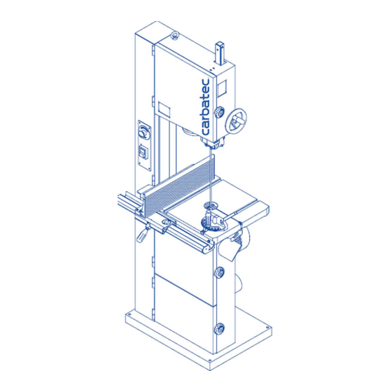
Page 6: Identification
4. IDENTIFICATION Throughout this document, we make reference to various systems Where detailed illustrations for various subsystems will be helpful, and components on the saw. The two illustrations on these pages will you will find these illustrations accompanying the specific teat for provide you with an overall frame of reference for the location and each subsystem and its components. -
Page 7: Rear Of Band Saw
REAR OF BAND SAW... -
Page 8: Operating Instruction
5. OPERATING INSTRUCTION OPERATING INSTRUCTION LIFTING AND PLACING Place lifting hook through eye bolt. (see Figure 1) Place lifting hook through eye bolt. (see Figure 1) Use a 2,000KGS wrecker to hang up the machine Use a 2,000KGS wrecker to hang up the machine Eye Bolt Eye Bolt to suitable place. -
Page 9: Assembling Rip Fence
ASSEMBLING RIP FENCE 1. Install fence support. Use (1)M6 flat washer and (2) M6 hex socket bolt.(see Figure 7) 2. Install the fence rail to the table. Use (1) two Fence Support M6 spring washers (2) two M6 hex head bolts (3) two M6 flat washers.(see Figure 8) 3. -
Page 10: Adjusting Upper Blade Guide Assembly
ADJUSTING UPPER BLADE GUIDE ASSEMBLY 1. Set the bearing of upper and lower blade guide within approx. 0.5mm of the blade. Make sure the bearing and the back of the blade approx. 0.5mm. Figure 12 (see Figure 12 and Figure 13) 2. - Page 11 TABLE PARALLEL ADJUSTMENT Insert table pin into the table groove.(Figure 16) Figure 16 Use the ruler gauge to put it on the table. (Figure 17) Adjust the position of table pin (adjust the depth of the pin) and adjust the parallel of the table by using the feller gauge.
-
Page 12: Miter Gauge Adjustment
MITER GAUGE ADJUSTMENT Place the miter gauge in the table slot. Loosen the clamp screw on the miter gauge. Adjust the desired angle of cutting on the miter gauge. Tighten the clamp screw. (see Figure 20) Figure 20 SAFETY DEVICE Limit switch (see Figure 21) inside the machine body for cutting off the power while door opening during operation. -
Page 13: Parts List
6. PARTS LIST MODEL NO. SBW-3501H1... - Page 20 TRUNNION SUPPORT BRACKET ASM (AB135250)
- Page 22 GRUIDE BRACKET ASM (AB135530)
- Page 24 MITER GAUGE ASSM (AB198101)
- Page 25 SAW BLADE ADJUSTMENT ASM – UPPER (AB135092B)
- Page 26 SAW BLADE ADJUSTMENT - LOWER (AB135095C)
- Page 27 UPPER WHEEL ASM (AB130466)
- Page 28 LOWER WHEEL ASM (AB130463)
-
Page 29: Wiring Diagram
7. WIRING DIAGRAM... - Page 30 Tools & Machinery Maxis Distribution Pty Ltd ABN 93 605 273 989 info@maxis.com.au Phone: 1300 767 366 International: +61 3292 0392 128 Ingleston Road, Wakerley Queensland Australia 4154 www.maxis.com.au...
Need help?
Do you have a question about the BS-X3453C and is the answer not in the manual?
Questions and answers