Table of Contents
Advertisement
Quick Links
Advertisement
Table of Contents

Subscribe to Our Youtube Channel
Related Manuals for Carbatec BS-345H


Summary of Contents for Carbatec BS-345H
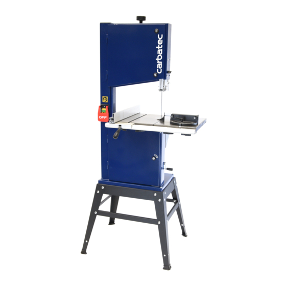
- Page 1 WARRANTY OWNERS MANUAL CARBATEC 345mm BANDSAW BS-345H...
-
Page 2: General Health & Safety Guidance
General Health & Safety Guidance Ensure that you carefully read and fully understand the 6. The machine should be level and stable at all times instructions in this manual before assembly, installation and • When using a leg stand or cabinet base that is designed to be fitted to use of this product. - Page 3 General Health & Safety Guidance - cont. complete stop. • Use extra supports (roller support stands etc.) for any work pieces large enough to tip when not held down to the table top. • If the work area is to be left unattended, all machinery should be switched ‘OFF’...
-
Page 4: Additional Health & Safety For Bandsaws
General Health & Safety Guidance - cont. • Before each use of the machine, it should be carefully checked to 32. Have your machine repaired by a qualified person determine that it will operate properly and perform its • This machine complies with the relevant safety rules and standards intended function. -
Page 5: Stand & Wheel Kit Assembly
3. Stand & Wheel Kit Assembly 3.1 Stand & Wheel Kit Assembly Fig.3.1 CAUTION! The machine is heavy. Additional help or a suitable lifting device or support will be required for lifting the machine onto the stand. The stand and wheel kit comes as a self assembly unit, Fig.3.1. Stand 1. - Page 6 3. Stand & Wheel Kit Assembly - cont. Fig.3.2 Fig.3.6 LONG MID BRACE SUPPORT Note: When assembling this legstand do not fully tighten the nuts and bolts until the assembly is complete. When fitting the optional pedal wheekit during initial assembly of the bandsaw, please do so before attaching the bandsaw to the leg stand to ensure greater safety and ease of fitment.
- Page 7 3. Stand & Wheel Kit Assembly - cont. 1. Feed the long fixing bolts up through the Fig.3.10 stand and secure the four corners using the washers and bolts provided Fig.3.10. Once LONG FIXING BOLTS this is achieved the whole stand can be fully tightened ready for the bandsaw to be fitted.
- Page 8 3. ASSEMBLY Fig. 1 3.1 Initial Assembly The machine is supplied partly assembled. Prior to use, the following items have to be fitted. Bandsaw table, Rip fence guide and Crank handle. 3.2 Fitting the table Tools Required: - 13mm Wrench Insert the M8 x 50 coach bolt and square plastic insert (A) through the slot on the upper trunion casting (B) and, temporarily, screw on the...
- Page 9 3.4 Fitting the Crank Handle Fig. 5 Tools Required :- Flat bladed screwdriver 10mm wrench Attach the crank handle (A) to the belt tension crank arm with the M6 x 55 slotted cheese head screw and two M6 nuts. Fig. 5 3.5 Assembling the Rip Fence The rip fence on this bandsaw can be used on either side of the blade by fixing the rip fence...
- Page 10 3.8 Setting the table square to sawblade Fig. 9 Tools Required :- Small 90 º square (not supplied) The table can be set at 90º to the sawblade Fig. 9 by adjusting the table stop screw underneath the table. The table stop screw rests on the top of the lower wheel bandwheel housing.
-
Page 11: Dust Extraction
3.11 Stability of the bandsaw Fig.13 Before using the bandsaw, ensure the machines upright stability is satisfactory. The bandsaw has four Ø8mm holes (A) Fig. 13 in it’s base to allow it to be bolted to the floor or a bench or alternatively to the optional workstand. - Page 12 3.15 Replacing the bandsaw blade Isolate the machine from the supply by unplugging the 3 pin plug. Open the top and bottom bandwheel doors by turning the door locks (A) with a flat bladed screwdriver. Remove the Rip fence guide (B) from the front of the table by releasing the 4 winged screws (C).
- Page 13 3.16 Tracking the Bandsaw blade Fig. 19 Isolate the machine from the supply by unplugging the mains plug. Set the tracking of the blade before setting the blade guides. Once the blade is fitted and tensioned, track the blade by turning the upper bandwheel by hand and adjusting the tracking knob (F) Fig.
- Page 14 3.18 Adjusting the Cutting Height Fig. 23 To adjust the cutting height release the winged nut (A) Fig.23 and move the upper blade guide and guard assembly (B) Fig. 23 so that it provides approx 2 - 3mm clearance above the workpiece. When set correctly re-tighten winged nut (A).
-
Page 15: Operation
4. OPERATION The blade cuts on a continuous downstroke. Slowly feed the workpiece towards the blade, putting only light pressure on it. With both hands, firmly hold the workpiece down on the table, and feed it towards the blade slowly, using the push stick supplied, keeping your hands away from the blade. For best results the blade must be sharp. -
Page 16: Troubleshooting
6. TROUBLESHOOTING WARNING: FOR YOUR OWN SAFETY, ALWAYS TURN OFF THE MACHINE AND UNPLUG BEFORE CARRYING OUT ANY TROUBLESHOOTING. TROUBLE PROBABLE CAUSE REMEDY The machine does not work 1. No power supply. - Check the cable for breakage. when switched on. - Check the fuse. -
Page 17: Part List
8. PART LIST REF. No. DESCRIPTION DESCRIPTION c r i p i l s i n l - r y l b i r a t f a f l e o l - i k c e i r t a l i r p r o f... - Page 18 - 13 -...
- Page 21 1 year from date of sale. Carbatec Pty Ltd ABN 84 010 706 242 info@carbatec.com.au | Phone 1800 658 111 | www.carbatec.com.au...
- Page 22 Carbatec Pty Ltd ABN 84 010 706 242 info@carbatec.com.au Phone: 1800 658 111 128 Ingleston Road, Wakerley Queensland Australia 4154...
Need help?
Do you have a question about the BS-345H and is the answer not in the manual?
Questions and answers