
Subscribe to Our Youtube Channel
Related Manuals for Carbatec TS-DST1600P


Summary of Contents for Carbatec TS-DST1600P
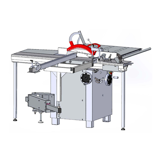
- Page 1 12” (305mm) Deluxe Sliding Table S aw T S - D S T 1 6 0 0 P I N S T R U C T I O N M A N U A L CA RBAT E C .C OM .AU...
-
Page 2: Introduction
Carbatec to keep you woodworking, as promised. We look forward to sharing in your woodworking journey! If you have any questions about our products or service, please call us on 1800 658 111 or email us at info@carbatec.com.au Find us on social media facebook.com/Carbatec instagram.com/Carbatec... - Page 3 TS-DST1600P WELCOME MODEL MJ12-1600E-M 12” SLIDING TABLE SAW MANUAL This table saw will require some assembly. Remove parts from all of the cartons and lay them on a clean work surface. CAREFULLY READ THE INSTRUCTION MANUAL BEFORE USE THE MACHINE KEEP THIS INSTRUCTION MANUAL FOR FUTURE REFERENCE.
-
Page 4: Key Information
Lot No.: Serial No.: DATE OF PURCHASE: Date: Made for: CARBATEC PT Y LTD Brisbane - Australia F O R TEC H N I CA L SU P PO R T C A L L 1 8 00 658 11 1... -
Page 5: Table Of Contents
Changes and improvements may be made at any time, with no obligation on the part of Carbatec to modify previously delivered units. Reasonable care has been taken to ensure that the information in this manual is correct, to provide you with the guidelines for the proper safety, assembly and operation of this machine. -
Page 6: Safety Instructions - General
Australian/New Zealand Standards to ensure their compliance with all mandatory standards and regulations (applicable at time of original sale). Carbatec Pty Ltd are registered as a responsible supplier with relevant Australian government departments and our products are registered on the EESS & ACMA database. - Page 7 TS-DST1600P SAFETY INSTRUCTIONS GENERAL SAFETY Operating a power tool can be dangerous if GROUND ALL TOOLS. If the tool is supplied safety and common sense are ignored. The with a 3-prong plug, it must be plugged into operator must be familiar with the operation of a 3-contact electrical receptacle.
- Page 8 TS-DST1600P GENERAL SAFETY ALWAYS UNPLUG THE TOOL FROM THE MAINTAIN TOOLS WITH CARE. Always ELECTRICAL RECEPTACLE keep tools clean and in good working order. when making adjustments, changing parts or Keep all blades and tool bits sharp, dress performing any maintenance.
-
Page 9: Safety Instructions - Electrical
TS-DST1600P SAFETY INSTRUCTIONS avoid prolonged contact with dust. Allowing enough to carry the current your product will dust to get into your mouth or eyes, or lay on draw, and with compatible pin configuration your skin may promote absorption of harmful and connections. -
Page 10: Safety Instructions - Table Saw
TS-DST1600P 1.2 Safety instructions for table saw Serious cuts, amputation, or death can occur from contact with rotating saw blade during operation. Workpieces, broken blades, or flying particles thrown by blade can blind or strike operators or bystanders with deadly force. To reduce the risk of these hazards, operator and bystanders must completely heed the hazards and warnings below. - Page 11 TS-DST1600P SAFETY INSTRUCTIONS DAMAGED SAW Damaged saw blade teeth can become deadly projectiles. Never use BLADES blades that have been dropped or damaged. CUTTING CORRECT Cutting metal, glass, stone, tile, etc., increases risk of operator injury MATERIAL due to kickback or flying particles. Only cut natural and man-made wood products, laminatecovered wood products, and some plastics.
- Page 12 TS-DST1600P ▲ Never, for any reason, place your hand behind the blade. Should kickback occur, your hand will be pulled into the blade, which could cause amputation. ▲ Use a push stick to keep your hands farther away from the moving blade. If a kickback occurs, the push stick will most likely take the damage that your hand would have received.
-
Page 13: Specifications
TS-DST1600P SPECIFICATIONS 3. Assembly This machine was carefully packaged for safe transport. When unpacking, separate all enclosed items from packaging materials and inspect them for shipping damage. Transport the table saw in its packing crate to a place near its final installation site before unpacking it. - Page 14 TS-DST1600P L. Small extension table O. Blade guard M. Large extension table N. Hose Support P. Hose Q. Push block R. Push stick Note: The machine has a tool kit for which is S. Wrench 13x16 16x18 T. Arbor lock tool convenient for storing the spanners, hex U.
- Page 15 TS-DST1600P ASSEMBLY 3.4 Placement location Consider the largest size of workpiece that will be processed through this machine and provide enough space around the machine for adequate operator material handling or the installation of auxiliary equipment. With permanent installations, leave enough space around the machine to open or remove doors/covers as required by the maintenance and service described in this manual.
- Page 16 TS-DST1600P 3.5.2 To assemble machine Assemble the sliding table: 1. Place sliding table on cabinet. 2. Slide the table forward and fasten the bolt in the hole of the carriage, and then slide the table backwards and fasten another bolt.
- Page 17 TS-DST1600P Install the small extension table: Remove the hexagon socket screws on the main cast iron table and then fasten the small extension table on the main table by these screws. By adjusting the positions of the screws, make the small extension table to be level with the upper and side surfaces of the main cast iron table.
- Page 18 TS-DST1600P Assemble the rip fence assembly: 1. Remove the screws on the side of the main table and large extension table, then fasten the rip fence scale on the two tables. Adjust the positions of the screw, to make the scale be parallel to the table.
- Page 19 TS-DST1600P MACHINE SETUP Install the cross cut table assembly: 1. Put the shaft of the support arm into the hole under the cross cut table. 2. Align T-nut on crosscut table with T-slot in face of sliding table, then slide crosscut table into position on sliding table and tighten crosscut table lock lever.
- Page 20 TS-DST1600P Install blade guard on riving knife. Loosen the handle of the blade guard and move the locking bolt to the right. Make the middle part of the locking screw coincide with the guard’s slot, then install the blade guard on the riving knife. Adjust the locking...
- Page 21 TS-DST1600P ADJUSTMENTS Note: The blade is fitted on the machine well already, but please check it carefully before running! Tilt blade assembly to 0, then slide sliding table forward all the way until you can open lower blade cover and access blade arbor.
-
Page 22: Operation
TS-DST1600P 4. Operation The purpose of this overview is to provide the novice machine operator with a basic understanding of how the machine is used during a typical operation, so the controls/components discussed later in this manual are easier to understand. - Page 23 TS-DST1600P ▲ Excessive Warping: Workpieces with excessive cupping, bowing, or twisting are dangerous to ▲ cut because they are unstable and may move unpredictably when being cut. ▲ Minor Warping: Slightly cupped workpieces can be safely supported with cupped side facing ▲...
- Page 24 TS-DST1600P not be used if it gets in the way of making a safe cut. Use good judgment! In general, the blade guard MUST remain installed on the saw—unless a specific operation requires its removal. If the blade guard is removed for specific operations, always immediately replace it after those operations are complete.
- Page 25 TS-DST1600P OPERATION 4.5 Changing blade This saw performs best with high-quality sharp blades. Whenever the blades become dull, replace or have them sharpened. To change the blade: 1. Disconnect saw from power. 2. Move blade tilt to 0° (blade 90° to table) and raise blade as far as it will go.
- Page 26 TS-DST1600P 4.6.1 Rip cutting with sliding table 1. Install crosscut fence on crosscut table, and rotate it until fence touches 90° stop bolt. 2. Check to make sure fence is at 90 and adjust it if necessary. 3. Slide fence so plastic block on end is next to blade teeth—this calibrates scale to zero—...
- Page 27 TS-DST1600P 5. Tighten lock handle to secure rip fence against fence base. 6. Pull up lock lever to loosen fence base on rail, position fence at correct distance away from blade (as needed for cut), then push down lock lever to lock fence base in position.
- Page 28 TS-DST1600P 4.7.3 Cross cutting using rip fence as a cut-off gauge 1. Install crosscut fence in rear mounting points and lock it in place. 2. Check to make sure fence is at 90 and adjust it if necessary. 3. Position rip fence for desired width.
-
Page 29: Maintenance
TS-DST1600P workpiece into the blade with steady downward and forward pressure. Supporting: A second push stick can be used to keep the workpiece firmly against the fence while cutting. When using a push stick in this manner, only apply pressure before the blade; otherwise, pushing the workpiece against or behind the blade will increase the risk of kickback. ... -
Page 30: Troubleshooting
TS-DST1600P 6. Troubleshooting Review the troubleshooting and procedures in this section if a problem develops with your machine. Symptom Possible Cause Possible Solution Machine does not 1. Power supply switched OFF or is at 1. Ensure power supply is switched on; ensure power supply has the correct voltage. - Page 31 SPARE PARTS TS-DST1600P Symptom Possible Cause Possible Solution Workpiece has burned 1. Sliding table is not parallel to blade. 1. Adjust sliding table parallel with the blade. edges, binds, or kicks 2. Riving knife is not aligned with the blade.
-
Page 32: Parts Diagram/Parts List
TS-DST1600P 7. Diagram and part list Part A Diagram and part list Description Size Description Size Wrench 13*16 Support plate Tool kit Hexagon socket screw M5X16 Allen wrench φ6 Positioning plate Wrench Hexagon head bolt M6X25 Allen wrench φ5 Nut M6 Allen wrench φ4... - Page 33 SPARE PARTS TS-DST1600P Part B Diagram C A RBATE C.C OM.AU...
- Page 34 TS-DST1600P Part B part list Description Size Description Size Flat key A4X12 Bush Hexagon socket screw M5X12 A5X20 Hexagon socket screw M6X12 Pulley Flat washer Saw seat Lifting hand wheel Bearing 6005Z2 Handle Screw M6X16 Lifting leadscrew Connecting rod Adjustable handle...
- Page 35 TS-DST1600P Part C Diagram and part list Description Size Description Size Lock bolt Locking handle M8X15 T nut Pusher Hose support Sliding block Handle Aluminum cover B Pressure plate Screw M4X8 Hexagon socket screw M10X60 Rubber hose Φ38 Sliding table...
- Page 36 TS-DST1600P Part D Diagram and part list Description Size Description Size Bolt Hexagon socket set screw M6X10 Bolt Pressure plate Rip fence Self-locking nut Ball bearing Pan head screw M6X12 Hexagonal shaft Scale seat Eccentric wheel Scale Screw Hexagon socket screw...
- Page 37 TS-DST1600P Part E Diagram and part list Description Size Description Size Pan head screw M6X12 Support plate Locking handle Sliding block Locking plate Short fence Handle Hexagon socket screw M6X10 Self tapping screw ST4X12 Scale 122-129 Front end cap Flat washer...
- Page 38 TS-DST1600P Part F Diagram and part list Description Size Description Size Hexagon head bolt M6X20 M6X20 Stop pin Long connecting plate Long positioning block End cap Hexagon socket screw M4X25 Hexagon socket screw M6X20 Self-locking nut Angle scale Crosscut table...
- Page 39 TS-DST1600P Part H Diagram and part list Description Size Description Size Support rod Flat washer Inner support arm Bearing 6202-2RZ/Z1 End cap Hexagon head bolt M8x25 Nut plate Hex nut Wheel Hexagon head bolt M10x30 Wheel sleeve Flat washer Felt 55x25...
- Page 40 TS-DST1600P Part J Diagram and part list Description Size Description Size Ball handle Pressing handle Flat washer Eccentric wheel Hexagon socket screw M5X8 Circlip for shaft Press block Shaft retaining ring End cap Spring Bolt M6X30 Mitre fence Swing arm...
-
Page 41: Wiring Diagram
TS-DST1600P 7.2 Wiring diagram 230V 50HZ 1PH: 220V 60HZ 1PH: 400V 50HZ 3PH: C A RBATE C.C OM.AU... - Page 42 TS-DST1600P NOTES PAGE F O R TEC H N I CA L SU P PO R T C A L L 1 8 00 658 11 1...
-
Page 43: Warranty
1. a copy of the order or receipt for the goods; 2. the serial or batch number printed on the A. We warrant that this Carbatec product will be free machinery manufacturing plate; and from defects caused by faulty workmanship or faulty materials for a period of 2 years from date of sale. - Page 44 CAREFULLY READ THE INSTRUCTION MANUAL BEFORE USE THE MACHINE KEEP THIS INSTRUCTION MANUAL FOR FUTURE REFERENCE. C a r b at e c P t y L td E info@carbatec.com.au AU 1800 658 111 NZ 0800 444 329 128 Ingleston Road, Wakerley,...
Need help?
Do you have a question about the TS-DST1600P and is the answer not in the manual?
Questions and answers