Table of Contents
Advertisement
Quick Links
Advertisement
Table of Contents

Related Manuals for Carbatec BS-245H


Summary of Contents for Carbatec BS-245H
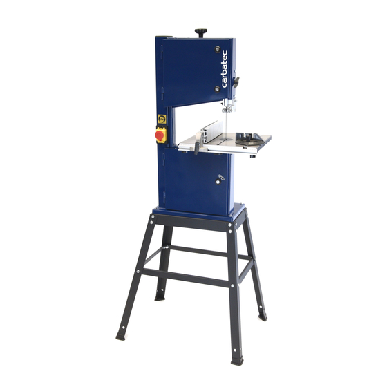
- Page 1 10” Bandsaw B S - 2 4 5 H M A N U A L C A R BAT E C .C O M . AU...
- Page 2 Aussie woodworkers. Backed by our no-fuss after-sales care and warranty support, you can trust Carbatec to keep you woodworking, as promised. We look forward to sharing in your woodworking journey! If you have any questions about our products or service, 1800 658 111 info@carbatec.com.au...
-
Page 3: What's In The Box
BS-245H WELCOME WHAT’S IN THE BOX The following items are provided in the shipping box: BS-245H 10” BANDSAW Fence Short top brace Fence rail Long top brace Main unit mounting bolts Short mid rail brace Feet Long mid rail brace... - Page 4 DATE OF PU RC H ASE : Made in for: CARBATEC PTY LTD Brisbane - Australian F O R TEC H N I CA L SU P PO R T C A L L 1 8 00 658 11 1...
-
Page 5: Table Of Contents
Changes and improvements may be made at any time, with no obligation on the part of Carbatec to modify previously delivered units. Reasonable care has been taken to ensure that the information in this manual is correct, to provide you with the guidelines for the proper safety, assembly and operation of this machine. -
Page 6: Safety Instructions - General
Carbatec products bearing the Regulatory Compliance Mark (RCM) have been tested in accordance with applicable Australian/New Zealand Standards to ensure their compliance with all mandatory standards and regulations (applicable at time of original sale). Carbatec Pty Ltd are registered as a responsible supplier with relevant Australian government departments and our products are registered on the EESS &... -
Page 7: Safety Instructions - Bandsaw 1 0 -1
BS-245H SAFETY INSTRUCTIONS GENERAL SAFETY READ this entire manual. LEARN how to Operating a power tool can be dangerous if safety and common sense are ignored. use the tool for its intended applications. The operator must be familiar with the GROUND ALL TOOLS. - Page 8 BS-245H GENERAL SAFETY WEAR PROPER CLOTHING. NEVER LEAVE A RUNNING TOOL UNATTENDED. Turn the power switch Do not wear loose clothing, gloves, neckties, or jewellery. These items can to the “OFF” position. Do not leave the get caught in the machine during tool until it has come to a complete stop.
-
Page 9: Safety Instructions - Electrical 1
BS-245H SAFETY INSTRUCTIONS SECURE ALL WORK. Use clamps or USE A PROPER EXTENSION CORD IN GOOD CONDITION. Use of extension jigs to secure the work piece. This is safer than attempting to hold the work cords should be avoided where possible. - Page 10 BS-245H SPECIFIC BANDSAW SAFETY NOTE: According to the applicable product liability law the manufacturer of this device is not liable for damages which arise on or in The device and packaging materials are connection with this device in case of:...
- Page 11 BS-245H SAFETY INSTRUCTIONS • Any other use exceeds authorisation. • Saw dust and wood chips can be The manufacturer is not responsible hazardous. Always wear AS/NZS for any damages resulting from approved personal protective gear unauthorized use; risk is the sole such as safety goggles, dust mask and responsibility of the operator.
- Page 12 BS-245H ELECTRICAL SAFETY CHECK WITH A QUALIFIED ELECTRICIAN or service personnel if you do not This tool must be grounded while completely understand the grounding in use to protect the operator from instructions, or if you are not sure the electric shock.
-
Page 13: Overview 1
BS-245H OVERVIEW OVERVIEW 10” BANDSAW OVERVIEW Blade tension knob Cast table Blade tracking knob Bottom blade guide Blade guard knob Bottom door lock Table tilt trunnion Stand Top door lock Bottom access door Blade guard lock knob Fence rail Top blade guide... -
Page 14: Specifications 1
SPECIFICATIONS BRAND Carbatec 375W (1/2HP) induction - MOTOR Regular 10 Amp plug SWITCH TYPE Magnetic NVR 1790mm BLADE LENGTH BLADE GUIDES Ball bearing with manual rise and fall BLADE RELEASE Standard tension release CUT DEPTH 125mm 1x63.5mm (2.5”) DUST PORT MINIMUM BLADE WIDTH 3.2mm (1/8”) - Page 15 BS-245H ASSEMBLY ASSEMBLY INSTRUCTIONS NOTE: When assembling this leg stand do not Fig. A1 tighten the nuts and bolts until the assembly is complete. STAND ASSEMBLY Using any one of the 4 legs, secure it to one of two long top braces with 2x short dome head bolt, washer and nuts.
- Page 16 BS-245H STAND ASSEMBLY Fig. A4 Use one preassembled leg section. Attach the 2 shorter top braces with 4x dome head bolts, washers and nuts. Fig. A4 Attach the 2 short mid rail braces with 2x dome head bolts, washers and nuts.
- Page 17 BS-245H ASSEMBLY FITTING TO THE STAND FITTING THE BANDSAW Fig. B1 TO THE STAND Push the 4x rubber feet on to the bottom of the stand legs. Fig. B1 From under the top of the stand frame, put the 4x long hex bolts...
- Page 18 BS-245H FITTING TO THE STAND Fig. B7 You may require assistance for the following step. Lift the main body up and onto the top of the stand. Be aware of the exposed bandsaw blade while lifting. Take care to align the 4x protruding...
- Page 19 BS-245H ASSEMBLY FINAL ASSEMBLY INSTALLING TO TRUNNION Fig. C1 Loosen the wing nut between the upper and lower trunnion, place into the horizontal position and re-tighten. Fig. C1 Slide the cast iron table (smooth side up) onto the trunion passing the blade through the table slot from the Fig.
- Page 20 BS-245H FINAL ASSEMBLY Fig. C5 To fit the supplied fence, prepare the two smaller wing knobs and fit with a washer to the outer left and right holes situated under the front leading edge of the cast iron table. These should be fitted with sufficient gap to allow the fence rail to slot in.
- Page 21 BS-245H ASSEMBLY ALIGNMENT & ADJUSTMENTS Fig. D ENSURE POWER IS DISCONNECTED FROM YOUR MACHINE BEFORE UNDERTAKING ANY ADJUSTMENTS OF ALIGNMENT. SETTING BLADE TO TABLE SQUARENESS Fig. D With the blade tensioned adequately (see Changing Saw Blades p. 24), adjust the blade trunnion by loosening the large wing nut, and adjust the Fig.
- Page 22 BS-245H ALIGNMENT & ADJUSTMENTS SETTING FENCE TO ZERO Fig. F Lock the fence so that it reads ZERO. If this position sees an excessive gap between fence and blade, or if the blade is pressing hard against the fence, proceed to adjust the fence position.
- Page 23 BS-245H ASSEMBLY Fig. G1 Set your blade tension first using the tension knob on the top of the cabinet, then adjust top and bottom saw guide bearings, and thrust (rear) bearings, so that they are not in contact with the saw blade (see Adjusting Blade Guide Bearings, p.24).
-
Page 24: Changing The Saw Blades
BS-245H CHANGING THE SAW BLADES ADJUSTING BLADE GUIDE Fig. H1 BEARINGS Adjust the top and bottom blade guide bearings by loosening the hex screw and moving the bearing so that it is approx 0.05-0.1mm (one or two sheets of paper) away from the blade. -
Page 25: Operation 2 5 -2
BS-245H OPERATION OPERATION Fig. J Reverse this process to fit new blade, ensuring the blade teeth are facing forward, and teeth are pointing DOWN in your right hand. Apply correct blade tension, and recheck tracking, alignment etc. as per instructions. - Page 26 BS-245H OPERATION Ensure you are wearing AS/NZS approved PPE (dust mask or respirator, eye protection and hearing protection). Remember to avoid placing your hands anywhere near the cutting area, and make sure you have push sticks, push blocks in close proximity.
- Page 27 BS-245H OPERATION Fig. L4 Continue feeding until your board is cut through. Controlling your cuts utilising feather boards will free up your hands, allowing you to safety reach around the rear to control the board exiting the blade. Fig. L4...
- Page 28 BS-245H OPERATION Fig. M1 Start the machine, waiting until it is running at full speed, before presenting the timber to the blade. Slowly advance the timber to the required line to begin cutting, slowly turning the timber to follow your pattern.
-
Page 29: Replacement Blades
BS-245H OPERATION Fig. M4 Miter cutting can be undertaken utilising the included miter gauge, set to the desired angle. Fig. M4 REPLACEMENT BLADES KEY No LENGTH (mm) WIDTH (mm) BBL-1790-3-14 1790 BBL-1790-6-6 1790 BBL-1790-6-10 1790 BBL-1790-10-6 1785 A 3mm x 14TPI blade will do very tight curves, in material up to approximately 12mm in thickness. -
Page 30: Maintenance 3
Take a clean cloth to wipe any cleaning residue, dirt or dust off the table. When it’s dry, apply a surface protectant. Carbatec offer many products for machine cleaning and care. • Check the cutting edges of the blades and replace if dull. Thoroughly clean the blades clean with either steel wool or a firm bristle brush if they are rusty or pitch covered. -
Page 31: Wiring Diagram
BS-245H WIRING DIAGRAM WIRING DIAGRAM C A RBATE C.C OM.AU... - Page 32 BS-245H PARTS DIAGRAM F O R TEC H N I CA L SU P PO R T C A L L 1 8 00 658 11 1...
- Page 33 BS-245H PARTS LIST PARTS LIST DESCRIPTION DESCRIPTION DESCRIPTION Band saw frame Washer Bearing bolt lower Door upper Hex. screw Motor Door lower Wing nut Motor pulley Upper wheel Hex. nut Table trunnion lower Bearing ball Knurled thamb screw Wheel pulley...
-
Page 34: Warranty 3
WARRANTY you must include in the email the following A. We warrant that this Carbatec product will be free information: from defects caused by faulty workmanship or faulty 1. a copy of the order or receipt for the goods;... -
Page 35: Troubleshooting
BS-245H TROUBLESHOOTING TROUBLESHOOTING TO PREVENT INJURY TO YOURSELF or damage to the bandsaw, turn the switch to the “OFF” position and unplug the power cord from the electrical receptacle before making any adjustments. PROBLEM LIKELY CAUSE(S) SOLUTION(S) The machine does No power supply. - Page 36 C a rbat ec P t y L t d E info@carbatec.com.au AU 1800 658 111 NZ 0800 444 329 128 Ingleston Road, Wakerley, Queensland Australia 4154 ABN 84 010 706 242 CA R BATEC .C O M .AU...
Need help?
Do you have a question about the BS-245H and is the answer not in the manual?
Questions and answers