Table of Contents
Advertisement
Quick Links
A l l t e s t I n s t r u me n t s , I n c .
5 0 0 C e n t r a l A v e .
F a r mi n g d a l e , N J 0 7 7 2 7
P : ( 7 3 2 ) 9 1 9 - 3 3 3 9
F : ( 7 3 2 ) 9 1 9 - 3 3 3 2
a l l t e s t . n e t
s s a l e s @ a l l t e s t . n e t
T h e t e s t & me a s u r e me n t
e q u i p me n t y o u n e e d a t
t h e p r i c e y o u w a n t .
A l l t e s t c a r r i e s t h e w o r l d ' s l a r g e s t s e l e c t i o n o f
u s e d / r e f u r b i s h e d b e n c h t o p t e s t & me a s u r e me n t
e q u i p me n t a t 5 0 % t h e p r i c e o f n e w .
O O u r e q u i p me n t i s g u a r a n t e e d w o r k i n g , w a r r a n t i e d , a n d
a v a i l a b l e w i t h c e r t i f i e d c a l i b r a t i o n f r o m o u r i n - h o u s e s t a f f
o f t e c h n i c i a n s a n d e n g i n e e r s .
• 1 0 + f u l l t i me t e c h n i c i a n s w i t h o v e r 1 5 0 y e a r s o f
s p e c i a l i z a t i o n
• 9 0 d a y w a r r a n t y & 5 d a y r i g h t o f r e t u r n o n a l l
e q u i p me n t
• • 1 - 3 y e a r w a r r a n t i e s f o r n e w a n d
p r e mi u m- r e f u r b i s h e d e q u i p me n t
• E v e r y u n i t t e s t e d t o O E M s p e c i f i c a t i o n s
• S a t i s f a c t i o n g u a r a n t e e d
Y o u h a v e p l a n s , w e w i l l h e l p y o u a c h i e v e t h e m.
A n y p r o j e c t . A n y b u d g e t .
t
G e t a q u o t e t o d a y !
C C a l l ( 7 3 2 ) 9 1 9 - 3 3 3 9 o r e ma i l s a l e s @a l l t e s t . n e t .
Advertisement
Chapters
Table of Contents

Related Manuals for Anritsu MP1570A


Summary of Contents for Anritsu MP1570A
- Page 1 T h e t e s t & me a s u r e me n t e q u i p me n t y o u n e e d a t t h e p r i c e y o u w a n t . A l l t e s t I n s t r u me n t s , I n c .
- Page 2 MP1570A SONET/SDH/PDH/ATM Analyzer Operation Manual Vol.1 Basic Operation SONET 15th Edition For safety and warning information, please read this manual before attempting to use the equipment. Keep this manual with the equipment. ANRITSU CORPORATION Document No.: M-W1720AE-15.0...
- Page 3 Safety Symbols To prevent the risk of personal injury or loss related to equipment malfunction, Anritsu Corporation uses the following safety symbols to indicate safety-related information. Ensure that you clearly understand the meanings of the symbols BEFORE using the equipment.
- Page 4 For Safety WARNING 1. ALWAYS refer to the operation manual when working near locations at which the alert mark shown on the left is attached. If the advice in the operation manual is not followed there is a risk of personal injury or reduced equipment performance.
- Page 5 Calibration 6. The performance-guarantee seal verifies the integrity of the equipment. To ensure the continued integrity of the equipment, only Anritsu service personnel, or service personnel of an Anritsu sales representative, should break this seal to repair or calibrate the equipment. If the performance-guarantee seal is broken by you or a third party, the performance of the equipment cannot be guaranteed.
- Page 6 For Safety WARNING Battery Fluid 8. DO NOT short the battery terminals and never attempt to disassemble the battery or dispose of it in a fire. If the battery is damaged by any of these actions, the battery fluid may leak. This fluid is poisonous. DO NOT touch the battery fluid, ingest it, or get in your eyes.
- Page 7 For Safety CAUTION Fuse Replacement 1. Always remove the mains power cable from the power outlet before replacing blown fuses. There is a risk of electric shock if fuses are replaced with the power cable connected. Always use new fuses of the type and rating specified on the rear panel of the instrument.
- Page 8 For Safety Class 1, 1M indicate the danger degree of the laser radiation specified below according to IEC 60825-1:2001. Class 1: Lasers that are safe under reasonably foreseeable conditions of operation, including the use of optical instruments for intrabeam viewing. Class 1M: Lasers emitting in the wavelength range from 302.5 to 4000 nm that are safe under reasonably foreseeable conditions of operation, but may be hazardous if the user employs optics...
- Page 9 For Safety Class I, IIa, II, IIIa, IIIb indicate the degree of danger of the laser radiation outlined below as defined by 21 CFR 1040.10:1995. Class I: Class I levels of laser radiation are not considered to be hazardous. Class IIa: Class IIa levels of laser radiation are not considered to be hazardous if viewed for any period of time less than or equal to 1 ×...
- Page 10 If this warning light does not turn on, the equipment may be faulty and for safety reasons should be returned to an Anritsu service center or representative for repair. The laser in the plug-in unit provided for this equipment is classified as Class 1, 1M according to the IEC 60825-1:2001 standard, or as Class I, IIIb according to the 21 CFR 1040.10:1995 standard.
- Page 11 For Safety Table 2 Laser Safety Classifications Based on FDA21 CFR 1040.10:1995 Max. Optical Pulse Width (s)/ Emitted Model Name Class Laser Aperture Output Power (W) * Repetition Rate Wavelength (nm) MP0111A 0.32 1310 Fig. 1 [1] MP0112A 1550 Fig. 1 [2] 0.32 1310 Fig.
- Page 12 For Safety Table 3 Indication Labels on Product (Ex: Label list) Type Sample Affixed to: Model Name MP0127A,MP0128A,MP0129A, MU150008A,MU150009A, Aperture Fig. 5, 6, 7 A MU150010A, MU150001A/B,MU150031A/C, MU150061A/B MP0112B, MP0127A,MP0128A,MP0129A, MU150008A,MU150009A, Explanation Fig. 3, 5, 7 B MU150010A MU150001A/B,MU150031A/C, MU150061A/B MP0111A,MP0112A,MP0113A, MP0112B, MP0127A,MP0128A,MP0129A,...
- Page 13 For Safety Laser Radiation Markings Fig. 1 Locations of Laser Beam Apertures and Affixed Labels CAUTION When only a Unit is purchased, an adhesive label is supplied with the Unit. Please, attach it to the place, shown above.
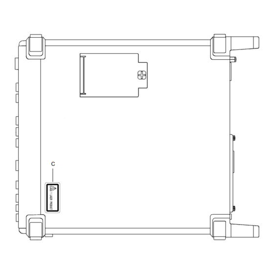
- Page 14 For Safety Fig. 2 MP0122B Front Panel of Unit and Top Panel of MP1570A (Products shipping besides U.S.A.) CAUTION When only a Unit is purchased, an adhesive label is supplied with the Unit. Please, attach it to the place, shown above.
- Page 15 For Safety Fig. 3 MP0122B Front Panel of Unit and Top Panel of MP1570A (Products shipping to U.S.A.) CAUTION When only a Unit is purchased, an adhesive label is supplied with the Unit. Please, attach it to the place, shown above.
- Page 16 For Safety Fig. 4 MP0127A, MP0128A, MP0129A, MU150008A, MU150009A, MU150010A Front Panel of Unit and Top Panel of MP1570A (Products shipping besides U.S.A.) CAUTION When only a Unit is purchased, an adhesive label is supplied with the Unit. Please, attach it to the place, shown above.
- Page 17 For Safety Fig. 5 MP0127A, MP0128A, MP0129A, MU150008A, MU150009A, MU150010A Front Panel of Unit and Top Panel of MP1570A (Products shipping to U.S.A.) CAUTION When only a Unit is purchased, an adhesive label is supplied with the Unit. Please, attach it to the place, shown above.
- Page 18 Invisible Laser radiation is Interlock emitted from this aperture Laser Fig. 6 MU150001A/B, MU150031A/C, MU150061A/B Front Panel of Unit and Top Panel of MP1570A (Products shipping besides U.S.A.) CAUTION When only a Unit is purchased, an adhesive label is supplied with the Unit.
- Page 19 Invisible Laser radiation is Interlock emitted from this aperture Laser Fig. 7 MU150001A/B, MU150031A/C, MU150061A/B Front Panel of Unit and Top Panel of MP1570A (Products shipping to U.S.A.) CAUTION When only a Unit is purchased, an adhesive label is supplied with the Unit.
- Page 20 For Safety Security Measure Functions The MP0127A, MP0128A, MP0129A, MU150001A/B, MU150008A, MU150009A, MU150010A, MU150031A/C, MU150061A/B are provided with the following security measure functions to prevent the possibility of infliction bodily injury on operators. • Laser cut-off When the cable is disconnected from the optical output section, the protective cover closes and the laser emission stops.
- Page 21 Back-up Battery the memory. This battery must be replaced by service personnel when it has reached the end of its useful life; contact the Anritsu sales section or your nearest representative. Note: The battery used in this equipment has a maximum useful life of 7 years.
- Page 22 In addition, this warranty is valid only for the original equipment purchaser. It is not transferable if the equipment is resold. Anritsu Corporation shall assume no liability for injury or financial loss of the customer due to the use of or a failure to be able to use this equipment.
- Page 23 Notes On Export Management This product and its manuals may require an Export License/Approval by the Government of the product's country of origin for re-export from your country. Before re-exporting the product or manuals, please contact us to confirm whether they are export-controlled items or not. When you dispose of export-controlled items, the products/manuals need to be broken/shredded so as not to be unlawfully used for military purpose.
- Page 24 2002/96/EC (the “WEEE Directive”) in European Union. For Products placed on the EU market after August 13, 2005, please contact your local Anritsu representative at the end of the product's useful life to arrange disposal in accordance with your initial contract and the local law.
- Page 25 CE Conformity Marking Anritsu affixes the CE conformity marking on the following product(s) in accordance with the Council Directive 93/68/EEC to indicate that they conform to the EMC and LVD directive of the European Union (EU). CE marking 1. Product Model...
- Page 26 4. Authorized representative Name: Loic Metais European Quality Manager ANRITSU S.A. France Address, city: 16/18 Avenue du Québec SILIC 720 Zone de Courtaboeuf 91951 Les Ulis Cedex Country: France...
- Page 27 C-tick Conformity Marking Anritsu affixes the C-tick mark on the following product(s) in accordance with the regulation to indicate that they conform to the EMC framework of Australia/New Zealand. C-tick marking 1. Product Model Model: MP1570A SONET/SDH/PDH/ATM ANALYZER 2. Applied Standards...
- Page 28 Power Line Fuse Protection For safety, Anritsu products have either one or two fuses in the AC power lines as requested by the customer when ordering. A fuse is inserted in one of the AC power lines. Single fuse: Double fuse: A fuse is inserted in each of the AC power lines.
- Page 29 xxviii...
- Page 30 ‘Basic Operation SONET Edition’). Basic Operation SONET Edition (this manual) Describes the basic operation of MP1570A, DSn mea- s urement and SONET measurement of up to 622M (ST S12). (The contents of this manual are basically the s ame as those of ‘Basic Operation SDH Edition’.).
- Page 31 Using This Operation Manual This Operation Manual describes the following. Operation Manual for MP1570A, Vol. 1, Basic Operation SONET Edition mainly describes the following: (1) Basic functions of MP1570A (2) TX and RX measurement of DSn signal. (3) TX and RX measurements of SONET signal up to 622M (STS- ‐ This manual is meant for SONET, therefore, the user interfaces and...
- Page 32 Using This Operation Manual Screen Names MP1570A has 4 major screens, namely, 'Setup', 'Test menu', 'Result', and 'Analyze', and each major screen has its own subscreens. (For details, see ‘Section 4 Screens and Parameter Setting’). If 'Setup' is selected as the main screen and 'Mapping' as the subscreen,...
-
Page 33: Table Of Contents
2.11 Units and Optional Items Required for TX and RX Signals..2-16 Section 3 Panel Description 3.1 Description of MP1570A Unit Panel ........... 3-3 3. 2 Description of Video Output Board Panel.......... 3-14 3.3 Description of Ethernet Board Panel..........3-15 3.4 Description of Plug-in Unit Panel............ - Page 34 CONTENTS Section 6 Other Setting about the Measurement 6.1 Setting the Measurement Channel ............6-3 6.2 Setting a Test Pattern ................6-4 6.3 Setting of Trigger Output and Alarm Detection/Removal Condition..6-5 6.4 Editing SONET Overhead ..............6-6 6.5 Changing the Overhead data per Frame..........6-13 6.
- Page 35 CONTENTS Section 9 Performance Test 9.1 About Measurement Instruments Required to Execute Performance Test .... 9-3 9.2 Self test Items ..................9-4 9.3 2/8/34/139/156M CMI/HDB3 Output Waveform ......... 9-8 9.4 1.5/45/52M AMI/B8ZS/B3ZS Output Waveform ......... 9-16 9.5 52M Optical Output Waveform ............9-20 9.6 MP0105A CMI Unit Output Waveform ..........
- Page 36 Section 1 General 1.1 Product Outline................. 1-3 1.2 Features ................... 1-4 1.3 Equipment Configuration............1-5 1.3.1 Equipment Configuration with Standard Accessories..1-5 1.3.2 Plug-in Unit Configuration ..........1-6 1.3.3 Interface Unit Configuration ..........1-8 1.3.4 Application Software Configuration........1-9 1 - 1...
- Page 37 Section 1 General 1 - 2...
-
Page 38: Product Outline
1.1 Product Outline 1.1 Product Outline MP1570A SONET/SDH/PDH/ATM Analyzer is a portable error rate measuring instrument which performs quality evaluation of digital lines. It is ideal for evaluating instruments during their manufacture and installation, and for maintenance after line installation. One unit can handle SONET, SDH, PDH(DSn) and ATM as various interfaces can be selected by combining the units. -
Page 39: Features
Section 1 General 1.2 Features The main features of MP1570A are as follows: ‐ Compact (W: 322 mm, H: 177 mm and D: 350 mm) and portable. ‐ Simple operations using a menu selection system for setting the measurement conditions. -
Page 40: Equipment Configuration
1.3 Equipment Configuration 1.3 Equipment Configuration 1.3.1 Equipment Configuration with Standard Accessories The standard configuration of MP1570A is shown in the table below. Main unit (MP1570A) Model Name Remarks MP1570A SONET/SDH/PDH/ATM Analyzer Standard accessories Model Name Remarks Z0169 Printer paper... -
Page 41: Plug-In Unit Configuration
Section 1 General 1.3.2 Plug-in Unit Configuration The table below shows the plug-in units that can be installed on MP1570A. Model/ Name Remarks Order No. MP0121A 2/8/34/139/156M Unit MP0122A 1.5/45/52M Unit Optical 1.31μm MP0122B 1.5/45/52/52M(1.31) Unit MP0123A ATM Unit MP0124A... - Page 42 1.3 Equipment Configuration Model/ Name Remarks Order No. Optical 1.55 MU150031A Optical 10G(1.55) High Power Tx Unit μ transmitter High Power Output Optical 1.55 MU150031C Optical 2.5G(1.55)/10G(1.55) High μ Power Tx Unit transmitter High Power Output Optical 1.31 MU150061A Optical 10G(1.31) Tx Unit μ...
-
Page 43: Interface Unit Configuration
Section 1 General Plug-in Unit Accessories Model Name Remarks W1722AE MP1570A Operation Manual Accessory for MP0123A Vol.3 ATM Measurement W1723AE MP1570A Operation Manual Accessory for Vol.4 2.5G/10G Measurement MP0127A/ MP0128A/ MP0129A/ MU150000A/ MU150001A/ MU150001B/ MU150002A/ MU150008A/ MU150009A/ MU150010A/ MU150017A/ MU150017B... -
Page 44: Application Software Configuration
W1323AW MX150001A Wander (MTIE, TDEV) Accessory Application Software Operation Manual MX150001A Note Make sure that all items on the configuration list are included. Contact Anritsu or one of our dealers if you find missing or damaged items. 1 - 9... - Page 45 Section 1 General 1 - 10.
-
Page 46: Section 2 Preparations Before Use
Section 2 Preparations Before Use This section describes precautions you need to know before use. You should thoroughly read this section as it contains safety information and precautions for avoiding failure during operation. 2.1 Installation Site Environmental Conditions ......2-3 2.2 Distance Between Fan Ventilation Grills and Nearby Equipment ...... - Page 47 Section 2 Preparations Before Use 2 - 2...
-
Page 48: Installation Site Environmental Conditions
‑ Where there is exposure to corrosive gasses ‑ Where there are large temperature fluctuations CAUTION If MP1570A is operated at a high temperature after being used for a long time at low temperature, there is a risk of short-circuiting caused by condensation. -
Page 49: Power Voltage
Section 2 Preparations Before Use 2.3 Power Voltage The supplied power must be in the range of AC100 V to 120 V or AC200 V to 225 V and at a frequency of 47.5 Hz to 63 Hz. It is not necessary to set the unit for 100 V and 200 V series. -
Page 50: Connecting The Peripherals
MP1570A. Turning the power on after connecting the peripherals may damage MP1570A. 2.6 Connecting Other Devices Before connecting MP1570A to other devices, confirm input and output levels. CAUTION Errors and alarms may occur for the MP1570A mainframe and interface unit by ESD. 2 - 5... -
Page 51: Inserting And Removing An Interface Unit
2.7 Inserting and Removing an Interface Unit 2.7.1 Inserting an Interface Unit (1) Turn off the power switch to MP1570A. (2) Plug in the interface unit so that the connector is firmly engaged in the slot on the front panel of the main unit. -
Page 52: Removing An Interface Unit
CAUTION Before replacing the interface unit, make sure that the power switch of MP1570A is turned off. If an interface unit is plugged in while MP1570A is turned on, it may cause a malfunction. Tighten the screws on the right and left sides after the interface unit is plugged in. -
Page 53: Inserting And Removing The Plug-In Unit
Section 2 Preparations Before Use 2.8 Inserting and Removing the Plug-in Unit 2.8.1 Inserting the Plug-in Unit (1) Turn off the power to MP1570A. (2) Insert the plug-in unit into one of the slots on the right. Slot 1 Slot 2... - Page 54 CAUTION ‑ When inserting a plug-in unit, make sure that the power switch is turned off. If a plug-in unit is inserted while MP1570A is turned on, it may cause it to malfunction. ‑ After inserting the plug-in unit, tighten the screws on the right and left sides.
-
Page 55: Removing The Plug-In Unit
Section 2 Preparations Before Use 2.8.2 Removing the Plug-in Unit (1) Turn off the power switch of MP1570A. (2) Loosen the right and left screws of the plug-in unit to be removed. Screws (3) Push the ejectors outward in the direction of the arrows. - Page 56 CAUTION ‑ When removing a plug-in unit, make sure that the power switch is turned off. Removal of a plug-in unit while MP1570A is turned on, may cause it to malfunction. ‑ Do not touch the electric-component installed sections of the plug-in units to prevent them from being damaged.
-
Page 57: Slots For Inserting Plug-In Units
*1 ... Use both Slot 4 and Slot 5. *2 ... When the MP0123A is inserted in Slot 3, Slot 1 cannot be used for insertion. NOTE ‐ The MP1570A may not start up normally for some unit combination. 2 - 12... - Page 58 2.9 Slots for Inserting Plug-in Units NOTE ‐ MP1570A will not operate if 2 units of MP0122A or MP0122B are inserted at the same time. ‐ For the unit combinations when using the MP0123A ATM unit, see the 'MP1570A SONET/SDH/PDH/ATM Analyzer Operation Manual Vol.
-
Page 59: Inserting And Removing The Gpib/232C Board
‐ Make sure that the power switch of MP1570A is turned off before inserting the GPIB/232C board, Video output board or Ethernet board. If a board is inserted while MP1570A is turned on, it may cause it to malfunction. ‐ Insert the GPIB/232C board except when the Video output board (GPIB, RS-232C) option is inserted. -
Page 60: Removing The Board
‐ Make sure that the power switch of MP1570A is turned off before removing the GPIB/232C board, Video output board or Ethernet board. If a board is removed while MP1570A is turned on, it may cause the latter to malfunction. ‐ Insert the GPIB/232C board except when the Video output board or Ethernet board is inserted. -
Page 61: Units And Optional Items Required For Tx And Rx Signals
For sending and receiving DSn and SONET signals, the following units and optional items shown in the table below must be installed on MP1570A according to the bit rate and mapping. 2.11.1 In the case of DSn When the sent and received signals are DSn, the plug-in units shown in the table below must be installed according to the bit rate. -
Page 62: In The Case Of Sonet
2.11 Units and Optional Items Required for Tx and Rx Signals 2.11.2 In the case of SONET When the sent and received signals are SONET, the plug-in units, interface units and optional items shown in the table below must be installed according to the mapping route. - Page 63 Section 2 Preparations Before Use ( 2/4 ) STS192 STS48 STS3 STS3cSPE 139M(Async.) ×3 ×3 Bulk STS12 TUG3 34M(Async.) STS3 ×7 34M(Sync.) 45M(Async.) STS1 STS1 SPE Bulk ×7 VT6 SPE 6M(Async.) 6M(Bitsync.) ×3 Bulk ×4 VT2 SPE 2M(Async.) 2M(Bitsync.F) 2M(Bitsync.L) 2M(Bytesync.F) 2M(Bytesync.L) Bulk...
- Page 64 2.11 Units and Optional Items Required for Tx and Rx Signals ( 3/4 ) STS192 STS48 STS3 STS3cSPE 139M(Async.) ×3 ×3 Bulk STS12 TUG3 34M(Async.) STS3 ×7 34M(Sync.) STS1 STS1 SPE 45M(Async.) ×7 Bulk VT6 SPE 6M(Async.) 6M(Bitsync.) ×3 Bulk ×4 VT2 SPE 2M(Async.)
- Page 65 Section 2 Preparations Before Use ( 4/4 ) STS192 STS48 STS3 STS3cSPE 139M(Async.) ×3 ×3 Bulk STS12 TUG3 34M(Async.) STS3 ×7 34M(Sync.) STS1 STS1 SPE 45M(Async.) ×7 Bulk VT6 SPE 6M(Async.) 6M(Bitsync.) ×3 Bulk ×4 VT2 SPE 2M(Async.) 2M(Bitsync.F) 2M(Bitsync.L) 2M(Bytesync.F) 2M(Bytesync.L) Bulk...
-
Page 66: Sts3/Sts12
2.11 Units and Optional Items Required for Tx and Rx Signals (2) STS3 / STS12 ( 1/16 ) STS192 STS48 STS3 STS3cSPE 139M(Async.) ×3 ×3 Bulk STS12 TUG3 34M(Async.) STS3 ×7 34M(Sync.) STS1 STS1 SPE 45M(Async.) ×7 Bulk VT6 SPE 6M(Async.) 6M(Bitsync.) ×3... - Page 67 Section 2 Preparations Before Use ( 2/16 ) STS192 STS48 STS3 STS3cSPE 139M(Async.) ×3 ×3 Bulk STS12 TUG3 34M(Async.) STS3 ×7 34M(Sync.) STS1 STS1 SPE 45M(Async.) ×7 Bulk VT6 SPE 6M(Async.) 6M(Bitsync.) ×3 Bulk VT2 SPE 2M(Async.) ×4 2M(Bitsync.F) 2M(Bitsync.L) 2M(Bytesync.F) 2M(Bytesync.L) Bulk...
- Page 68 2.11 Units and Optional Items Required for Tx and Rx Signals ( 3/16 ) STS192 STS48 STS3 STS3cSPE 139M(Async.) ×3 ×3 Bulk STS12 TUG3 34M(Async.) STS3 ×7 34M(Sync.) STS1 STS1 SPE 45M(Async.) ×7 Bulk VT6 SPE 6M(Async.) 6M(Bitsync.) ×3 Bulk VT2 SPE 2M(Async.) ×4...
- Page 69 Section 2 Preparations Before Use ( 4/16 ) STS192 STS48 STS3 STS3cSPE 139M(Async.) ×3 ×3 Bulk STS12 TUG3 34M(Async.) STS3 ×7 34M(Sync.) STS1 STS1 SPE 45M(Async.) ×7 Bulk VT6 SPE 6M(Async.) 6M(Bitsync.) ×3 Bulk VT2 SPE 2M(Async.) ×4 2M(Bitsync.F) 2M(Bitsync.L) 2M(Bytesync.F) 2M(Bytesync.L) Bulk...
- Page 70 2.11 Units and Optional Items Required for Tx and Rx Signals STS192 ( 5/16 ) STS48 STS3 STS3cSPE 139M(Async.) ×3 ×3 Bulk STS12 TUG3 34M(Async.) STS3 ×7 34M(Sync.) STS1 STS1 SPE 45M(Async.) ×7 Bulk VT6 SPE 6M(Async.) 6M(Bitsync.) ×3 Bulk VT2 SPE 2M(Async.) ×4...
- Page 71 Section 2 Preparations Before Use ( 6/16 ) STS192 STS48 STS3 STS3cSPE 139M(Async.) ×3 ×3 Bulk STS12 TUG3 34M(Async.) STS3 ×7 34M(Sync.) STS1 STS1 SPE 45M(Async.) ×7 Bulk VT6 SPE 6M(Async.) 6M(Bitsync.) ×3 Bulk VT2 SPE 2M(Async.) ×4 2M(Bitsync.F) 2M(Bitsync.L) 2M(Bytesync.F) 2M(Bytesync.L) Bulk...
- Page 72 2.11 Units and Optional Items Required for Tx and Rx Signals ( 7/16 ) STS192 STS48 STS3 STS3cSPE 139M(Async.) ×3 ×3 Bulk STS12 TUG3 34M(Async.) STS3 ×7 34M(Sync.) STS1 STS1 SPE 45M(Async.) ×7 Bulk VT6 SPE 6M(Async.) 6M(Bitsync.) ×3 Bulk VT2 SPE 2M(Async.) ×4...
- Page 73 Section 2 Preparations Before Use ( 8/16 ) STS192 STS48 STS3 STS3cSPE 139M(Async.) ×3 ×3 Bulk STS12 TUG3 34M(Async.) STS3 ×7 34M(Sync.) STS1 STS1 SPE 45M(Async.) ×7 Bulk VT6 SPE 6M(Async.) 6M(Bitsync.) ×3 Bulk VT2 SPE 2M(Async.) ×4 2M(Bitsync.F) 2M(Bitsync.L) 2M(Bytesync.F) 2M(Bytesync.L) Bulk...
- Page 74 2.11 Units and Optional Items Required for Tx and Rx Signals ( 9/16 ) STS192 STS48 STS3 STS3cSPE 139M(Async.) ×3 ×3 Bulk STS12 TUG3 34M(Async.) STS3 ×7 34M(Sync.) STS1 STS1 SPE 45M(Async.) ×7 Bulk VT6 SPE 6M(Async.) 6M(Bitsync.) ×3 Bulk VT2 SPE 2M(Async.) ×4...
- Page 75 Section 2 Preparations Before Use STS192 ( 10/16 ) STS48 STS3 STS3cSPE 139M(Async.) ×3 ×3 Bulk STS12 TUG3 34M(Async.) STS3 ×7 34M(Sync.) STS1 STS1 SPE 45M(Async.) ×7 Bulk VT6 SPE 6M(Async.) 6M(Bitsync.) ×3 Bulk VT2 SPE 2M(Async.) ×4 2M(Bitsync.F) 2M(Bitsync.L) 2M(Bytesync.F) 2M(Bytesync.L) Bulk...
- Page 76 2.11 Units and Optional Items Required for Tx and Rx Signals STS192 (11/16 ) STS48 STS3 STS3cSPE 139M(Async.) ×3 ×3 Bulk STS12 TUG3 34M(Async.) STS3 ×7 34M(Sync.) STS1 STS1 SPE 45M(Async.) ×7 Bulk VT6 SPE 6M(Async.) 6M(Bitsync.) ×3 Bulk VT2 SPE 2M(Async.) ×4 2M(Bitsync.F)
- Page 77 Section 2 Preparations Before Use ( 12/16 ) STS192 STS48 STS3 STS3cSPE 139M(Async.) ×3 ×3 Bulk STS12 TUG3 34M(Async.) STS3 ×7 34M(Sync.) STS1 STS1 SPE 45M(Async.) ×7 Bulk VT6 SPE 6M(Async.) 6M(Bitsync.) ×3 Bulk VT2 SPE 2M(Async.) ×4 2M(Bitsync.F) 2M(Bitsync.L) 2M(Bytesync.F) 2M(Bytesync.L) Bulk...
- Page 78 2.11 Units and Optional Items Required for Tx and Rx Signals STS192 STS48 STS3 STS3cSPE 139M(Async.) ×3 ×3 Bulk ( 13/16 ) STS12 TUG3 34M(Async.) STS3 ×7 34M(Sync.) STS1 STS1 SPE 45M(Async.) ×7 Bulk VT6 SPE 6M(Async.) 6M(Bitsync.) ×3 Bulk VT2 SPE 2M(Async.) ×4...
- Page 79 Section 2 Preparations Before Use ( 14/16 ) STS192 STS48 STS3 STS3cSPE 139M(Async.) ×3 ×3 Bulk STS12 TUG3 34M(Async.) STS3 ×7 34M(Sync.) STS1 STS1 SPE 45M(Async.) ×7 Bulk VT6 SPE 6M(Async.) 6M(Bitsync.) ×3 Bulk VT2 SPE 2M(Async.) ×4 2M(Bitsync.F) 2M(Bitsync.L) 2M(Bytesync.F) 2M(Bytesync.L) Bulk...
- Page 80 2.11 Units and Optional Items Required for Tx and Rx Signals ( 15/16 ) STS192 STS48 STS3 STS3cSPE 139M(Async.) ×3 ×3 Bulk STS12 TUG3 34M(Async.) STS3 ×7 34M(Sync.) STS1 STS1 SPE 45M(Async.) ×7 Bulk VT6 SPE 6M(Async.) 6M(Bitsync.) ×3 Bulk VT2 SPE 2M(Async.) ×4...
- Page 81 Section 2 Preparations Before Use ( 16/16 ) STS192 STS48 STS3 STS3cSPE 139M(Async.) ×3 ×3 Bulk STS12 TUG3 34M(Async.) STS3 ×7 34M(Sync.) STS1 STS1 SPE 45M(Async.) ×7 Bulk VT6 SPE 6M(Async.) 6M(Bitsync.) ×3 Bulk VT2 SPE 2M(Async.) ×4 2M(Bitsync.F) 2M(Bitsync.L) 2M(Bytesync.F) 2M(Bytesync.L) Bulk...
-
Page 82: Concatenation Mapping
2.11 Units and Optional Items Required for Tx and Rx Signals Concatenation Mapping STS192 STS192c Bulk ×4 STS48 STS48c Bulk ×4 STS12 STS12c Bulk ×4 STS3 STS3c Bulk Interface unit Mapping Interface MP0111A/ MP0105A MP0108A MP0112A/ MP0113A STS12-STS12c-Bulk optical ― ―... -
Page 83: Cid Pattern And Non-Frame Pattern
Section 2 Preparations Before Use (4) CID Pattern and Non-frame Pattern When the sent and received signals are the CID pattern or non-frame pattern, the plug-in units and interface units shown in the table below must be installed. Plug-in Unit Interface Unit Bit rate Interface... - Page 84 Section 3 Panel Description This section describes names and functions of parts on MP1570A and the units to be installed on it. 3.1 Description of MP1570A Panel ..........3-3 3.1.1 Front Panel ..............3-4 3.1.2 Rear Panel ..............3-8 3.1.3 Right Side Panel............. 3-12 3.2 Description of Video Output Board Panel.......
-
Page 85: Section 3 Panel Description
Section 3 Panel Description 3 - 2... -
Page 86: Description Of Mp1570A Unit Panel
3.1 Description of MP1570A Panel 3.1 Description of MP1570A Panel The names and functions of the MP1570A components are as follows. Printer Paper Cover Handle Interface Unit Handle For carrying the MP1570A unit. Printer Paper Cover Remove the cover for supplying the printer paper. -
Page 87: Front Panel
Switch used to turn MP1570A on or off. Lamp that goes on when MP1570A is in remote mode (i.e. when this unit is being controlled through the GPIB , RS-232C, or Ethernet interface). Key that is effective when MP1570A is in remote mode. Used for seeing Local it to local control mode (i.e., state in which panel controls can be used). - Page 88 3.1 Description of MP1570A Panel Printer Key used to turn the built-in printer on or off. When the built-in printer is on, the lamp of goes on. On/Off On/Off Key used to display a help screen. When is off. Help Pri n t Now Key to feed forms on the built-in printer.
- Page 89 Section 3 Panel Description Help Key used to display a help screen. When is pressed, the Help ( i) information related to the item pointed by the cursor is displayed. Key used to select error addition mode. In the mode, the lamp of Error - In single error mode, one error is added each time...
- Page 90 3.1 Description of MP1570A Panel Key used to start or stop measurement. During the measurement, the Start Start Lamp of is on. /Stop /Stop Key used to display the Setup main screen. When the Setup main screen Set Up is already displayed, this key is used to close the screen.
-
Page 91: Rear Panel
Section 3 Panel Description 3.1.2 Rear Panel Name Plate GPIB/232C Board RS-232C interface connector. RS-232C ..…. - This interface can be set to Control mode or Printer mode from the Connector 'Setup : System' screen when the RS-232C option is installed. Pin positions .. - Page 92 3.1 Description of MP1570A Panel GPIB interface connector . GPIB connector ..- This interface can be set to Control mode or Printer mode from the 'Setup : System' screen when the GPIB option is installed. Connector for AC power supply.
- Page 93 Section 3 Panel Description Clock input connector used for inputting the transmitting clock External Clock source from outside. input 50Ω Input Frequency ..2. 048MHz, 8.448MHz, 34.368MHz, 139.264MHz 1.544MHz, 44.736MHz, 155.52MHz, 622.08MHz, ±100ppm Output Level ..ECL(AC) Connector ..BNC50Ω These are input connectors for inputting the data entered from D1 DCC Interface ..
- Page 94 3.1 Description of MP1570A Panel * ..When the GPIB and RS-232C options are installed, both the GPIB interface and RS-232C interface cannot be set to Control mode or Pinter mode at the same time. 3 - 11...
-
Page 95: Right Side Panel
Section 3 Panel Description 3.1.3 Right Side Panel [FD Eject button] Slot 1 Slot 2 MP0121A MP0121A CMI/HDB3 CMI/HDB3 CMI/HDB3 CMI/HDB3 Error Error Slot 3 Output Output Input Input Output Output 2/8/34/139 2/8/34/139 /156M Unit /156M Unit MP0122A MP0122A B3ZS B3ZS B3ZS B3ZS... - Page 96 3.1 Description of MP1570A Panel Trigger input connector used when the APS test and the fame Trigger Input 50Ω capture are performed. Level ..TTL Connector ..BNC50Ω Connector that outputs clock synchronizing the error, alarm, Trigger Output 75Ω synchronized frame, and SONET signal detected in the receiving side.
-
Page 97: Description Of Video Output Board Panel
3.2 Description of Video Output Board Panel Video Output Board (GPIB) Video Output Board (RS-232C) Signal output connector to display the MP1570A screen on an external Video output CRT display (for video output option). Signals are always outputted when the Video output board is inserted. -
Page 98: Description Of Ethernet Board Panel
3.3 Description of Ethernet Board Panel Ethernet interface connector. Ethernet connector. Sets the mode of the Ethernet board. Mode SW ....Used to reset the Ethernet board. Reset ..... See ‘MP1570A Operation Manuals Vol.2 Remote Control’ for the details of Ethernet. 3 - 15... -
Page 99: Description Of Plug-In Unit Panel
Section 3 Panel Description 3.4 Description of Plug-in Unit Panel 3.4.1 MP0121A 2/8/34/139/156M Unit MP0121A CMI/HDB3 CMI/HDB3 Error Output Input Output 2/8/34/139 /156M Unit Connector for outputting 2M/8M/34M/139M/156M signals. CMI/HDB3 Output 75Ω..Bit rate ..2.048 Mbit/s 8.448 Mbit/s 34.368 Mbit/s 139.264 Mbit/s 155.520 Mbit/s Connector .. -
Page 100: Mp0122A 1.5/45/52M Unit
3.4 Plug-in Unit Panel Description 3.4.2 MP0122A 1.5/45/52M Unit MP0122A B3ZS B3ZS Error Output Input Output 1.5/45/52M Unit AMI/B8ZS Output AMI/B8ZS Input Connector for outputting 45M/52M signals. B3ZS Output 75Ω ..... Bit rate ..44.736 Mbit/s 51.84 Mbit/s Connector ..BNC75Ω Connector for outputting 1.5M signal. -
Page 101: Mp0122B 1.5/45/52/52M (1.31) Unit
Section 3 Panel Description 3.4.3 MP0122B 1.5/45/52M/52M (1.31) Unit Optical B3ZS Output Optical B3ZS Input Monitor Input Error Output MP0122B Output Input 1.5/45/52/52M (1.31) Unit 1.31 0.1-1Vp-p AMI/B8ZS AMI/B8ZS CLASS 1 LASER PRODUCT Output 100 Max 0dBm Input 100 Illuminated when an optical signal is outputted. [Lamp] ...... - Page 102 3.4 Plug-in Unit Panel Description Connector for inputting 52M optical signal. Optical Input ....... Max 0dBm Peak Bit rate ..51.84 Mbit/s Optical wavelength ..1.31μm Level ..-33~-8dBm Connector ..FC-PC(SM) connector Absolute maximum level ... 0dBm(Peak power) An input exceeding the indicated allowable input level (0 dBm) can damage the unit.
-
Page 103: Description Of The Interface Unit Panel
Section 3 Panel Description 3.5 Description of the Interface Unit Panel 3.5.1 MP0105A CMI Unit MP0105A Output Input CMI Unit A CMI signal output connector CMI Output 75Ω .... Bit rate ..155.52 Mbit/s Interface ..ITU-T G.703 Table 11, Fig 24, Fig 25 Connector .. -
Page 104: Mp0108A Nrz Unit
3.5 Description of the Interface Unit Panel 3.5.2 MP0108A NRZ Unit MP0108A Data Clock Data Clock Unit Input Input Output Output A SONET measurement signal (data) input connector. Data Input 50Ω ..Bit rate ..155.52 Mbit/s 622.08 Mbit/s Level ..ECL(terminated in 50Ω, -2 V) Code .. -
Page 105: Mp0111A Optical 156M/622M (1.31) Unit
Section 3 Panel Description 3.5.3 MP0111A Optical 156M/622M (1.31) Unit MP0111A Output Input Optical 156M/622M(1.31) Unit CLASS1 Max -8dBm -33-8/-28-8dBm LASER PRODUCT Max 0dBm Peak Illuminated when an optical signal is outputted. [Lamp] ......... A 156M/622M optical signal output connector. Output ........ -
Page 106: Mp0112A Optical 156M/622M (1.55) Unit
Connector ..FC-PC(SM)Connector Absolute maximum level ..0dBm(peak power) An input exceeding the absolute maximum allowable input level (0 dBm) can damage MP1570A. Label indicating the class of the laser beam outputted from output connector (b). The label shown here indicates that this unit belongs to Class 1 of the IEC 60825-1 standard. -
Page 107: Mp0113A Optical 156M/622M (1.31/1.55) Unit
Section 3 Panel Description 3.5.5 MP0113A Optical 156M/622M (1.31/1.55) Unit Output Input MP0113A 1.31 1.55 Optical 156M/622M(1.31/1.55) Unit CLASS1 Max -8dBm Max -3dBm -33-8/-28-8dBm LASER PRODUCT Max 0dBm Peak Illuminated when an optical signal is outputted. [Lamp] ......... A 156M/622M optical signal output connector. Output 1.31μm .... - Page 108 Connector ..FC-PC(SM)Connector Absolute maximum level ..0dBm(peak power) An input exceeding the absolute maximum allowable input level (0 dBm) can damage MP1570A. Label indicating the class of the laser beam outputted from output connector (b). The label shown here indicates that this unit belongs to Class 1 of the IEC 60825-1 standard.
- Page 109 Section 3 Panel Description 3 - 26.
- Page 110 Section 4 Screen Description and Parameter Setting This Section describes the screens of MP1570A and procedures to set the measurement conditions. 4.1 Main Screen................4-3 4.1.1 Main Screen Configurations ........... 4-3 4.1.2 Main Screen Selection............ 4-3 4.1.3 Main Screen Layout............4-5 4.2 Subscreens................
- Page 111 Section 4 Screen Description and Parameter Setting 4 - 2...
-
Page 112: Main Screen
4.1 Main Screen 4.1 Main Screen 4.1.1 Main Screen Configurations MP1570A displays the following main screens, and each main screen displays its own subscreens. Setup main screen ..... for setting up the measurement Test menu main screen ..for selecting the test items Result main screen .... - Page 113 Section 4 Screen Description and Parameter Setting Displaying the ‘Result’ Main Screen The Result main screen is displayed when is pressed while its Result lamp is off. The Result main screen and Test Menu or Analyze screen Test (i.e. two- or three-division screen) is displayed if the lamp of Menu is on.
-
Page 114: Main Screen Layout
4.1 Main Screen 4.1.3 Main Screen Layout MP1570A can display single, two-division and three-division screens as follows: Single-screen Display Displays a screen from the Setup, Test menu, Result and Analyze main screens. Screens other than Setup contain the mapping information at the Mapping Route and Channel Information top. - Page 115 Section 4 Screen Description and Parameter Setting Two-division Display MP1570A can simultaneously display two screens from the Test menu, Result and Analyze main screens. (Setup main screen cannot be displayed simultaneously with the other screens.) Test The lamps of , and show the displayed screen.
-
Page 116: Subscreens
4.2 Subscreens 4.2 Subscreens Each main screen can show the following subscreens that are set in accordance with the target and purpose of measurement. 4.2.1 Subscreens of ‘Setup’ Main Screen Display Description Selects the type of signal, the interface, and measurement Mapping conditions, according to the measured item,. -
Page 117: Subscreens Of 'Test Menu' Main Screen
Section 4 Screen Description and Parameter Setting 4.2.2 Subscreens of ‘Test menu’ Main Screen Display Description Sets the measurement conditions of trouble search. Trouble search Sets the conditions of manual measurement. Manual Sets the type and time interval of pointer sequence Pointer sequence measurement. -
Page 118: Subscreens Of 'Analyze' Main Screen
4.2 Subscreens 4.2.4 Subscreens of ‘Analyze’ Main Screen Display Description Analyzes the trouble search measurement result. Trouble search Displays the error and alarm measurement result on graphs. Error / Alarm Displays the overhead monitor result together with the path ・ OH monitor trace, payload, pointer value, and K1/K2 byte monitor result. -
Page 119: Selecting A Subscreen
Section 4 Screen Description and Parameter Setting 4.2.5 Selecting a Subscreen (1) Move the cursor to the subscreen selection field on the main screen (on the right panel of the main screen). Subscreen selection field (2) Press , and the subscreen selection window is displayed. (3) Move the cursor with to the desired subscreen item. -
Page 120: Setting Parameters Through Windows
4.3 Setting the Measurement Conditions through Windows 4.3 Setting Parameters through Windows Measurement conditions displayed on the screen are set through windows or one-shot entry as described in 4.4, depending on the contents of the entry. The windows include item selection, numeric entry and character entry windows as follows: 4.3.1 Setting through Item Selection Window By selecting an item an item selection window is displayed for setting... -
Page 121: Setting 'Yes/No' Dialog Box
Section 4 Screen Description and Parameter Setting 4.3.2 Setting ‘Yes/No’ Dialog Box A ‘Yes/No’ dialog box for operator confirmation is displayed for some selection items. Example..Changing the ‘Config’ from ‘SONET/DSn’ to ‘CID pattern’ on the ‘Setup:Mapping’ screen. (1) Move the cursor to 'Config' and press (2) An item selection window is opened. -
Page 122: Setting Through Numeric Entry Window
4.3 Setting the Measurement Conditions through Windows 4.3.3 Setting through Numeric Entry Window The numeric entry window is displayed for setting the measurement conditions by numeric entry. The operation procedure in this window is as follows: Example ... Setting the number of a frame to ‘6,401’, when selecting ‘Burst’ as an alarm(AIS-L) item on the ‘Test menu : Manual’... -
Page 123: Setting Through Character Entry Window
Section 4 Screen Description and Parameter Setting 4.3.4 Setting through Character Entry Window A character entry window is opened if settings are required for an item, as in the case of saving data which requires a file name entry. Operation procedure in this window is described below. - Page 124 4.3 Setting the Measurement Conditions through Windows The character entry window has the following function characters. Function Operation character < Moves the setting position cursor to the left. Moves the cursor to the right end if it is located at the left end of the setting character field.
-
Page 125: One-Shot Entry
Section 4 Screen Description and Parameter Setting 4.4 One-shot Entry One-shot entry allows an entry to be completed when is pressed without any window for setting. Here is an example. Example ...Alternating On/Off setting of marker on the 'Analyze : Error/Alarm' screen by one-shot entry. - Page 126 Section 5 Basic Setting and Application Examples of Connection This Section describes the applications of connections and the basic setup performed on the 'Setup : Mapping' screen, through measurement examples. in this section represent front panel keys. 5.1 Setting Basic Parameters ............5-3 5.2 DSn Monitoring ...............
-
Page 127: Section 5 Basic Setting And Application Examples Of Connection
Section 5 Basic Setting and Application Examples of Connection 5 - 2... -
Page 128: Setting Basic Parameters
5.1 Setting Basic Parameters ‘Setup : Mapping’ screen When the MP1570A and the equipment to be tested are connected, basic parameters, such as a signal type, an interface, and a frame structure, are set on the ‘Setup : Mapping’ screen. The explanations for each parameter are shown below. - Page 129 156M ..Select “156M” when using 156M interface of the interface unit. (e) Monitor input ..Set it to “ON” when using electric NRZ interface. The MP1570A reproduces a clock from the received NRZ data, and measures the NRZ data. This parameter can be set when the optical interface of the MP0122B is selected as the receiving interface.
- Page 130 (g) Mapping ..Specifies the mapping of the measurement channel. (h) Mixed payload ..On the mapping including TUG3 or STS1 SPE, MP1570A allows the setting of mapping for TUG3 or STS1 SPE channels without the measurement channel which is different from that of the measurement channel.
- Page 131 Section 5 Basic Setting and Application Examples of Connection MUX/DEMUX..Set the hierarchical configuration of PDH/DSn. The selected rate is the lowest stage. (k) Frame..Sets the frame On/Off for the PDH/DSn lowest stage.When “MUX/DEMUX” is set to On, it sets the lowest stage frame On/Off.
- Page 132 (o) DSX..Specifies DSx when the bit rate is 1.5M, 45M, or 52M. (p) Clock..Selects the clock source for transmission. (q) Monitor mode..Set it to “ON” when connecting the MP1570A to the monitoring point of the equipment to be tested. 5- 7...
-
Page 133: Dsn Monitoring
In the following example, the 139M DSn signal, that is, the muitiplexed 2M signal, is measured by the monitor output of LTE (Line Terminal Equipment) in-service mode. 5.2.1 Connection Connect MP1570A and LTE monitor output as shown in the figure Bit rate..2M below. TS....30ch CRC-4 .. -
Page 134: Initial Setting
5.2 PDH Monitoring 5.2.2 Initial Setting 'Setup : Mapping' screen Here is the initial setting procedure for the measurement structure described on the previous page. (1) Open the 'Setup : Mapping' screen. (2) Setup the screen parameters as follows: (a) [Operation mode]... Select the ‘Tx&Rx’ operation mode. (b) Config.... -
Page 135: Sonet Monitoring
Turn off the power switch of MP1570A and install the MP0111A, MP0112A, or MP0113A Optical Interface Unit. (ii) Branch the LTE main output signal to be inputted to the MP1570A with an optical fiber coupler. (iii) Confirm that the input level of the optical signal does not exceed the absolute maximum rating (0 dBm at peak power). -
Page 136: (Measurement Of Lte Output Through A Coupler)
5.3 SONET Monitoring (Measurement of LTE output through a coupler) CAUTION Remember that the input level of the optical signal to the optical interface unit or the MP0122B must not exceed the absolute maximum rating (0 dBm at peak power). Excessive input level can damage the internal devices and circuit. -
Page 137: Initial Setting
Section 5 Basic Setting and Application Examples of Connection 5.3.2 Initial Setting 'Setup : Mapping' screen Here is the initial setting procedure for the measurement structure described on the previous page. (1) Open the 'Setup : Mapping' screen. (2) Setup the screen parameters as follows: (a) [Operation mode].. - Page 138 5.3 SONET Monitoring (Measurement of LTE output through a coupler) Mapping.....The mapping selection window below is displayed if you move the cursor here and press Select ‘STS12-STS3cSPEc-Bulk’ with The mapping differs according to the installed plug-in units, optical interface unit, and optional items. (g) Clock ....
-
Page 139: Sonet Monitoring (Through-Mode Monitoring)
5.4 SONET Monitoring (Through-mode monitoring) Here is the measurement procedure of the SONET signal of STS3- STS3-STS1SPE-45M(Async.) measured in the through mode. 5.4.1 Connection Connect the input and output of LTE and MP1570A as shown in the figure below. Bit rate .....45M MUX structure...45M-1.5M 45M Frame ..Cbit... -
Page 140: Sonet Monitoring (Through-Mode Monitoring)
(0 dBm at peak power). Excessive input level can damage the internal devices and circuit. In through mode measurement, make sure before making the connections that the output level from the optical interface unit of MP1570A does not exceed the absolute maximum rating level. 5- 15... -
Page 141: Initial Setting
Section 5 Basic Setting and Application Examples of Connection 5.4.2 Initial Setting 'Setup : Mapping' screen Here is the initial setting procedure for the measurement structure described on the previous page. (1) Open the 'Setup : Mapping' screen. (2) Setup the screen parameters as follows: (a) [Operation mode].. - Page 142 5.4 SONET Monitoring (Through-mode monitoring) OH overwrite ..Converts the overhead of the received signal to the preset data, and sends it. The overhead to be edited is selected from “All”, “TOH”, “POH”, “K1/K2”, and “S1” (“K1/K2” and “S1” are available when option-22 (K1/K2 Overwrite Through) is installed).
-
Page 143: Loop Back Test
Here is the procedure for receiving/sending the mapping ‘STS1- STS1SPE-Bulk’ signal and testing it through the measurement system containing a loop back. 5.5.1 Connection Connect the input and output of LTE and MP1570A as shown in the figure below. (ii) (iii) Loop-Back Bit rate .. - Page 144 (iii) Connect the LTE input connector and the B3ZS output connector of MP0122A or MP0122B to the BNC (75 ohm unbalance) cable. B3ZS Output MP0122A B3ZS Input B3ZS Output MP0122B B3ZS Input (iv) Turn on the power switch of MP1570A after performing the connections in steps (ii) and (iii). 5- 19...
-
Page 145: Initial Setting
Section 5 Basic Setting and Application Examples of Connection 5.5.2 Initial Setting 'Setup : Mapping' screen (1) Open the 'Setup : Mapping' screen. (2) Setup the screen parameters as follows: (a) [Operation mode]..Select the ‘Tx&Rx’ operation mode. (b) Config....Select the ‘SONET/DSn’ configuration. (c) Meas. - Page 146 5.5 Loop-Back Test (e) Mapping... Set the mapping to ‘STS1- STS1 SPE-Bulk’ The mapping selection window is displayed if you move the cursor to 'Mapping' and press . Select ‘STS1- STS1 SPE-Bulk’ with The mapping differs according to the installed plug-in unit, optical interface unit and optional items.
-
Page 147: End-To-End Measurement
Section 5 Basic Setting and Application Examples of Connection 5.6 End-to-End Measurement Here is the end-to-end measurement procedure using one unit each of MP1570A at the transmitting side and receiving side of one line. 5. 6.1 Connection Connect MP1570A and the line as shown in the figure below. -
Page 148: End-To-End Measurement
Turn off the power switch of MP1570A at both transmitting and receiving sides, and install MP0121A. (ii) Connect the CM1/HDB3 output connector of MP0121A of MP1570A at the transmitting side to the input connector of LTE at the transmitting side, with the BNC (75 ohm unbalance) cable. MP0121A... -
Page 149: Initial Setting
Section 5 Basic Setting and Application Examples of Connection 5.6.2 Initial Setting 'Setup : Mapping' screen Set MP1570A at the transmitting and receiving sides as follows. (1) Open the 'Setup : Mapping' screen. (2) Setup the screen parameters as follows: (a) [Operation mode] .. - Page 150 (g) Frame ....Turn off the bottom layer frame of DSn. (h) Clock ....Set ‘External’ as the transmitting signal clock source. No need of setting for MP1570A at receiving side. Monitor mode ..Turn off the monitor mode on connecting with the main output of LTE.
-
Page 151: Mux Evaluation Test
Here is the evaluation procedure for the DEMUX (Multiplexer) which multiplexes the 1.5M DSn signal to output the 156M SONET signal. 5. 7.1 Connection Connect the MUX to MP1570A as shown in the figure below. Bit rate ..1.5M Interface ..Electric B8ZS MUX structure.. - Page 152 LASER PRODU CT Output Max 0dBm Input MP0123A Unit AMI/B8ZS Output (v) Connect the MUX output connector and the optical input connector of the interface unit. MP0113A Optical Input (vi) After the connection, turn on the power switch of MP1570A. 5- 27...
- Page 153 1.5M Framed..Set the 1.5M frame to ‘D4’. (g) Code ....Set the 1.5M code to ‘B8ZS’. (h) Clock ....Select ‘Internal’ as the transmitting signal clock source (built-in clock of MP1570A). DSx ....Select the DSx of 1.5M output signal 5 - 28...
-
Page 154: Mux Evaluation Test
5.7 MUX Evaluation Test Rx (receive) side setting Rx Bit rate ..Set the Rx bit rate to ‘156M’. (k) Mapping .... Set the mapping to ‘STS3-STS3-STS1SPE- VTG-VT1.5-VT1.5SPE-1.5M(Async.)’ The mapping selection window is displayed if you move the cursor to 'Mapping' and press Select the mapping with , and press... -
Page 155: Connection
Here is the evaluation procedure for the DEMUX (Demultiplexer) which de-multiplexes the 622M SONET signal to the 2M DSn signal. 5.8.1 Connection Connect the DEMUX to MP1570A as shown in the figure below. Bit rate .....622M Interface ..Optical (1.55μm) Mapping .. -
Page 156: Demux Evaluation Test
(v) Connect the Master Reference Clock of the DEMUX to the DCS input 120ΩBalanced connector of the MP1570A. (vi) Connect the DEMUX output connector to the input connector of CMI/HDB3 of MP0121A. MP0121A HDB3 Balanced Input (vii) After the connection, turn on the power switch of MP1570A. 5- 31... -
Page 157: Initial Setting
Section 5 Basic Setting and Application Examples of Connection 5.8.2 Initial Setting 'Setup : Mapping' screen Here is the initial setting procedure for the measurement described on the previous page. (1) Open the 'Setup : Mapping' screen. (2) Setup the screen parameters as follows: (a) [Operation mode] .. - Page 158 5.8 DEMUX Evaluation Test The mapping window differs according to the installed plug-in unit, optical interface unit and optional items. Mixed payload .... Select ‘ON’ and press when you specify a different mapping (DSn signal) to TUG3 of the rest of two channels of the main channel set in (e). The mixed payload mapping edition screen is displayed.
- Page 159 Section 5 Basic Setting and Application Examples of Connection (g) Dummy STM-1 ... Set the payload data of SONET frame (including POH) of channels other than the main channel of the mapping set in step (e). See ‘6.7.2 Setting Dummy STM‘...
- Page 160 5.8 DEMUX Evaluation Test Rx side setting Rx Bit rate ..Set the Rx bit rate to 2M. (m) DEMUX .... Set the DEMUX structure of the DSn signal. In this example, set it to ‘64k’. It is displayed when MUX/DEMUX option item is installed.
- Page 161 Section 5 Basic Setting and Application Examples of Connection 5 - 36.
- Page 162 Section 6 Other Settings about the Measurement This Section describes the settings except the basic settings described in ‘Section 5 Application Examples and Basic Setting’. in this manual represent front panel keys. 6.1 Setting the Measurement Channel......... 6-3 6.2 Setting a Test Pattern............. 6-4 6.3 Setting of Trigger Output and Alarm Detection/Removal Condition........
- Page 163 Section 6 Other Settings about the Measurement 6.11 Setting the Non Frame Pattern..........6-29 6.11.1 Bit rate : PDH/DSn (2/8/34/139M, 1.5/45M) ....6-29 6.11.2 Bit rate : SONET (52/156/622M) ........6-30 6.12 Adding Error and Alarm ............6-31 6.12.1 Adding Alarm ..............6-31 6.12.2 Adding Error ..............
-
Page 164: Setting The Measurement Channel
6.1 Setting the Measurement Conditions 6.1 Setting the Measurement Channel 'Mapping' screen The 'Mapping' screen allows the setting of channels for error and alarm measurements. The 'Mapping' screen appears on the upper part of the 'Test menu', 'Result', and 'Analyze' main screens. Set the channels as follows: (1) The mapping route is displayed on the ‘Mapping’... -
Page 165: Setting A Test Pattern
Section 6 Other Settings about the Measurement 6.2 Setting a Test Pattern 'Test Menu : Manual' screen The test pattern to be inserted into the payload of measurement channel can be set on the 'Test Menu : Manual' screen. Here is the setting procedure. -
Page 166: Setting Of Trigger Output And Alarm Detection/Removal Condition
6.3 Setting of Trigger Output and Alarm Detection/Removal Condition 6.3 Setting of Trigger Output and Alarm Detection/Removal Condition 'Setup : Measurement condition' screen The SONET trigger output, alarm detection condition, and removal condition can be set. (The DSn signal alarm detection and removal conditions cannot be set.) For the allowed alarm types and setting values, see 'Appendix E Alarm Detection and Removal Conditions'. -
Page 167: Editing Sonet Overhead
Section 6 Other Settings about the Measurement (d) [Trigger output] ....Selects trigger output type. The trigger types are shown below: (i) OFF: Does not output trigger. (ii) Capture: Output the trigger selected on the “OH capture”, “APS capture”, “Frame capture”, or “IP capture” screen of Capture: Analyze screen. -
Page 168: K1 Byte And K2 Byte
6.4 Editing SONET Overhead 6.4.2 K1 Byte and K2 Byte 'Test menu : Manual' screen The K1 byte and K2 byte can be set on the 'Test menu : Manual' screen, as binary numbers or in plain language. For generating the APS sequence pattern, see '7.11 APS (Automatic Protection Switch) Test'. -
Page 169: Other Overheads
Section 6 Other Settings about the Measurement Bit 5- 8 (3) On the test menu : S1 test screen, set the S1 send method. Set the sequence of S1 bytes set on table shown above. In addition, select "Single" or "Repeat" to perform the sequence. Move the cursor to the square and press to output S1 programmable data. - Page 170 6.4 Editing SONET Overhead (2) When bit rate is 156M: 1 A1 X18 X19 2 B1 X22 X23 E1 X25 X26 X28 X29 3 D1 X32 X33 D2 X35 X36 D3 X38 X39 4 H1 5 B2 K1 X55 X56 K2 X58 X59 6 D4 X62 X63 D5 X65 X66 D6 X68 X69 7 D7 X72 X73 D8 X75 X76 D9 X78 X79 8 D10 X82 X83 D11 X85 X86 D12 X88 X89...
-
Page 171: Editing The Overhead
Section 6 Other Settings about the Measurement TOH#3 1 A1 X18 X19 2 X21 X22 X23 X24 X25 X26 X27 X28 X29 3 X31 X32 X33 X34 X35 X36 X37 X38 X39 4 H1 5 B2 B2 X54 X55 X56 X57 X58 X59 6 X61 X62 X63 X64 X65 X66 X67 X68 X69 7 X71 X72 X73 X74 X75 X76 X77 X78 X79 8 X81 X82 X83 X84 X85 X86 X87 X88 X89... - Page 172 6.4 Editing SONET Overhead (a) Select ....Sets at 'SONET'. (b) Default ... Returns the TOH and POH send data to the default data (Added path trace and DCC eternal are not initialized). For the initial value of each byte, see 'Appendix D Initial Values'.
-
Page 173: Setting Path Trace
Section 6 Other Settings about the Measurement 6.4.6 Setting Path Trace 'Setup : OH preset' screen You can set the path trace generation for J0, J1, and J2 on the 'Setup : OH preset' screen. Here is the setting procedure. (1) Open the 'Setup : OH preset data' screen. -
Page 174: Changing The Overhead Data Per Frame
6.5 Changing the Overhead Data per Frame 6.5 Changing the Overhead Data per Frame 'Setup : OH change data' screen You can set the change of overhead data per frame in two ways on the 'Setup : OH change data' screen. Here are the setting procedures. (1) Open the 'Setup : OH change data' screen. -
Page 175: Setting The Orderwire And The Dcc Interface
6.6 Setting the Orderwire and the DCC Interface ‘Setup : System’ screen 6.6.1 Setting the Orderwire The MP1570A can do the order wire using E1 byte and E2 byte that are used for TOH sound signal of SONET. Here is the procedure for setting the order wire. -
Page 176: Setting The Dcc Interface
If it’s set to Off or it’s not selected as the interface, Data set on the ‘Setup : OH preset’ screen is inserted in the DCC byte. Note Refer to ‘3.1 Description of MP1570A Unit Panel’ for the connection and the layout of the pins of the DCC interface connector. 6- 15... -
Page 177: Editing Dummy Channel
Section 6 Other Settings about the Measurement 6.7 Editing Dummy Channel This section describes the setting of channels other than the SONET signal measurement channel. Edit the dummy channel of MP1570A in 2 ways according to the type as follows: (dummies of main channel) without measurement... -
Page 178: Setting Sts Pointer And Vt Pointer
6.7 Editing Dummy Channel Setting STS Pointer and VT Pointer Only the SS bit is allowed for the pointers except the measurement channel. Set the pointers on the 'Setup : Dummy preset' screen. (d) Sets the SS bit value for the STS Pointer. Move the cursor to SS bit and press . -
Page 179: Setting The Path Trace
Section 6 Other Settings about the Measurement Setting the Path Trace Edit the path trace for channels other than the measurement channel on the 'Setup : Dummy preset' screen. Select the path trace type to be set. (‘J1-HP’ is J1 of STS3, and ‘J1-LP’... -
Page 180: Setting The Mixed Payload
6.7 Editing Dummy Channel Setting the Mixed Payload On the mapping including TUG3 or STS1SPE, MP1570A allows the setting of mapping for TUG3 STS1SPE channels without the measurement channel which is different from that of the measurement channel. Here is the setting procedure. -
Page 181: Setting Dummy Sts
Section 6 Other Settings about the Measurement 6.7.2 Setting Dummy 'Setup : Mapping' screen Dummy selects either Copy or Dummy as follows: Copy ..Inserts the same pattern as that of STS3 with measurement channel. Dummy ..The mapping includes Bulk mapping of the layer with measurement channel. -
Page 182: Setting The Tandem Connection
6.8 Setting the Tandem Connection 6.8 Setting the Tandem Connection This section describes the tandem connection. 6.8.1 Setting the Type 'Setup : Tandem' screen The 'Setup : Tandem' screen allows the setting of whether byte or is to be are used as tandem connection, along with the setting of the type. -
Page 183: Editing The Tandem Connection Byte
Section 6 Other Settings about the Measurement 6.8.2 Editing the Tandem Connection Byte 'Setup : Tandem' screen The 'Setup : Tandem' screen allows the editing of the tandem connection byte of the measurement channel. The meshed area below shows the bits that you can edit on the screen. Z5-HP (Type1) Data LInk* FLAG... - Page 184 6.8 Setting the Tandem Connection Here is the setting procedure. (1) Open the 'setup : Tandem' screen. (2) Move the cursor to the desired tandem connection type and press (3) The numerical selection window appears. Move the cursor with and set the value with Default ...
-
Page 185: Setting The Measurement Conditions
Section 6 Other Settings about the Measurement 6.8.3 Setting the Measurement Conditions 'Setup : Measurement condition' screen Here is the procedure for setting error and alarm measurements to On/Off, and alarm detection and removal conditions for tandem connection. (1) Open the 'Setup : Measurement condition' screen. (2) Set each measurement item to On or Off. -
Page 186: Selecting The Signalling Pattern
6.9 Editing the Signaling 6.9 Editting the Signalling 'Setup : Signaliing preset' screen The installation of optional item 09 allows the presetting of the signaling bit. 6.9.1 Selecting the Signalling Pattern (1) Open the ‘Setup : Signalling preset’ screen. (2) Set the screen parameters. (a) Signalling Tx .. -
Page 187: Editing The Signalling Bits
Section 6 Other Settings about the Measurement 6.9.2 Editing the Signalling Bits The bits meshed on the figure below can be preset. 8-Multiframe Setting TS13 TS17 TS21 TS10 TS14 TS18 TS22 TS11 TS15 TS19 TS23 TS12 TS16 TS20 TS24 64-Multiframe Setting (Fs) (Fs) (Fs) - Page 188 6.9 Editing the Signaling Here is the setting procedure. (1) Open the 'Setup : Signaling preset' screen. (2) Setup the screen parameters. (a) Default ..Sets the signaling bit at the default value. (b) Presets the signaling bit..Move the cursor to the desired bit and press .
-
Page 189: Setting The Cid Pattern
Section 6 Other Settings about the Measurement 6.10 Setting the CID Pattern 'Setup : Mapping' screen Here is the measuring procedure for CID pattern. (1) Open 'Setup : Mapping' screen. (2) Move the cursor to ‘Config.’, and press (3) The item selection window appears. Select 'CID pattern'. (4) Set the screen parameters. -
Page 190: Setting The Non Frame Pattern
6.11 Setting the Non Frame Pattern 6.11 Setting the Non Frame Pattern 'Setup : Mapping' screen This section describes the procedure to generate a test pattern without information on the frame including overhead for performing Bit Error Rate Test (BERT). 6.11.1 Bit rate : PDH/DSn (2/8/34/139M, 1.5/45M) (1) Open the 'Setup: Mapping ' screen and set the bit rate to 2M, 8M, 34M, 139M, 1.5M, or 45M. -
Page 191: Bit Rate : Sonet(52/156/622M)
Section 6 Other Settings about the Measurement 6.11.2 Bit rate : SONET(52/156/622M) (1) Open the 'Setup : Mapping' screen. (2) Move the cursor to ‘Config.’, and press (3) The item selection window appears. Select 'Non frame pattern'. (a) Bitrate ....Sets the bit rate. (b) Clock ...... -
Page 192: Adding Error And Alarm
6.12 Adding Error and Alarm 6.12 Adding Error and Alarm ‘Test menu : Manual’ screen When adding errors and alarms to the Tx signal, the type and the insertion rate of the errors and the alarms to be added are set on the ‘Test menu : Manual’... -
Page 193: Adding Error
Section 6 Other Settings about the Measurement 6.12.2 Adding Error (1) Open the ‘Test menu : Manual’ screen. (2) Set the screen parameters as follows. (a) [Error] ......Select error to be added to the Tx signal. If ‘Bit all’ is selected, the error is added to the all Tx signals. If ‘Bit info’... -
Page 194: Setting Pointer
6.13 Setting Pointer 6.13 Setting Pointer ‘Test menu : Manual’ screen This section describes the procedure to set STS Pointer value and VT Pointer value of the Tx signal of the measurement channel, and to offset the payload by C bit. 6.13.1 Setting and Changing Pointer Value STS Pointer value and VT Pointer value of the Tx SONET signal are set on the ‘Test menu : Manual’... -
Page 195: Changing Pointer By Justification
Section 6 Other Settings about the Measurement 6.13.2 Changing Pointer by Justification The generation of positive and negative justification is set on the ‘Test menu : Manual’ screen. (1) Open the ‘Test menu : Manual’ screen. (2) Set the screen parameters as follows. (a) Move the cursor and press . -
Page 196: Offsetting Payload By C Bit
6.13 Setting Pointer 6.13.3 Offsetting Payload by C bit The payload of the measurement channel can be set with C bit (C1 bit/C2 bit). It is set in the unit of ppm. The offset value is set on the ‘Test menu : Manual’ screen. (1) Open the ‘Test menu : Manual’... - Page 197 Section 6 Other Settings about the Measurement 6 - 36.
-
Page 198: Section 7 Measurement And Analysis
Section 7 Measurement and Analysis This Section describes measurement and analysis. Before you perform the measurements and analysis, the connection and initial setting of measurement route must be completed as explained in ‘Section 5 Application Examples and Basic Settings’. 7.1 Continuity Test of All Channels by Trouble Search Function....7-3 7.1.1 Setting and Starting Search .............7-3 7.1.2 Displaying Search Result............7-5 7.1.3 Analysis of the Search Results..........7-7... - Page 199 Section 7 Measurement and Analysis 7.7 Monitor ..................7-38 7.7.1 Monitoring Overheads ............. 7-38 7.7.2 Monitoring the Pointer and K1/K2 Bytes ........7-39 7.7.3 Monitoring the Path Trace ............7-41 7.7.4 Monitoring the Payload ............7-42 7.7.5 Monitoring Tandem Connection..........7-43 7.7.6 Monitoring the Frame............
-
Page 200: Continuity Test Of All Channels By Trouble Search Function
7.1 Continuity Test of All Channels by Trouble Search Function 7.1 Continuity Test of All Channels by Trouble Search Function MP1570A can perform the conduction test on all channels for the mapping route set on the 'Setup : Mapping' screen with its trouble (error and alarm) search function. - Page 201 Section 7 Measurement and Analysis (5) After the measurement, the measurement result is displayed on the ‘Result’ screen and ‘Analyze’ screen. Note When the trouble search function is used in the Tx/Rx mode, the channel to be searched is restricted as shown below. If there is a mapping of the transmitting side that corresponds to the mapping of the receiving side, only the mapping is searched.
-
Page 202: Displaying Search Result
7.1 Continuity Test of All Channels by Trouble Search Function 7.1.2 Displaying Search Result 'Result : Trouble search' screen (1) Open the 'Result : Trouble search' screen. (The 'Result : Trouble search' screen appears if you press while the 'Test menu : Result Trouble search' screen is open.) (2) The screen displays the trouble search measurement results. - Page 203 Section 7 Measurement and Analysis (a) STS3#** ..displays the channel under measurement (The channel automatically changes during the measurement, i.e. '#**' following AUG changes to #01, #02, to #xx.)..Trouble search is started if you move the cursor here and press The channel number for which trouble has occurred blinks on the screen if you search with...
-
Page 204: Analysis Of The Search Results
7.1 Continuity Test of All Channels by Trouble Search Function 7.1.3 Analysis of the Search Results 'Analyze : Trouble search' screen The 'Analyze : Trouble search' screen displays the detailed error and alarm data for each channel and error and alarm detection path (NG path) according to the trouble measurement results. - Page 205 Section 7 Measurement and Analysis (c) Route # ..shows each hierarchy channel of the displayed route. Move the cursor to the desired figure and press The window for numeric entry is displayed. displayed route is changed if you change the channel. (d) Trouble content ..
- Page 206 7.1 Continuity Test of All Channels by Trouble Search Function (e) Print ..selects the contents to be printed (For printing, press Print Now Display ..Trouble for the currently displayed route After ...Trouble for the route that comes after the currently displayed route Before ..Trouble for the route that comes before the currently displayed route...
-
Page 207: Display Of Ng Paths (Paths For Which Errors And Alarms Were Detected)
Section 7 Measurement and Analysis Display of NG Paths (paths for which errors and alarms were detected) Here is the procedure for displaying the NG path routes to be taken on completion of the measurement. (1) Open the 'Analyze : Trouble search' screen. (The 'Analyze : Trouble search' screen is displayed when you press while the 'Result : Result... -
Page 208: Manual Measurement
7.2.1 Setting and Starting the Measurement 'Test menu : Manual' screen (1) Connect the MP1570A and the equipment to be examined as described in the ‘Section 5’ and ‘Section 6’. (2) Open the 'Test menu : Manual' screen. -
Page 209: Displaying The Error And Alarm Measurement Results
Section 7 Measurement and Analysis Note Start Press to stop the measurement. /Stop ‑ ‑ If you change the alarm detection and removal conditions, the system clock, and the graph resolution during the measurement, data is discarded, and a measurement is started from the beginning. 7.2.2 Display and Analysis of the Error and Alarm Measurement Results Here is the procedure for displaying and analyzing the error and alarm measurement results obtained by manual measurement explained in... - Page 210 7.2 Manual Measurement (Measurement of One Channel on a Mapping Route) (b) Alarm ..selects the display pattern of alarm measurement results. Second ..displays the number of seconds for which the alarm is to be generated. Frame ..displays the frame at which the alarm has occurred.
- Page 211 Section 7 Measurement and Analysis (4) Measured results are displayed as shown in the examples below. (f) [Alarm measurement results] ..displays alarm measurement results in accordance with the setting in (b). (g) [Error measurement results] ..displays the error measurement results in accordance with the setting in (c).
-
Page 212: History Display Of The Errors And Alarms
7.2 Manual Measurement (Measurement of One Channel on a Mapping Route) History Display of the Errors and Alarms The detected errors and alarms detected during the measurement can be memorized (History display). Here is the setting procedure. (1) press History during the measurement. -
Page 213: Displaying The Error And Alarm Of
Section 7 Measurement and Analysis Displaying the Error and Alarm of Channel 'Result : Simultaneous' screen The errors and alarms of STS1, VT6SPE (7ch), VT2SPE (21ch), and VT1.5SPE (28ch) mapped to the specified TUG3 or STS1 can be detected and displayed. Here is the procedure for performing this measurement. -
Page 214: Analysis Of The Error And Alarm Measurement Results
7.2 Manual Measurement (Measurement of One Channel on a Mapping Route) Analysis of the Error and Alarm Measurement Results 'Analyze : Error Alarm' screen The measurement results obtained by the manual measurement can be displayed on a bar graph. By displaying the graph, time the error and alarm occur and their frequency can be analyzed. - Page 215 Section 7 Measurement and Analysis Setting the graph (a) [Abscissa scale] ..selects the abscissa scale from 1s, 1min, 15min, and 60min. (b) [Alarm] ..selects the alarm to be displayed. Move the cursor to the left-hand side of the graph and press .
- Page 216 7.2 Manual Measurement (Measurement of One Channel on a Mapping Route) (h) [Moving maker] ….. Move the cursor here and press move the cursor..Moves the maker to left..Moves the maker to right. Set the marker to on or off in step (i) (i) [Search] ..
-
Page 217: Displaying The Justification Count
Section 7 Measurement and Analysis Note The 'Log memory full' condition will suspend Error/Alarm graph creation. In particular, if the graph resolution is set at '1s', the graph creation for a screen may be stopped halfway. 7.2.3 Displaying the Justification Count 'Result : Justification' screen The type of the pointer change detected during the measurement and the counting result can be displayed. - Page 218 7.2 Manual Measurement (Measurement of One Channel on a Mapping Route) (c) +PJC ..displays the positive pointer justification count or rate. (d) -PJC ..displays the negative pointer justification count or rate. (e) Consecutive ..displays the pointer change or rate caused by three pointers that had the same pointer.
-
Page 219: Display Of Performance Measurement Results
Section 7 Measurement and Analysis 7.3 Display of Performance Measurement Results 'Result : Performance' screen The MP1570A can evaluate a line in accordance with the standard of the performance measurement stipulated by ITU-T. - The MP1570A can automatically generate the error and alarm patterns corresponding to the detective conditions of each performance parameter. -
Page 220: Measurement
/Stop shown according to the selected standard. - Supplement - On Performance measurement, the MP1570A handles the error measurement results (related to MS-REI) only at concatenation mapping (involving STS3cSPE-Bulk) for the specified bit rate. The related measurements are as follows: ・G.826... -
Page 221: When You Select G.821 For Performance
Section 7 Measurement and Analysis When you select G.821 for performance: When you select G.821 for performance on the 'Setup : Measurement condition' screen, the following performance measurement results are displayed In case of G.821, no parameters have to be set. EC....Error Count ES ....Ratio between... -
Page 222: When You Select G.826 For Performance
7.3 Display of Performance Measurement Results When you select G.826 for Performance: (1) When you select G.826 for performance on the 'Setup : Measurement condition' screen, set a parameter shown below (a) Error ….. Specify the type of the error to be measured. BIP ….. -
Page 223: When You Select M.2100 For Performance
Section 7 Measurement and Analysis When you select M.2100 for performance: (1) When you select M.2100 for performance on the 'Setup : Measurement condition' screen, set the threshold for judging the received signal and transmitted signal (a) Rx threshold ..sets the threshold for judging the received signal. -
Page 224: When You Select M.2101 For Performance
7.3 Display of Performance Measurement Results Judgement results ≤ Acceptable Measured results ≤ Degraded < Measured results ≤ Unacceptable Measured results The display priority is Unacceptable > Degraded > Acceptable. When you select M.2101 for performance: (1) Set the parameters as shown below when you select M.2101 for performance on the 'Setup : Measurement condition' screen. -
Page 225: When You Select M.2110 For Performance
Section 7 Measurement and Analysis (2) The performance measurement results are displayed as follows: EC ..Error Count SES ..Severe Error Seconds US ..Unavailable Seconds Test..Judgement results for the thresholds set in (a) and The display priority is Unacceptable > Degraded > Acceptable. - Page 226 7.3 Display of Performance Measurement Results (2) Performance measured results for received and transmitted signals are displayed as follows: 2-hour, 24-hour, 7-day ..ES and SES judgement results are displayed for 2 hours, 24 hours, and 7 days. ES ... Error Seconds SES ..
-
Page 227: When You Select M.2120 For Performance
Section 7 Measurement and Analysis When you select M.2120 for Performance: (1) Set the parameters as shown below when you select M.2101 for performance on the 'Setup : Measurement condition' screen. (a) Layer ..sets the measured item range of M.2120. (b) Threshold .. -
Page 228: Error Performance Check
7.3 Display of Performance Measurement Results 7.3.3 Error Performance Check The MP1570A can generate errors and alarms exceeding the threshold of each performance measurement parameter. Here is the procedure for measurement. (1) Open the 'Test menu : Performance check' screen. -
Page 229: Delay Measurement
(3) Start the measurement by pressing /Stop Note The time required to receive a signal after it is sent by MP1570A is measured using Delay Measurement. We recommend that you check device to be examined is connected properly before the measurement. - Page 230 7.4 Delay Measurement (a) [Measurement time] . selects the display mode of measurement time. Start ..... displays time which measurement was started. Elapsed ....displays elapsed time after measurement was started. (b) [Measured results] ... displays the latest measured results......
-
Page 231: Pointer Sequence Test
Section 7 Measurement and Analysis 7.5 Pointer Sequence Test 'Test menu : Pointer sequence' screen MP1570A allows specific pointer sequence tests by applying the justification to the signal to be transmitted. Here is the procedure for the test. (1) Open the 'Test menu : Pointer sequence' screen. - Page 232 Manual ....Once the measurement is started, it continues Start until you press /Stop sets the measurement time if you select 'Single' or 'Repeat'. (3) MP1570A allows specific pointer sequence tests by applying the justification to the signal to be transmitted. Start the Start measurement by pressing after setting the parameters in (2).
-
Page 233: Capturing Overheads
Section 7 Measurement and Analysis 7.6 Capturing Overheads "Analyze : OH capture" screen MP1570A can take in 1,023 frames of SONET overhead bytes arbitrarily to the internal memory, and display them. Here is the procedure for capturing, analyzing, and storing the data. - Page 234 7.6 Capturing Overheads ‑ In the example shown above, the overhead bytes are captured in the position of frame No.41, using "OOF" as a trigger. Therefore, 1,023 frames are captured continuously, from 40 frames before "OOF" is detected. Analyzing the Captured Data (e) [Data scroll] …..
-
Page 235: Monitor
Section 7 Measurement and Analysis 7.7 Monitor ‘Analyze : OH monitor’ screen 7.7.1 Monitoring Overheads Here is the procedure for monitoring the and POH of the SONET signal. (1) Open the 'Analyze : OH monitor' screen (2) Setup the screen parameters as follows: (d) (f) (a) Type....Set the monitor type to 'OH'. -
Page 236: Monitoring The Pointer And K1/K2 Bytes
7.7 Monitor 7.7.2 Monitoring the Pointer and K1/K2 Bytes Here is the procedure for monitoring the pointer, K1 byte and K2 byte of SONET. This function is available only while SONET signal is being received. (1) Open the 'Analyze : OH monitor' screen. (2) Setup the screen parameters as follows: (a) Type .... - Page 237 Section 7 Measurement and Analysis (i) Pause ....sets the display updating to on or off of....updates the display. This function is turned off if you move the cursor here and press ....does not update the display. This function is turned on if you move the cursor here and press 7 - 40...
-
Page 238: Monitoring The Path Trace
(not lit):CRC-7 error does not exist. (d) TIM ....displays whether or not an TIM exists. When TIM errors detected by the MP1570a does not coincide with the path trace data set up on the 'Setup : OH preset' screen, it is regarded as an error. -
Page 239: Monitoring The Payload
Section 7 Measurement and Analysis 7.7.4 Monitoring the Payload Here is the procedure for monitoring SONET payload. (1) Open the 'Analyze : OH monitor' screen. (2) Setup the screen parameters as follows: (a) Type....Set the monitor type to 'Payload'. (b) TOH#... sets TOH# if the bit rate of receive signal is 622M or more. - Page 240 7.7 Monitor 7.7.5 Monitoring the Tandem Connection Here is the procedure for monitoring tandem connection. This function is available only when the measurement related to the tandem connection is turned on, on the 'Setup : Measurement condition' screen. (1) Open the 'Analyze : OH monitor' screen. (2) Setup the screen parameters as follows: (a) Type ...
-
Page 241: Monitoring The Dsn Frame
Section 7 Measurement and Analysis 7.7.6 Monitoring the Frame Here is the procedure for monitoring frame. (1) Open the 'Analyze : OH monitor' screen. (2) Setup the screen parameters as follows: (a) Type....sets the monitor type at 'Path trace'. (b) Display ..selects the display item of frame. -
Page 242: Measuring The Optical Power
7.8 Measuring the Optical Power 7.8 Measuring the Optical Power Here is the procedure for measuring the optical signal level inputted into the optical interface unit or the plug-in unit. (1) Open the 'Analyze : Opt. power meter' screen. (2) Setup the screen parameters. (a) Wavelength .. -
Page 243: Measuring The Frequency Of The Received Signal
Section 7 Measurement and Analysis 7.9 Measuring the Frequency of the Received Signal Here is the procedure for displaying the frequency of the reproduced clock from the received signal. 7.9.1 Real Time Monitor of Frequency ‘Analyze : Freq. monitor’ screen A Real time monitor of frequency is displayed on the 'Analyze : Freq. -
Page 244: Displaying The Deviation Of The Frequency
7.9 Measuring the Frequency of the Received Signal 7.9.2 Displaying the Deviation of the Frequency ‘Analyze : Frequency’ screen The Deviation of the Frequency can be displayed on the 'Analyze : Frequency' screen. (a) [Abscissa scale] …..sets a sampling interval. (b) Sets the accuracy of the measurement result displayed in ppm 7 - 47... -
Page 245: Overhead Tests
Section 7 Measurement and Analysis 7.10 Overhead Tests ‘Test menu : OH test’ screen There are the following 4 kinds of the overhead tests. It generates an OH pattern preset on the "Setup : OH Change OH change data" screen. It inserts a PRBS pattern into one byte of any OH. - Page 246 7.10 Overhead Tests When the bit rate is 622M or more, the OH change test corresponding to one channel of STS3 level can be performed. The overhead data set up on the "Setup : OH preset" screen is inserted into the other channels. (b) Select ..
- Page 247 Section 7 Measurement and Analysis - Sequence specifies a test sequence. Specify the final frame and the number of times to repeat the test, of each of A pattern and B pattern. In the example shown above, the test sequence is generated as follows.
-
Page 248: Oh Bert Test
7.10 Overhead Tests 7.10.2 OH BERT Test MP1570A can measure the error rate of one byte of any overhead, D1- D3 bytes, and D4-D12 bytes, taking advantage of the PRBS pattern Setting and Starting Measurement ‘Test menu : OH test’ screen (1) Open the "Test menu : OH test"... - Page 249 Section 7 Measurement and Analysis Start (3) Start the measurement by pressing /Stop Displaying the Measurement Result The measurement result is displayed on the "Result : Error/Alarm" screen. When two- or three-division screen is displayed, select "TC/Sig." - See "7.2.2 Displaying the error and alarm measurement results" for the details.
-
Page 250: Ptr 64 Frame
7.10 Overhead Tests 7.10.3 PTR 64 frame MP1570A can generate 64 frames of preset pointers. Editing Pointer Type to Be Generated (1) Open the "Setup : OH change data" screen. (2) Set up the screen parameters. (a) Pointer ... selects the pointer type to be preset. - Page 251 Section 7 Measurement and Analysis For [*M*M---*M], IDIDIDIDID 1111111111 For [M*M*M*---], IDIDIDIDID 0000000000 -PJC --- generates a negative justification. The ordinary negative justification (D bit inverted, I bit not-inverted) is generated at [***---*]. When the inversion/no-inversion is desired to be changed, specify the bit to “M”. Example: -PJC from 0 of PTR value For [**---*], IDIDIDIDID...
- Page 252 7.10 Overhead Tests Setting a Pointer Sequence (1) Open the "Test menu : OH test" screen. (2) Set up the screen parameters. (a) Type …..Select "PTR 64frame". (b) PTR …..specifies the pointer type to be generated. (c) Sequence frame... specifies "No." of the final frame of the pointer. (d) Mode …..specifies the sequence generation mode.
-
Page 253: Oh Add/Drop
Section 7 Measurement and Analysis 7.10.4 OH Add/Drop One byte of any overhead, D1-D3 bytes, and D4-D12 bytes can be inputted and outputted. Here is the setting procedure. See "3.1.2 Rear Panel" for the connection between external interface and connector. (1) Open the "Test menu : OH Add/Drop"... -
Page 254: Aps (Automatic Protection Switch) Test
7.11 APS (Automatic Protection Switch) Test 7.11 APS (Automatic Protection Switch) Test Here is the procedure for testing the APS (Automatic Protection Switch). There are three types in the APS test. Generates programmed K1 and K2 bytes. Generating APS sequence pattern Displays captured K1 and K2 bytes by the APS sequence capture specified trigger. -
Page 255: Generating Aps Sequence Pattern
Section 7 Measurement and Analysis 7.11.2 Generating APS Sequence Pattern ‘Setup : APS programmable data’ screen Here is the procedure for generating the K1 and K2 sequence pattern set beforehand. One sequence is composed of the K1 and K2 byte patterns and the ‑... - Page 256 7.11 APS (Automatic Protection Switch) Test (e) Recall …. Captures the preset pattern and copies it to other data. Default …..initializes the set data. Captured …..Copies 64 sequences captured by this function from No.1 to No.64. Copy & Paste …..copies the set sequence to other sequence. Source …..specifies the sequence number to which the data is pasted.
-
Page 257: Aps Sequence Capture
Section 7 Measurement and Analysis 7.11.3 APS Sequence Capture ‘Analyze : APS capture’ screen The K1 and K2 byte sequence can be captured and displayed by the specified trigger. One capture sequence continues until a change of the K1 and K2 byte is detected, and it captures 64 sequences. However, the number of the receive frame of one sequence is 8,000. - Page 258 7.11 APS (Automatic Protection Switch) Test Analyzing the Captured Data Open the 'Analyze : APS capture' screen. (a) No. ….displays the sequence No. of the captured data. (b) K1 …..displays the captured data in hexadecimal or plain language. (c) K2 …..displays the captured data in hexadecimal or plain language. (d) Frame …..displays the number of the frames that received displayed K1 and K2 bytes.
- Page 259 Section 7 Measurement and Analysis Storing the Captured Data (a) Title ..assigns a title to the screen currently displayed. This function is only available on a single display screen. If you press , the character input window is opened. Input the title.
-
Page 260: Measurement Of Line Switching Time
7.11 APS (Automatic Protection Switch) Test 7.11.4 Measurement of Line Switching Time 'Test menu : APS test' screen Switching time of lines is obtained by measuring time when errors and alarm are generated. This measurement is available when the bit rate is SDH/SONET or 2 Mb/s. - Page 261 Section 7 Measurement and Analysis Measurement Procedure Switching time is measured on the "Test menu : APS test" screen. (1) Open the "Test menu : APS test" screen. (2) Set up the screen parameters. (a) Trigger ….selects an error or an alarm to be adopted as a trigger for starting measurement.
- Page 262 7.11 APS (Automatic Protection Switch) Test Displaying the Measurement Result. (1) Open the "Result : APS test" screen to display the measurement result. (2) "Waiting for trigger" is displayed on the screen. It is in the state of waiting a trigger input. If the trigger is inputted, the measurement starts and the measurement result will be displayed.
-
Page 263: Frame Memory And Frame Capture
BNC Cable (J0775B) Trigger Input 7.12 Frame Memory and Frame Capture MP1570A equipped with option 13 (Frame Memory/Frame Capture) can perform the frame memory and frame capture. Frame Memory When the bit rate is 156M or 622M, 64 frames of patterns including payloads are preset, and the frame memory is generated in accordance with the set sequence. -
Page 264: Frame Memory
7.12 Frame Memory and Frame Capture 7.12.1 Frame Memory ‘Setup : Frame memory’ and ‘Test menu : Frame memory” screen (1) Set the bit rate on the "Setup : Mapping" screen. (2) To edit the frame pattern to be generated, open the "Setup : Frame memory"... - Page 265 Section 7 Measurement and Analysis (f) Default …..sets the pattern. Default …..initializes the pattern. OH preset …..overwrites data which was set on the "Setup : OH preset" screen. Payload all 0 …..sets all payload patterns to "0". Payload all 1 …..sets all payload patterns to "1". Captured ……overwrites 64 frames of data captured by the frame capture.
- Page 266 7.12 Frame Memory and Frame Capture About Sequence to Be Generated 64 frames of data edited on the "Setup : Frame memory" screen are divided into A frame and B frame. A frame …..Frames from No.1 to No.n (n=1 to 64) can be set. B frame …..Frame from No.n+1 to No.m (m=n+1 to 64) can be set.
-
Page 267: Frame Capture
Section 7 Measurement and Analysis 7.12.2 Frame Capture ‘Analyze : Frame capture’ screen The received data can be captured on the "Analyze : Frame capture" screen. Here is the procedure for the capture. Open the "Analyze : Frame capture" screen. Capturing procedure (a) Title ….. - Page 268 7.12 Frame Memory and Frame Capture (d) Capture …..The capture starts by moving the cursor here and pressing …..indicates that the capturing has started and a trigger is waited. …..indicates that the capturing has finished. ‑ In the example shown above, No.1 frame is captured using a manual trigger.
-
Page 269: Ip Over Sdh
SONET By installing a Frame Memory/Frame Capture option (option-13) and an IP over SONET option (option-14), MP1570A can measure IP packet which is mapped to the SONET frame. Sending IP packet ..Three types of PPP packet and IP packet (version 4 and version 6) can be edited. -
Page 270: Generating Ip Packet
(2) Set the parameters on the screen. (a) Preset No...specifies the packet to be generated. MP1570A can set three types of IP packet, and output them in accordance with the regulated sequence. (b) PPP packet ..edits the PPP packet. Enter it in binary or hexadecimal numbers. - Page 271 Section 7 Measurement and Analysis Payload data ..displays the data to be inserted into the payload in the array format. The time flow of the data is from Row00/Column00 to RowF0/ColumnF0 and from Page 1 to Page 256. (g) Initial ....As the initial values, all payload data can be set to the same value.
- Page 272 7.13 IP over SONET (3) Open the Test menu : IP test screen to generate the IP sequence. (4) Set the screen parameters. (a) Packet No..sets a sequence to generate the IP packet. Specify the packet number which was set on the Setup :IP packet screen.
-
Page 273: Capturing Ip Packet
Section 7 Measurement and Analysis 7.13.4 Capturing IP Packet ‘Analyze : IP capture’ screen (1) The received IP packets are captured on the Analyze : IP capture screen. Open the Analyze : IP capture screen. (2) Set the screen parameters. (a) [Selecting IP format] .. -
Page 274: Displaying Captured Ip Packets
7.13 IP over SONET 7.13.5 Displaying Captured IP Packets ‘Analyze : IP capture’ screen (1) When all captures are completed, the captured data is displayed on the Analyze : IP capture screen. (a) IP packet count …displays the number of the captured IP packets. - Page 275 Section 7 Measurement and Analysis (2) Move the cursor to the desired number and press in order to display detailed information on the packet with the number. The captured PPP packet and IP packet are displayed. (a) PPP packet ..displays the detected PPP packet. (b) Header ....
-
Page 276: Sequence Test
7.14 Sequence Test 7.14 Sequence Test MP570A can automatically read several measurement conditions stored in the memory and make measurements in order of specified conditions. (Sequence test) Refer to "8.4 Saving and Reading the Data" for the details of storing measurement conditions to the memory. 7.14.1 Setting Measurement Sequence ‘Setup :Sequence test’... -
Page 277: Displaying And Analyzing Measurement Results
Section 7 Measurement and Analysis 7.14.2 Displaying and Analyzing Measurement Results ‘Result :Sequence test’ and ‘Analyze :Sequence test’ screens (1) When all measurements finish, table in which sequence number can be selected is displayed (The measurement results of the selected sequence can be displayed). (a) Result .... - Page 278 7.14 Sequence Test (2) The measurement results selected on the Setup : Sequence test screen is displayed on the Result : Sequence test screen and the Analyze : Sequence test screen. On the Result : Sequence screen, move the cursor to the desired measurement result and press displayed...
- Page 279 Section 7 Measurement and Analysis 7 - 82.
-
Page 280: Section 8 Other Functions
Section 8 Other Functions This section describes the other functions of MP1570A. 8.1 Setting the System..............8-3 8.1.1 Selection of either SDH or SONET Display....8-3 8.1.2 Setting the Buzzer ............8-4 8.1.3 Setting the Orderwire (Voice Entry) ........ 8-4 8.1.4 Setting the Graph Resolution ......... - Page 281 Section 8 Other Functions 8 - 2...
-
Page 282: Setting The System
‘Setup : System’ screen 8.1.1 Selection of either SDH or SONET Display MP1570A allows the selection of either SDH or SONET display if option-10 and option-11 are installed. (An explanation for SDH display is provided in this Operation Manual.) The selection procedure is as follows. -
Page 283: Setting The Buzzer
(a) Buzzer ....Sets on or off of the buzzer. 8.1.3 Setting the Orderwire (Voice Entry) MP1570A allows the order wiring through the RJ11 connector on the right-hand side of the panel. Here is the setting procedure. (1) Open the 'Setup : System' screen. -
Page 284: Setting The Graph Resolution
8.1 Setting the System 8.1.4 Setting the Graph Resolution The procedure for setting the resolution of a graph on measurement results LOG graphs (including the graphs showing the error and measured results of alarm and traffic monitors) displayed on the Analyze screen is as follows. -
Page 285: Setting The Gpib Interface
(b) Address ....Selects the interface address. 8.1.7 Setting the RS-232C Interface Set the RS-232C function if a RS-232C board and the optional software are installed on MP1570A. Here is the setting procedure. (1) Open the 'Setup : System' screen. (2) Setup the screen parameters. -
Page 286: Auto. Setup
8.2 Auto. Setup 8.2 Auto. Setup ‘Setup : Auto setup’ screen MP1570A recognizes the input signal and performs an automatic setup of (blank). Here is the setting procedure. (1) Open the 'Setup : Auto setup' screen. (2) Setup the screen parameters as follows: (a) [Operation mode] ...Selects the send and receive operation... -
Page 287: Zooming Up The Error And Alarm Measurement Results
Section 8 Other Functions 8.3 Zooming Up the Error and Alarm Measurement Results Display ‘Result : Zoom’ screen Here is the procedure for zooming up the display of error and alarm measured results on the Error/Alarm screen. (1) Open the 'Result : Zoom' screen. (2) Setup the screen parameters. - Page 288 8.3 Zooming Up the Error and Alarm Measurement Results Display (d) Display data ...Selects the display mode of measured results. Current....Displays the measured results from measurement start to the present time. Last....Displays the measured results on completion of measurement. This is useful for repeated short-time measurements.
-
Page 289: Saving And Reading The Data
Section 8 Other Functions 8.4 Saving and Reading the Data ‘Setup : Memory’ screen 8.4.1 Saving the Measurement Conditions. Here is the procedure for saving the measurement conditions. For example, when you save the measurement conditions named '139TEST' in the 5th memory: (1) Open the 'Setup : Memory' screen. -
Page 290: Reading The Measured Results
8.4 Saving and Reading the Data 8.4.2 Reading the Measured Results Here is the procedure for reading out the saved measurement conditions. (1) Open the 'Setup : Memory' screen. (2) Move the cursor to the memory of 'Measurement condition' to be read and press (3) The item selection window is opened. -
Page 291: Overwriting The Measurement Conditions
Section 8 Other Functions 8.4.3 Overwriting the Measurement Conditions Here is the procedure for overwriting the measurement conditions. (1) Open the 'Setup : Memory' screen. (2) Move the cursor to the 'Measurement condition' memory of to be overwritten and press (3) The item selection window is opened. -
Page 292: Renaming The Measurement Conditions
8.4 Saving and Reading the Data 8.4.4 Renaming the Measurement Conditions Here is the procedure for renaming the saved measurement conditions file. (1) Open the 'Setup : Memory' screen. (2) Move the cursor to the memory of 'Measurement condition' to be renamed and press (3) The item selection window is opened. -
Page 293: Deleting The Measurement Conditions
Section 8 Other Functions 8.4.5 Deleting the Measurement Conditions Here is the procedure for deleting the measurement conditions. (1) Open the 'Setup : Memory' screen. (2) Move the cursor to the memory of 'Measurement condition' to be deleted and press (3) The item selection window is opened. -
Page 294: Saving The Analysis Graph Data
8.4 Saving and Reading the Data 8.4.6 Saving the Analysis Graph Data Here is the procedure for saving the analysis graph data. For example, when you want to save the displayed analysis graph data as '139TEST': (1) Open the single display 'Analyze : Error/Alarm' screen. ‐ You cannot save the analysis graph data on a two- or three- division display screen. -
Page 295: Reading Out The Analysis Graph Data
Section 8 Other Functions 8.4.7 Reading out the Analysis Graph Data Here is the procedure for reading out the analysis graph data from the memory and displaying it on the screen. (1) Open the 'Setup : Memory' screen. (2) Move the cursor to 'Recall' and press (3) The memory saving window is opened. -
Page 296: Deleting The Analysis Graph Data
8.4 Saving and Reading the Data 8.4.8 Deleting the Analysis Graph Data Here is the procedure for deleting the saved analysis graph data. (1) Open the 'Setup : Memory' screen. (2) Move the cursor to 'Clear' and press (3) The memory list is displayed. Move the cursor to the memory from which you want to delete the data, and press (4) The Yes/No confirmation dialog appears. -
Page 297: Deleting The Entire Analysis Graph Data
Section 8 Other Functions 8.4.9 Deleting the Entire Analysis Graph Data Here is the procedure for deleting the entire analysis graph data that has been saved. (1) Open the 'Setup : Memory' screen. (2) Move the cursor to 'Clear ALL' and press (3) The Yes/No confirmation dialog appears. -
Page 298: Printing
8.5 Printing 8.5 Printing MP1570A offers 3 types of printing functions as follows: (a) Screen data printing by pressing Print Now (b) Automatic printing of measurement data by making the setting on the 'Setup : Print' screen (c) Automatic printing of self test results by making the settings on the 'Setup : Self test' screen Printing in the cases of (a) and (b) is as follows. -
Page 299: Printing The Screen Data
Section 8 Other Functions 8.5.1 Printing the Screen Data Print Now You can print out the screen data with Here is an example of using the built-in printer to print out the 'Setup : Memory' screen data. The printing steps are: (1) Verify that the lamp of the printer is illuminated. -
Page 300: Automatic Printing Of Measurement Data
8.5 Printing 8.5.2 Automatic Printing of Measurement Data ‘Setup : Memory’ screen Here is the procedure for automatic printing of measurement data. (1) Verify that the lamp of the printer is illuminated. Press On/Off the key and turn it on if it is off. (2) Open the 'Setup : Memory' screen. - Page 301 Section 8 Other Functions (c) Error occurrence..Sets the printout of error occurrence on or off. (d) Unit ..Sets the conditions of error printout as follows: Count ....Prints out the error count. Rate ......Prints out the error rate converted from the error count.
- Page 302 8.5 Printing An example of automatic printout of measurement data Measuring Condition Tx/Rx Meas. mode: In-service Bit rate : Measurement conditions set at the time of DEMUX 34M> 8M> measurement start #1 #1 Frame Pattern PRBS15 Invert Mode Single 2hour ******************************** Measurement start time * 12:10:10 25/Dec/96 Start...
- Page 303 Section 8 Other Functions NOTE Printing speed may not be sufficiently fast for printing a large volume of data when frequent errors and alarms occur or when repeated measurements are performed for short time intervals, such as 1s. Data can be lost on such occasions. 8 - 24...
-
Page 304: Floppy Disk
8.6 Floppy Disk 8.6 Floppy Disk ‘Setup : Floppy disk’ screen Here is the procedure for saving the measurement conditions and analysis graph data onto a floppy disk, and reading it out from the floppy disk. 8.6.1 Saving Data onto a Floppy Disk (1) Open the 'Setup : Floppy disk' screen. - Page 305 The analysis graph data is saved in text format if you select 'Text format' on the character entry window, but you cannot read a file saved in the text format with MP1570A. Here is a text file example of analysis graph data.
-
Page 306: Reading Out Data From A Floppy Disk
‐ ‘↓’ feeds lines into (a), (b), (c) and (d)..Document data ..Dates, times, alarm items, error count items and error rate items that are constant regardless of MP1570A setting..Graph resolution setting time unit data on the 'Setup : System' screen corresponding to each item in (b). -
Page 307: Creating A Directory
Section 8 Other Functions 8.6.3 Creating a Directory (1) Open the 'Setup : Floppy disk' screen. (2) Move the cursor to 'Makedir' and press (3) The character entry window appears. Input a directory name. (4) After inputting it, move the cursor to 'END' and press new directory is created. -
Page 308: Renaming A File
8.6 Floppy Disk 8.6.5 Renaming a File (1) Open the 'Setup : Floppy disk' screen. (2) Move the cursor to 'Rename' and press (3) The cursor is displayed in the file display field. Move the cursor to the file to be renamed and press (4) The character entry window appears. -
Page 309: Description Of 'Setup : Floppy Disk' Screen
Section 8 Other Functions 8.6.7 Description of 'Setup : Floppy disk' screen This section describes the 'Setup : Floppy disk' screen. (a) [Status]....Displayed during a process related to a floppy disk. (b) Path ....Displays the current directory. (c) Total .... -
Page 310: Help Function
8.7 Help Function 8.7 Help Function The MP1570A can display the functions and contents of parameters displayed on the screen (Help function). This function is convenient when the function of the parameter is not clear. Here is the procedure for using the help function. -
Page 311: Screen Copy
Section 8 Other Functions 8.8 Screen Copy The MP1570A can save the currently displayed screen on a floppy disk (Screen Copy). Here is the procedure for saving a screen. (1) Insert a floppy disk into the floppy disk drive. See "8.6 Floppy Disk"... - Page 312 Section 9 Performance Test This section describes the procedures for performing an operational check of MP1570A, Plug-in unit and Interface unit, as well as the steps to check the output waveform. Contact Anritsu or our dealer if you detect any in conformities with the specifications during the performance test as the device may be faulty.
-
Page 313: Section 9 Performance Test
Section 9 Performance Test 9 - 2... -
Page 314: Required To Execute Performance Test
Test Item Installed Required Measurement Instruments Unit Selftest Checking the CPU and Peripherals ―― ―― Checking the Built-in Printer ―― ―― Checking MP1570A ―― ―― Checking the Interface Unit ―― ―― MP0121A 120Ω/50Ω Impedance Converter 2M Balanced Signal Oscilloscope Output Waveform MP0121A 75Ω/50Ω... -
Page 315: Selftest Items
Check of MP1570A functions Check of the interface unit 9.2.1 Checking the CPU and Peripherals The self-test function of MP1570A checks the buzzer, CPU, peripheral IC, backup battery, lamps and LCD, etc. Upon power-on, MP1570A performs a check in the following order:... -
Page 316: Checking The Built-In Printer
9.2.2 Checking the Built-in Printer Here is the procedure for checking the built-in printer. (1) Turn on the power switch of MP1570A while pressing (2) The built-in printer starts the printing test. You can check the printer operation by the test print. -
Page 317: Checking Mp1570A
Section 9 Performance Test 9.2.3 Checking MP1570A Here is the procedure for checking MP1570A. (1) Open the 'Setup : Self test' screen. (2) Move the cursor with to 'Type' and press (3) The item selection window opens. Move the cursor with... -
Page 318: Checking The Interface Unit
Here is the procedure for checking the operation of the interface unit. (1) Turn off the power switch of MP1570A (2) Install the interface unit to be checked on MP1570A. (3) Turn on the power switch of MP1570A (4) Open the 'Setup : Self test' screen. -
Page 319: 2/8/34/139/156M Cmi/Hdb3 Output Waveform
Errors HP-SLM/PLM-P Errors Printer Local Panel Lock On/Off Print Now Feed Screen Copy Remote Input (50Ω) Oscilloscope MP1570A 75Ω/50Ω Impedance converter 2M/8M/34M/139M/156M unbalanced (4) Turn on the power switch of MP1570A after connecting as shown in (3). 9 - 8... -
Page 320: Testing Procedures
9.3 2/8/34/139/156M CMI/HDB3 Output Waveform 9.3.2 Testing Procedures Here is the procedure for testing the output waveform. (1) Open the 'Setup : Mapping' screen. (2) Move the cursor with to 'Bit rate' and press (3) The item selection window opens. Move the cursor with to 'Bit rate' and press (4) If you set the bit rate at '2M', move the cursor to 'Interface' and... -
Page 321: Pulse Mask (2/8/34/139/156M)
Section 9 Performance Test 9.3.3 Pulse Mask (2/8/34/139/156M) 2 6 9 n s V = 100% ( 2 4 4 + 2 5 ) Balanced Unbalanced : 2.37V V = 1 0 0 % 1 9 4 n s ( 2 4 4 ‑ 5 0 ) Nominal pulse 5 0 %... - Page 322 9.3 2/8/34/139/156M CMI/HDB3 Output Waveform 34 M 1 7 n s ( 14 . 5 5 + 2 . 45 ) 1 . 0 8 . 6 5 n s (1 4 . 5 5 ‑ 5 .9 0 ) Nominal pulse 1 4.
- Page 323 Section 9 Performance Test 139M CMI Nominal Peak-to-peak voltage(V): 1 ± 0.1V binary 0 T = 7 . 1 8 n s V 0 . 6 0 0 . 5 5 0 . 5 0 Nominal 1.795ns 1.795ns 0 . 4 5 pulse 0 .
- Page 324 9.3 2/8/34/139/156M CMI/HDB3 Output Waveform binary 1 T = 7 . 1 8 n s V 0 . 6 0 0 . 5 5 0 . 5 0 0 . 4 5 Nominal 0 . 4 0 pulse 0.1ns 0.1ns 0.5ns 0.5ns 0 .
- Page 325 Section 9 Performance Test 156M CMI binary 0 T =6 . 43 n s V 0 . 60 0 . 5 5 0 . 50 Nominal 1. 6 08ns 1 .6 0 8ns 0 .4 5 pulse 0 . 40 0.1ns 0.1ns 0.35ns...
- Page 326 9.3 2/8/34/139/156M CMI/HDB3 Output Waveform binary 1 T = 6 . 4 3 n s 0 . 6 0 0 . 5 5 0 . 5 0 0 . 4 5 Nominal 0 . 4 0 pulse 0.1ns 0.1ns 0.5ns0.5ns 0 .
-
Page 327: 45/52M Ami/B8Zs/B3Zs Output Waveform
Errors Unbalanced output Printer Remote Local Panel Lock On/Off Print Now Feed Screen Copy MP1570A Input (50Ω) Oscilloscope 75Ω/50Ω Impedance converter 45/52M unbalanced (4) Turn on the power switch of MP1570A after connecting as shown in (3). 9 - 16... -
Page 328: Testing Procedure
9.4 1.5/45/52M AMI/B8ZS/B3ZS Output Waveform 9.4.2 Testing Procedure Here is the procedure for testing the output waveform. (1) Open the 'Setup : Mapping' screen. (2) Move the cursor with to 'Bit rate' and press (3) The items selection window opens. Move the cursor with to 'Bit rate' and press (4) If you set the bit rate at '1.5M', move the cursor to 'Interface' and... -
Page 329: Pulse Mask (1.5/45/52M)
Section 9 Performance Test 9.4.3 Pulse Mask (1.5/45/52M) 1.5 M Normalized Amplitude V=100% 1 . 5 Balanced : 3V Unbalanced: 2.37V 1 0 . 5 0 ‑ 0 . 5 ‑ 1 ‑ 0 . 5 1 ‑ 1 0 0 . - Page 330 9.4 1.5/45/52M AMI/B8ZS/B3ZS Output Waveform 52 M Normalized Amplitude 1 . 5 1 0 . 5 0 ‑ 0 . 5 ‑ 1 ‑ 0 . 5 1 ‑ 1 0 0 . 5 1 . 5 Time, in Unit Intervals 9 - 19...
-
Page 331: Optical Output Waveform
SM fiber Printer Local Panel Lock On/Off Print Now Feed Screen Copy Remote Input (50Ω) Oscilloscope MP1570A MP9653A MA1418A Bessel LPF O/E converter (4) Turn on the power switch of MP1570A after connecting as shown in (3). 9 - 20... -
Page 332: Testing Procedure
9.5 52M Optical Output Waveform 9.5.2 Testing Procedure Here is the procedure for testing the output waveform. (1) Open the 'Setup : Mapping' screen. (2) Move the cursor with to 'Bit rate' and press (3) The items selection window opens. Move the cursor with to '52M' and press (4) Verify that the waveform displayed on the oscilloscope is included... -
Page 333: Mp0105A Cmi Unit Output Waveform
MP1570A MP0105A Oscilloscope 75Ω/50Ω Impedance converter (4) Turn on the power switch of MP1570A after connecting as shown in (3). 9.6.2 Testing Procedure Here is the procedure for testing the output waveform. (1) Open the 'Setup : Mapping' screen. (2) Move the cursor with to 'Bit rate' and press (3) The items selection window opens. - Page 334 9.6 MP0105A CMI Unit Output Waveform NOTE The attenuation of the impedance converter is not included in the 156M CMI pulse mask given in '9.3.3 Pulse mask (2/8/34/139/156M)'. Recalculate the values taking into account the attenuation and inspect the level. 9 - 23...
-
Page 335: Mp0108A Nrz Unit Output Waveform
MP1570A ECL terminal Data output Clock output (4) Turn on the power switch of MP1570A after connecting as shown in (3). 9.7.2 Testing Procedure Here is the procedure for testing the output waveform. (3) Open the 'Setup : Mapping' screen. - Page 336 9.7 MP0108A NRZ Unit Output Waveform Clock Data max. 0.4ns max. 0.4ns 1.61ns±0.01ns 9 - 25...
-
Page 337: Mp0111A Optical 156/622M (1.31) Unit Output Waveform
O/E converter Bessel LPF 156M : MA1514A 622M : MA1515A (4) Turn on the power switch of MP1570A after connecting as shown in (3). 9.8.2 Testing Procedure Here is the procedure for testing the output waveform. (1) Open the 'Setup : Mapping' screen. -
Page 338: Pulse Mask (156/622M)
9.8 MP0111A Optical 156/622M (1.31) Unit Output Waveform 9.8.3 Pulse Mask (156/622M) 156M Pulse mask 622M Pulse mask 9 - 27... -
Page 339: Mp0112A Optical 156/622M (1.55) Unit Output Waveform
O/E converter Bessel LPF 156M : MA1514A 622M : MA1515A (4) Turn on the power switch of MP1570A after connecting as shown in (3). 9.9.2 Testing Procedure Here is the procedure for testing the output waveform. (1) Open the 'Setup : Mapping' screen. -
Page 340: Mp0113A Optical 156/622M (1.31/1.55) Unit Output Waveform
Bessel LPF 156M : MA1514A 622M : MA1515A Turn on the power switch of MP1570A after connecting as shown in (3). 9.10.2 Testing Procedure Here is the procedure for testing the output waveform. (1) Open the 'Setup : Mapping' screen. - Page 341 Section 9 Performance Test 9 - 30.
-
Page 342: Appendix A Specifications
Appendix A Specifications A.1 Specifications of the MP1570A Item Specifications Electrical performance External interface SONET output Interface : 1.31um : -11.5dBm±3.5dB (MP0111A,MP0113A,MP0122B) 1.55um : -5dBm±2dB(MP0112A,MP0113A) B3ZS : ANSI T1.102(MP0122A/B) CMI : ITU-T G.703 Table11 Fig.24,25 (MP0105A,MP0121A) NRZ : ECL(MP0108A) Connector : FC-PC(SM) (MP0111A,MP0112A,MP0113A,MP0122B) BNC75Ω(MP0105A,MP0121A,MP0122A/B) - Page 343 Appendix A Specifications Item Specifications 1.1.1 External clock input Frequency 2.048MHz,8.448MHz,34.368MHz,139.264MHz± 100ppm 1.544MHz,44.736MHz ±100ppm 155.52MHz,622.08MHz ±100ppm Level ECL(AC) Connector BNC50Ω 1.1.2 DCS input 2M,1.5M,64k Frequency (2M) 2.048MHz ±50ppm, 2.048Mbit/s ±50ppm (1.5M)1.544MHz ±50ppm, 1.544Mbit/s ±50ppm (64k) 64kHz+8kHz ±50ppm Interface (2M) ITU-T G.703 Table10,HDB3(2M) (1.5M)B8ZS,AMI(1.5M) ANSI T1.403 Level (64k) 0.63Vo-p to 1.1Vo-p Code (64k) AMI with 8k violation...
- Page 344 A.1 Specifications of MP1570A Item Specifications 1.1.4 DCC input 1Byte OH,K1-K2,D1 to D3,D4 to D12 Clock output 64KHz ,128kHz, 192kHz ,576kHz Level V.11 Connector Multi-pin connector (D-sub 15pin) DCC output 1Byte OH,H1-H2,K1-K2,D1 to D3,D4 to D12 1.1.5 Clock output 64KHz ,128kHz, 192kHz ,576kHz Level V.11...
- Page 345 Appendix A Specifications Item Specifications SONET function For details of 2.5G and 10G, see the specifications for MP0127A, MP0128A, MP0129A, MU150008A, MU150009A, MU150010A and MU150000A. 1.5.1 mapping STS192 STS3 STS3cSPE 139M(Async.) STS48 Bulk STS12 TUG3 34M(Async.) STS3 34M(Sync.) STS1 STS1 SPE 45M(Async.) Bulk 6M(Async.)
- Page 346 A.1 Specifications of MP1570A Item Specifications 1.5.5 Insert/Extract In this mode, errors and alarms can be added to only the following: Bitrate 10G: STS3 2.5G: STS3 Error FAS, Bit all, Bit info, B1, B2 Alarm LOS, LOF, AIS-L, RDI-L 1.5.6...
- Page 347 Appendix A Specifications Item Specifications 1.5.9 OH preset data (1) TOH/POH All Bytes except B1, B2, H1, H2 and H3 STS1/STS3 All Bytes except B3 All bytes except BIP-2 (2) Dummy channel STS1/STS3 All Bytes except B3 VT POH All bytes except BIP-2 (3) K1,K2 setting Set in plain language or in bit unit.
- Page 348 A.1 Specifications of MP1570A Item Specifications LAPD message structure Note FLAG 01111110 SAPI CR EA SAPI=15,OR=0(DTE/1(Carrier),EA=0 TEA=0,EA=1 CONTROL 00000011 76 OCTET INFORMATION FIELD ECI 10 Octet 11 Octet FIC 10 Octet UNT 6 Octet FIC 38 Octet CRC16 High order...
- Page 349 Appendix A Specifications Item Specifications (10) Japan mapping Can be set for 384k data/voice, Byte data/voice Signaling(ST) W byte (Option09) 8-multiframe Setting TS1 TS5 TS9 TS13 TS17 TS21 SP TS2 TS6 TS10 TS14 TS18 TS22 D2 TS3 TS7 TS11 TS15 TS19 TS23 D3 TS4 TS8 TS12 TS16 TS20 TS24 D4 F(ST frame): 1 and 0 are repeated.
- Page 350 A.1 Specifications of MP1570A Item Specifications 64-multiframe (Fs) (Fs) (Fs) Setting AIS(ch1) AIS(ch7) AIS(ch13) AIS(ch19) AIS(ch2) AIS(ch8) AIS(ch14) AIS(ch20) AIS(ch3) AIS(ch9) AIS(ch15) AIS(ch21) AIS(ch4) AIS(ch10) AIS(ch16) AIS(ch22) AIS(ch5) AIS(ch11) AIS(ch17) AIS(ch23) AIS(ch6) AIS(ch12) AIS(ch18) AIS(ch24) 1.5MBAIS (Fs) (Fs) (Fs) 10-15...
- Page 351 Appendix A Specifications Item Specifications 1.5.10 Mixed payload Can be set for 2 dummy values of TUG3 of STS-3 in the measured channel. mapping STS3cSPE TUG3 TU-3 VC-3 BULK VT-6 VT6SPE BULK VT-2 VT2SPE BULK VT1.5 VT1.5SPE BULK STS1SPE STS1SPE BULK VT-6 VT6SPE...
- Page 352 A.1 Specifications of MP1570A Item Specifications 1.5.13 Measurement *In-service (1) Error B1, B2, B3, HP IEC, BIP-2, REI-L, REI-P, REI-V, BIP-2, TC-REI, Measurement range Error count : 0 to 999999, 1.0E06 to 9.9E15,>9.9E15 Error ratio : 1.0E-15 to 9.9E-01, 1.0E-00, <1.0E-15...
- Page 353 Appendix A Specifications Item Specifications (7) ON/OFF conditions Measurement ON/OFF Detection : No optical input Removal : Proper optical input Detection : 5 frames (4 frames: for 2.5G of MP0127/28/29, MU150008A/09A/10A) Removal : 2 frames Detection : 1-5ms/step0.1ms (3ms) Removal : 1-5ms/step0.1ms (3ms) AIS-L Detection :...
- Page 354 A.1 Specifications of MP1570A Item Specifications PLM-P Detection : No conflict with C2 set in receive in 1- 15 frames (5 frames) Removal : Conflict with C2 set in receive in 1-15 frames (5 frames) PLM-V Detection : No conflict with C2 set in receive in 1-...
- Page 355 Appendix A Specifications Item Specifications (8) Justification STS-PTR, VT-PTR, C, C1/C2 NDF, +PJC, -PJC, Cons., C, C1/C2 Count : 0 to 999999, 1.0E06 to 9.9E15, 9.9E15 Rate : 1.0E-15 to 9.9E-01, 1.0E-00<1.0E-15 ppm : -1000ppm to +1000ppm/step0.1ppm <overflow (ppm except for NDF & Cons.) (9) K1,K2 monitor Monitored in plain language or in units of bit.
- Page 356 A.1 Specifications of MP1570A Item Specifications 1.5.14 Simultaneous Measures the error and alarm of VT6(7ch), VT2(21ch), VT1.5(28ch) of measurement TUG3 or VC-3 simultaneously. Error BIP-2,REI-V Alarm AIS-V,LOP-V,LOM-V,RDI-V,RFI-V Measurement Error/alarm second:0-9999s<overflow Display Displays the error and alarm History Can be set.
- Page 357 Appendix A Specifications Item Specifications 1.5.19 Error performance Automatically generates the parameter detection pattern for error performance measurement. check 15.20 Delay measurement Measurement Period 0.5, 1, 2, 5, 10s Measurement range 0 to 999μs, 1.0 to 999.9ms, 1.0 to 10.0s,>Timeout Accuracy ±5μs when period=0.5/s, ±50μs when 2/5/10s 15.21 IP over...
- Page 358 A.1 Specifications of MP1570A Item Specifications 1.5.21 Frame memory (Option13) Memory size 64frame Configuration A frame(1 to 64)×(1 to 8000frame) B frame(0 to 64-A)×(1 to 8000frame) Payload pattern All0 , all1, Playback(Transmits the captured data.) Parity Automatically calculates B1 and B2. Concatenation B3 addition...
- Page 359 Appendix A Specifications Item Specifications 1.5.23 Pointer sequence STS-PTR/VT-PTR (Setting range depends on the corresponding mapping.) (1) Single of opposite polarity STS PTR,VT PTR (TU3) 1ms to 60000ms/step 1ms(Initial setting30000ms) VT PTR (VT6, VT2, VT1.5) 4ms to 60000ms/step 1ms(Initial setting30000ms) (2) Regular with double Adjustment polarity : +Just or -Just STS PTR,VT PTR (TU3)
- Page 360 A.1 Specifications of MP1570A Item Specifications (5) 87-3/26-1 87 or 26 3 or 1 87-3 for STS PTR VT PTR (TU3) Normal 26-1 for C11 and C12 cancel Adjustment polarity : +Just or -Just STS PTR,VT PTR (TU3) 1ms to 30000ms/step 1ms (Initial setting1200ms) VT PTR (VT6, VT2, VT1.5)
- Page 361 Appendix A Specifications Item Specifications (9) Continuous pattern Adjustment polarity : +Just or -Just STS PTR,VT PTR (TU3) 2ms to 60000ms/step T2ms (T1>T2) (Initial setting30000ms) VT PTR (VT6, VT2, VT1.5) 8ms to 60000ms/step T2ms (T1>T2) (Initial setting30000ms) STS PTR,VT PTR (TU3) 1ms to 30000ms/step 1ms (Initial setting1000ms) VT PTR (VT6, VT2, VT1.5) 4ms to 30000ms/step 1ms (Initial setting1000ms)
- Page 362 A.1 Specifications of MP1570A Item Specifications (14) Initialize period Sequence Initialize period Cool down period T Adjustment polarity : Same as the measurement sequence 1ms to 30000ms/step 1ms (Initial setting1000ms) 1s to 99s/step1s (15) Cool down period 1s to 99s/step1s...
- Page 363 Appendix A Specifications Item Specifications 1.5.24 B2 measurement Displays the measured results of B2 error for each channel (for each unit for STS192). channels for STS3, 12 channels for STS12, 48 channels for STS48 and 64 channels for STS192. Graphics Error/Alarm Bar resolution 1s/1/15/60min Max.
- Page 364 A.1 Specifications of MP1570A Item Specifications Printer Measurement results can be printed with both built-in and external printers. (when either Option 01 or 02 is installed) Internal memory Set memory 10 types, Initial Graphic memory Max. 15 types (Memory used is displayed in %.)
- Page 365 Bit rate HDB3 ......2.048Mbit/s, 8.448Mbit/s, 34.368Mbit/s CMI ........139.264Mbit/s, 155.520Mbit/s Accuracy 2M, 8M, 34M, 139M ... ±7ppm 156M ......According to MP1570A specifications Interface 2.048Mbit/s ....ITU-T G.703 Table6 Fig15 8.448Mbit/s ....ITU-T G.703 Table7 Fig16 34.368Mbit/s ....ITU-T G.703 Table8 Fig17 139.264Mbit/s ....ITU-T G.703 Table9 Fig19, Fig20 155.520Mbit/s ....ITU-T G.703 Table11 Fig24, Fig25...
- Page 366 A.2 Specifications of the MP0121A Item Specifications PDH measurement Send clock Built-in, external, lock (when Jitter unit is installed) receive Frame Nonframe ... 2M, 8M, 34M, 139M Format Frame ..2M (30ch or 31ch, with/without CRC4) : G.704 8M : G.742 34M, 139M : G.751 MUX/DEMUX 139M...
- Page 367 Appendix A Specifications Item Specifications Alarm addition Type Nonframe (139M, 34M, 8M, 2M) ....LOS, AIS 139M, 34M, 8MFrame .........LOS, LOF, AIS, RDI 2MFrame .... LOS, LOF, AIS, RDI, RDI(MF) (Can be added to tributary when MUX is ON.) Timing ....all Error measurement Nonframe (139M, 34M, 8M, 2M) ....Code, Bit* 139M, 34M, 8MFrame ....
- Page 368 Measurement cycle ..0.5, 1 second Measurement range ..0-1.00 second, time-out Display accuracy ..within ±5μs 0 to 999μs,1.0 to 999.9ms,1.0s,time-out Others Dimensions, Mass 21(H) × 255(W) × 167.6(D) mm (excluding protrusions.) Approx. 1 kg Operating According to MP1570A specifications temperature A - 27...
- Page 369 Bit rate AMI/B8ZS ......1.544Mbit/s B3ZS ......44.736Mbit/s, 51.84Mbit/s Optical ......51.84 Mbit/s (when MP0122B is installed) Accuracy 1.5M, 45M .....±7ppm 52M ........according to MP1570A specifications Interface Electrical output ...according to ANSI T1.102 Optical according to MP1570A specifications Connector BNC75Ωunbalanced BANTAM 100Ω balanced...
- Page 370 A.3 Specifications of the MP0122A and MP0122B Item Specifications PDH measurement Send clock Internal, external, lock, receive Frame format Nonframe ....1.5M, 45M Frame ....1.5M (D4, ESF, Japan ESF Note1) 45M (M13, C bit) MUX/DEMUX (Option07) 1.5M (Option) (Option07) 1.5M (Option08) (Option08) Test pattern PRBS..2...
- Page 371 Appendix A Specifications Item Specifications Error measurement 1.5M Nonframe .....Code, Bit* 1.5M DS1(D4) ....Code, FAS1.5M, Bit* 1.5M DS1(ESF) .....Code, FAS1.5M, CRC6, Bit* 1.5M Japan(ESF) ..Code, FAS1.5M, CRC6, Bit* 45M Nonframe ....Code, Bit* 45M DS3(M13) ....Code, FAS45M, Parity, Bit* 45M DS3(C Bit)..Code, FAS45M, Parity, C Bit, REI, Bit* Display range Count: 0 to 999999, 1.0E06 to 9.9E15, >9.9E15 Rate: 1.0E-15 to 9.9E-01, 1.0E-00, <1.0E-15 *Bit: only when out-of-service...
- Page 372 MP0122A ..21(H) × 255(W) × 167.6(D) mm (excluding protrusions.) Approx. 1 kg MP0122B ..21(H) × 255(W) × 167.6(D) mm (excluding protrusions.) Approx. 1 kg Operating According to MP1570A specifications temperature Note 1 1.5M Japan ESF frame differs from DS1 ESF frame in the following respects:...
- Page 373 Appendix A Specifications A - 32.
-
Page 374: Appendix B Options
Appendix B Options The table below shows the optional items that are available for MP1570A. These items other than optical connectors must be installed at our plant. Model or Order No. Item Remarks MP1570A-01 RS-232C Option 01 MP1570A-02... - Page 375 Appendix B Options Model or Order No. Item Remarks MP0124A-01 Wander Option 01 2/8/34/139M 156/622M RMS measurement MP0124A-02 RMS meas Option 02 2/8/34/139M 156/622M Wander measurement MP0125A-01 Wander Option 01 1/5/45/52M 156/622M RMS measurement MP0125A-02 Wander Option 02 1/5/45/52M 156/622M Wander measurement MP0126A-01...
- Page 376 Appendix B Options Model or Order No. Item Remarks MP0111A-38 Replaceable Option 38 ST optical connector 2 pairs for MP0111A MP0111A-39 Replaceable Option 39 DIN optical connector 2 pairs for MP0111A MP0111A-40 Replaceable Option 40 SC optical connector 2 pairs for MP0111A MP0111A-43 Replaceable...
- Page 377 Appendix B Options Model or Order No. Item Remarks MP0127A-38 Replaceable Option 38 ST optical connector 2 pairs for MP0127A MP0127A-39 Replaceable Option 39 DIN optical connector 2 pairs for MP0127A MP0127A-40 Replaceable Option 40 SC optical connector 2 pairs for MP0127A MP0127A-43 Replaceable Option 43...
- Page 378 Appendix B Options Model or Order No. Item Remarks MP0129A-38 Replaceable Option 38 ST optical connector 2 pairs for MP0129A MP0129A-39 Replaceable Option 39 DIN optical connector 2 pairs for MP0129A MP0129A-40 Replaceable Option 40 SC optical connector 2 pairs for MP0129A MP0129A-43 Replaceable...
- Page 379 Appendix B Options Model or Order No. Item Remarks MU150017A-38 Replaceable Option 38 ST optical connector 1 pair for MU150017A MU150017A-39 Replaceable Option 39 DIN optical connector 1 pair for MU150017A MU150017A-40 Replaceable Option 40 SC optical connector 1 pair for MU150017A MU150017A-43 Replaceable...
-
Page 380: Appendix C Accessories
Appendix C Accessories The table below shows the accessories for MP1570A. Model or Order No. Item Remarks MX150001A Application software for wander for MP0124A, MP0125A, (MTIE, TDEV) measurement MP0126A-02 75Ω J0126B Coaxial cable with BNC plug at both ends, 2 m for MP1570A, MP0105A 50Ω, for MP1570A... - Page 381 Appendix C Accessories Model or Order No. Item Remarks MZ8012A Connector cleaning set for MP0111A, MP0112A, MP0113A, MP0122B 1 set 50Ω J0322B Coaxial cable SMA connector at both ends, 1 m for MP0108A J0008 GPIB cable, 2 m B0336C Carrying case B0322 Soft case C - 2.
- Page 382 Appendix D Initial Values D.1 Initial Values of OH Preset Data OH Preset Data are set to the following initial values. (Open the 'Setup : OH Preset Data' screen, move the cursor to Default' and press . The initial values are set.) OH preset data are set to the initial values by moving the cursor to ‘...
-
Page 383: Appendix D Initial Values
Appendix D Initial Values ..Bit rate: 156M [F6] [F6] [F6] [28] [28] [28] [00] [AA] [AA] [00] [00] [00] [00] [00] [00] [00] [00] [00] [00] [00] [00] [00] [00] [00] [00] [00] [00] [00] [00] [00] [00] [00] [00] [00] [00] [00]... - Page 384 D.1 Initial Values of OH Preset Data ..Bit rate: 622M TOH(#1) [F6] [F6] [F6] [28] [28] [28] [01] [AA] [AA] [00] [00] [00] [00] [00] [00] [00] [00] [00] [00] [00] [00] [00] [00] [00] [00] [00] [00] [00] [00] [00] [00] [00]...
- Page 385 Appendix D Initial Values TOH(#3) [F6] [F6] [F6] [28] [28] [28] [03] [AA] [AA] [00] [00] [00] [00] [00] [00] [00] [00] [00] [00] [00] [00] [00] [00] [00] [00] [00] [00] [00] [00] [00] [00] [00] [00] [00] [00] [00] [00] [00]...
- Page 386 D.1 Initial Values of OH Preset Data STS3 STS1 [00] [00] [**] [00] [01] [01] [00] [00] [00] [00] [00] [00] [00] [00] [00] [00] [00] [00] [00] [00] D - 5...
- Page 387 Appendix D Initial Values D.2 Initial Values of Signal Labels (C2, V5(b5-b7)) The initial values of signal levels (C2, V5(b5-b7)) depend on the mapping. The initial values are shown below. via STS3cSPE via STS1SPE STS3 STS1 STS3 STS1 (TU3) b5-b7 b5-b7 STS3 STS3cSPE...
- Page 388 D.3 Initial Values of Test Patterns D.3 Initial Values of the Test Patterns The initial values of the test patterns are shown below. (The test patterns are automatically changed to the initial values if you set the DEMUX, the lowest stage of Mapping, or Bit rate on the receiver section.
- Page 389 Appendix D Initial Values The priorities are : DEMUX > Mapping DEMUX > Bit rate NOTE PRBS15, the same as VT1.5SPE Bulk, is set as the initial value if the 1.5/45/52M unit is not installed. Only ‘PRBS7’ can be selected when the ‘CID pattern’ is selected. Then, 'Invert ON' cannot be selected.
- Page 390 D.4 Initial Values of Signalling Preset Data D.4 Initial Values of Signalling Preset Data Signalling preset data are set to the initial values by the following procedure. (1) Open the ‘Setup : Signalling’ screen. (2) Move the cursor to ‘ Default’...
- Page 391 Appendix D Initial Values D.5 Initial Values of Tandem Connection Data Tandem connection data are set to the initial values by the following procedure. (1) Open the ‘Setup : Tandem’ screen. (2) Moving the cursor to ‘ Default’ and press The initial values are shown below.
- Page 392 (3) A ‘Yes/No’ dialog is displayed. Move the cursor to ‘Yes’ and press The initial values are shown below. When the MP1570A is turned on, Frame Memory Data are set to as follows. Frame Memory #1 ..is set to the default values of OH preset data #1.
- Page 393 Appendix D Initial Values D.7 Initial Values of OH Change Data OH change data are set to the initial values by the following procedure. (1) Open the ‘Setup : OH change data’ screen. (2) Moving the cursor to ‘Recall’’ and press (3) A ‘Yes/No’...
- Page 394 D.8 Initial Values of PTR 64 Frame Data D.8 Initial Values of PTR 64 Frame Data PTR 64 frame data are set to the initial values by the following procedure. (1) Open the ‘Setup : PTR 64frame’ screen. (2) Move the cursor to ‘ Default’...
- Page 395 Appendix D Initial Values D.9 Initial Values of APS Programmable Data APS programmable data are set to the initial values by the following procedure. (1) Open the ‘Setup : AOS program data’ screen. (2) Moving the cursor to ‘Recall’’ and press (3) A ‘Yes/No’...
- Page 396 D.10 Initial Values of Dummy Preset Data D.10 Initial Values of Dummy Preset Data Dummy preset data are set to the initial values by the following procedure. (1) Open the ‘Setup : Dummy preset’ screen. (2) Move the cursor to ‘ Default’...
- Page 397 Appendix D Initial Values D - 16.
-
Page 398: Appendix E Alarm Detection And Removal Conditions
Appendix E Alarm Detection and Removal Conditions E.1 PDH Alarm Detection and Removal Conditions Alarm Detecting conditions Removing conditions Remarks during signal loss during signal detection LOF(2M) 3 frames (1) Normal frame alignment Removed in (1) to (3) (2) TS0(b2) of frame without sequence. - Page 399 Appendix E Alarm Detection and Removal Conditions E.2 Alarm Detection and Removal Conditions of SDH The alarm detection and removal conditions of SDH can arbitrarily be set (up to 15 frames for each frame). The initial values of the alarm detection and removal conditions are shown below.
- Page 400 E.2 Alarm Detection and Removal Conditions of SDH Note *1 ..Multi-frame when multi-frame is structured. *2 ..The detection pattern of PLM-P/V is automatically set in the initial state (see ‘D.2 Initial Vaules of Signal Labels’). If you would like to set an arbitray pattern, set the ‘PLM detection pattern’...
- Page 401 Appendix E Alarm Detection and Removal Conditions E - 4.
-
Page 402: Appendix F Performance Measurement
Appendix F Performance Measurement F.1 Measurement Items In the performance measurement, data for each item is calculated every one second (every one minute for DM) during the period from the start of measurement (including start of 'Repeat') to the end of measurement (including end of 'Repeat') to obtain the total data. - Page 403 Appendix F Performance Measurement Type of measurement M.2101 Measurement data Rx ES Tx ES Rx SES Tx SES Measurement In-service Out-of-service 139M 1.5M For Bulk REI-L 156M REI-P In-service others 622M LP-B3 REI-V Out-of-service BIP-2 Type of measurement M.2110 M.2120 Measurement Data Rx 2-hour Tx 2-hour...
- Page 404 F.1 Measurement Items NOTES PM measurement is not performed if the measurement item cannot be measured. If 'Tributary' can be measured in FAS, FAS errors having the selected bit rate are regarded as the object of measurement. Parity becomes the object of measurement when 45M is on. CRC-4 becomes the object of measurement when CRC is on for CRC-6 becomes the object of measurement when ESF is on for 1.5M.
- Page 405 Appendix F Performance Measurement F.2 G. 821 Measurement Data F.2.1 Measurement range ..0∼999999, 1.0E06∼9.9E15, >9.9E15 Code ES AnD%ES %EFS ..0.0000∼100.0000 % %SES F - 4...
- Page 406 F.2 G. 821 Measurement Data F.2.2 In-service (FAS) Item Definition EC(Error Count) FAS error count within the measurement period ES(Error Seconds) Sum total of seconds when one or more FAS errors occurred within the S period. avail Sum total of seconds when no FAS errors occurred within the (Error Free Seconds) period.
- Page 407 Appendix F Performance Measurement Item Definition %EFS Rate of error seconds when no FAS errors occurred within the period. avail %EFS = 100−%ES %SES Rate of error seconds when SES occurred within the S avail period. %SES = ( SES / S ) ×...
- Page 408 F.2 G. 821 Measurement Data F.2.3 Out-of-service(DSn : Bits) Item Definition EC(Error Count) Bit error count within the measurement period. ES(Error Seconds) Sum total of seconds when one or more bit errors occurred within the S period. avail Sum total of seconds when no FAS errors occurred within the period.
- Page 409 Appendix F Performance Measurement Item Definition AnD%ES In accordance with ITU-T G.821 Annex D, %ES is converted in terms of 64 kb/s: i = j ESa = Σ (n / N) i i = 1 AnD%ES = ( Esa / S ) ×...
- Page 410 F.2 G. 821 Measurement Data Reference ..Number of errors equivalent to 10 Bit rate for Frame-off Frame-on which a measurement Frame is performed 64k*N 64*N 64*N ― 1.5M 1,544 1,536 2,048 1,920 / 1,984 8,448 8,192 34,368 33,792 44,736 44,210 139M 139,264...
- Page 411 Appendix F Performance Measurement Number of errors equivalent to 10 Bit rate for Frame-off Frame-on which a measurement is Frame performed 64k*N 4.0*N 4.0*N − 1.5M 92.7 92.2 122.9 115.2 / 119.0 506.9 491.5 2,062.1 2,027.5 13.4 2,684.2 2,652.6 13.8 139M 8-355.8 8,248-3...
- Page 412 F.2 G. 821 Measurement Data Number of bits for which a measurement is performed per second converted to 64 kb/s basis (N) Bit rate for Frame-off Frame-on which a measurement is Frame performed 64k*N − 1.5M * 0.13 30 / 31 *...
- Page 413 Appendix F Performance Measurement F.3 M.2100 Measurement Data F.3.1 Measurement range Rx ES Tx ES Rx SES 0∼999999,1.0E06∼9.9E15,>9.9E15 Tx SES Test : Acceptable, Degraded, Unacceptable F.3.2 In-service (FAS, CRC-4, Ebit, Parity, CRC6) Item Definition Rx ES Sum total of seconds when the following states occurred (Receive Error Seconds within the S period:...
- Page 414 F.3 M.2100 Measurement Data Performance measurement on in-service mode cannot be performed if 'Frame' is off. Measurement for Tx can be performed only when 'DSn frame' is set to 2M and CRC-4 is set to ON using the 'Setup : Mapping' screen. F.3.3 Out-of-service(DSn : Bit)
- Page 415 Appendix F Performance Measurement F.4 G.826 Measurement Data F.4.1 Measurement range ... 0∼999999, 1.0E06∼9, 9E15, > 9E15 SESR ... 1.0E-15∼1.0E+00, < 1.0E-15 BBER 0.0E-00 when S is 0. Avail F.4.2 : In-service (FAS, CRC-4, Parity, CRC6) Item Definition Sum total of seconds when the following states occurred: (Error Seconds) One or more EB One or more SDP (Severely Disturbed Period)
- Page 416 F.4 G.826 Measurement Data Item Definition BBER Rate of BBE to the total blocks (excluding SES) within the (Background Block Error Ratio) period Avail (Number of EBs within a period equivalent to the period from which SES is subtracted) Avail BBER = −SES) ×...
- Page 417 Appendix F Performance Measurement F.4.4 SONET : B1 Item Definition Sum total of seconds during which the following states (Error Seconds) occurred: One or more EB One or more SDP (Severely Disturbed Period) One or more B1 errors in one block SDP: LOS, LOF occurrence Sum total of seconds during which the following states...
- Page 418 F.4 G.826 Measurement Data F.4.5 SONET : B2 Item Definition Sum total of seconds during which the following states (Error Seconds) occurred: One or more EB One or more SDP (Severely Disturbed Period) EB: One or more B2 errors in one block SDP: LOS, LOF or AIS-L occurrence...
- Page 419 Appendix F Performance Measurement F.4.7 SONET B3 (TU3) Item Definition Sum total of seconds during which the following states (Error Seconds) occurred: One or more EB One or more SDP (Severely Disturbed Period) EB: One or more errors in one block SDP: Occurrence of LOS, LOF, AIS-L, AIS-P, LOP-P, AIS-V LOP-V...
- Page 420 F.4 G.826 Measurement Data F.4.9 SONET REI-L Item Definition Sum total of seconds during which the following states (Error Seconds) occurred: One or more EB One or more SDP (Severely Disturbed Period) EB: One or more errors in one block SDP: Occurrence of LOS, LOF, AIS-L, or RDI-L Same as B1...
- Page 421 Appendix F Performance Measurement F.4.11 SONET REI-V (TU3) Item Definition Sum total of seconds during which the following states (Error Seconds) occurred: One or more EB One or more SDP (Severely Disturbed Period) EB: One or more errors in one block SDP: Occurrence of LOS, LOF, AIS-L, RDI-L, AIS-P, LOP-P, RDI-P, AIS-V, LOP-V...
- Page 422 F.4 G.826 Measurement Data Reference ...... Block size SONET ≥30%EB Type Mapping Block number/second STS3cSPE 8,000 2,400 − STS1SPE 8,000 2,400 − VT6SPE 2,000 − VT2SPE Locked 8,000 2,400 Except Locked 2,000 VT1.5SPE Locked 8,000 2,400 Except Locked 2,000 Error Block SDP Block ≥30%EB...
- Page 423 Appendix F Performance Measurement F. 5 M.2101 Measurement Data F.5.1 Measurement range Rx ES Tx ES ..0∼999999, 1.0E06∼9.9E15, > 9.9E15 Rx SES Tx SES Test ...... Acceptable, Degraded, Unacceptable F.5.2 Section Item Definition Rx ES Sum total of seconds during which the following states (Receive Error Seconds) occurred: AIS-L...
- Page 424 F. 5 M.2101 Measurement Data F.5.3 STS-path Item Definition Rx ES Sum total of seconds during which the following states (Receive Error Seconds) occurred: AIS-L AIS-P LOP-P One or more errors Tx ES Sum total of seconds during which the following states (Transmit Error Seconds) occurred: AIS-L...
- Page 425 Appendix F Performance Measurement F.5.4 VT-path (VC3) Item Definition Rx ES Sum total of seconds during which the following states (Receive Error Seconds) occurred: AIS-L AIS-P LOP-P AIS-V LOP-V One or more errors Tx ES Sum total of seconds during which the following states (Transmit Error Seconds) occurred: AIS-L...
- Page 426 F. 5 M.2101 Measurement Data F.5.5 VT-path (VT1.5SPE, VT2SPE, VT6SPE) Item Definition Rx ES Sum total of seconds during which the following states (Receive Error Seconds) occurred: AIS-L AIS-P LOP-P AIS-V LOP-V LOM-V One or more BIP-2 errors Tx ES Sum total of seconds during which the following states (Transmit Error Seconds) occurred:...
- Page 427 Appendix F Performance Measurement Item Definition Tx SES Sum total of seconds during which the following states (Transmit Severely Errored Seconds) occurred: AIS-L RDI-L AIS-P LOP-P RDI-P AIS-V LOP-V LOM-V RDI-V Same as M.2100 (Unavailable Seconds) All the layers to be measured are measured at the same time. F - 26...
- Page 428 F. 5 M.2101 Measurement Data F.5.6 Test Judgement results are given for ES, SES and US according to the set thresholds (S1 and S2). Judgement results ≤ Acceptable ..Measured results Degraded ... < Measured results ≤ ≤ Unacceptable ..Measured results The priority is in order of Unacceptable >...
- Page 429 Appendix F Performance Measurement F.6 M.2110 Measurement Data F.6.1 Measurement Range Rx 2hour Tx 2hour Rx 24 hour Acceptable, Degraded, Unacceptable Tx 24 hour Rx 7day Tx 7day Rx ES Rx SES Tx ES Tx SES ..0∼999999, 1.0E06∼9.9E15, > 9.9E15 F.6.2 In-service (FAS, CRC-4, Ebit, Parity, CRC6) Item Definition...
- Page 430 F.6 M.2110 Measurement Data F.6.3 Out-of-service(DSn : Bit) Item Definition Rx ES Same as M.2100 (Receive Error Seconds Rx SES Same as M.2100 (Receive Severely Errored Seconds) US(Unavailable Seconds) Same as M.2100 F.6.4 Section Item Definition Rx ES Same as M.2101 (Receive Error Seconds) Tx ES Same as M.2101...
- Page 431 Appendix F Performance Measurement F.6.6 VT-path (STS1SPE) Item Definition Rx ES Same as M.2101 (Receive Error Seconds) Tx ES Same as M.2101 (Transmit Error Seconds) Rx SES Same as M.2101 (Receive Severely Errored Seconds) Tx SES Same as M.2101 (Transmit Severely Errored Seconds) Same as M.2101 (Unavailable Seconds) F.
- Page 432 F.6 M.2110 Measurement Data F.6.8 Calculating Threshold Measurement threshold is defined as follows. RPO = A×P0×TP where A : Allocation (0.5% to 63%) P0 : is fixed according to table shown below. Bit rate ES(%) SES(%) 1.5M,2M 2.75 2.57 34M,45M 3.75 139M 8.75...
- Page 433 Appendix F Performance Measurement SONET Section, STS-Path APO = A×P0×TP where A : Allocation (0.5% to 63%) P0 : is fixed according to table shown below Mapping ES(%) SES(%) STS1SPE 3.75 STS3cSPE TP : Measurement item (unit : s) (example : 2hour : 2×60×60) BISO = APO/10 D = 2√BISO S1 = APO/2 −...
- Page 434 F.7 M.2120 Measurement Data F.7 M.2120 Measurement Data F.7.1 Measurement Range Rx TR1-ES Tx TR1-ES Rx TR1-SES Tx TR1-SES..Acceptable, Degraded, Unacceptable Rx TR2-ES Tx TR2-ES Rx TR2-SES Tx TR2-SES Rx ES Tx ES Rx SES ..0∼999999, 1.0E06∼9.9E15, > 9.9E15 Tx SES F.7.2 In-service (FAS, CRC-4, Ebit, Parity, CRC6) Item...
- Page 435 Appendix F Performance Measurement F.7.3 Out-of-service(DSn : Bit) Item Definition Rx ES Same as M.2100 (Receive Error Seconds Rx SES Same as M.2100 (Receive Severely Errored Seconds) US(Unavailable Seconds) Same as M.2100 F.7.4 Section Item Definition Rx ES Same as M.2101 (Receive Error Seconds) Tx ES Same as M.2101...
- Page 436 F.7 M.2120 Measurement Data F.7.6 VT-path (STS1SPE) Item Definition Rx ES Same as M.2101 (Receive Error Seconds) Tx ES Same as M.2101 (Transmit Error Seconds) Rx SES Same as M.2101 (Receive Severely Errored Seconds) Tx SES Same as M.2101 (Transmit Severely Errored Seconds) Same as M.2101 (Unavailable Seconds) F.
- Page 437 Appendix F Performance Measurement F.7.8 Calculating Threshold Measurement threshold is defined as follows. TR1 15min Path Allocation 0.2∼2.5 3∼4 4.5∼7 7.5∼10 10.5∼11 11.5∼13 13.5∼15.5 16∼18.5 19∼20 20.5∼21.5 22∼24.5 25∼27 27.5∼30 30.5∼33 33.5∼36 36.5∼40 40∼63 F - 36...
- Page 438 F.7 M.2120 Measurement Data TR2 24hour RPO = A×P0×TP where A : Allocation(0.5% to 63%) P0 : is fixed accroding to table shown below. Bit rate ES(%) SES(%) 1.5M,2M 2.75 2.57 34M,45M 3.75 139M 8.75 : Measurement item (unit : s) ES = RPO ×...
- Page 439 Appendix F Performance Measurement SONET TR1 15min Section, STS-path Bitrate STS1,STS3 STS12 STS48 STS192 VT-path Mapping VT1.5/2SPE VT6SPE STS1SPE STS3cSPE TR2 24hour APO = A×P0×TP where A : Allocation (0.5% to 63%) P0 : is fixed according to table shown below. Mapping ES(%) SES(%)
-
Page 440: Appendix G Selftest Error Codes
Appendix G Self Test Error Codes G.1 About Error Codes If an error is detected in self test, an error code corresponding to the type of error is displayed. The error code consists of two alphanumeric characters and a 4-digit number (hexadecimal). Error code:... - Page 441 Appendix G Self Test Error Codes G.2 Error Details The tables below list the displayed messages, and the details of the error for each bit. In the tables where two messages are listed, the message listed above is the one for SDH, and the message listed below is the one for SONET.
- Page 442 G.2 Error Details ‘0C - 0E’ Checks on Signals 2 #1 Char. Message Error Details Signal (622M<->STS3cSPE) An error or alarm was detected under the following conditions: BRate = 622M, Mapping:STS3cSPE (Bulk), STS3# = 1 to 4 Pattern = PRBS23 Signal (156M<->VC4, VC3) An error or alarm was detected under the following conditions: Signal (156M<-STS3cSPE,...
- Page 443 Appendix G Self Test Error Codes Signal (156M<->VC2) An error or alarm was detected under the following conditions: Signal (156M<->VT6SPE) BRate = 156M, Mapping = VT6SPE (Bulk), STS3# = 1, TUG3# = 1 VTG# = 1, Pattern = PRBS11 BRate = 156M, Mapping = VT6SPE-6M (Async.), STS3# = 1, TUG3# = VTG# = 2, Pattern = PRBS15 BRate = 156M, Mapping = VT6SPE-6M (Bitsync.), STS3# = 1, TUG3# VTG# = 3, Pattern = PRBS20...
- Page 444 G.2 Error Details ‘0F - 0I’ Checks on Signals 2 #2 Char. Message Error Details Signal (156M<->VC12) An error or alarm was detected under the following conditions: Signal (156M<->VT2SPE) BRate = 156M, Mapping = VT2SPE (Bulk), STS3# = 1, TUG3# = 1 VTG# = 1, VT2# = 1, Pattern = PRBS11 BRate = 156M, Mapping = 2M (Async.), STS3# = 1, TUG3# = 2 VTG# = 2, VT2# = 1, Pattern = PRBS15...
- Page 445 Appendix G Self Test Error Codes ‘0J - 0N’ Checks on Signals 2 #3 Char. Message Error Details Signal An error or alarm was detected under the following conditions: (Dummy 622M) BRate = 622M, Dummy ch Mapping (Tx) = STS3cSPE-VT2SPE (Bulk) (STS3# = 1, TUG3# = 1, VT2#1), Dummy ch Mapping (Rx) =...
- Page 446 G.2 Error Details Signal (CID) An error or alarm was detected under the following conditions: BRate = 622M Signal (Nonframe) An error or alarm was detected under the following conditions: BRate = 622M, Pattern = PRBS23 BRate = 156M, Pattern = PRBS23 Signal (OH test) An error or alarm was detected under the following conditions: BRate = 622M, Mapping =...
- Page 447 Appendix G Self Test Error Codes (2) MP0121A/MP0122B 1.5/45/52M Unit ‘2A - 2B’ Checks on Signals Char. Message Error Details Signal (1.5M) An error or alarm was detected under the following conditions: Code = AMI, Frame = OFF, DSX = 0ft, Pattern = PRBS11 Code = B8ZS, Frame = OFF, DSX = 655ft, Pattern = PRBS15 Framed (1.5M) = D4, Code = AMI, Frame = ON, DSX = 0ft Pattern = PRBS20...
- Page 448 G.2 Error Details ‘2C - 2E’ Checks on Signals 2 #1 Char. Message Error Details Signal (622M<->VC3) An error or alarm was detected under the following conditions: BRate = 622M, Mapping:VC3 (Bulk), STS3# = 1 to 4, TUG3# = 1 Signal (622M<-STS1SPE) Pattern = PRBS23 Signal (156M<->VC3)
- Page 449 Appendix G Self Test Error Codes ‘2F - 2H’ Checks on Signals 2 #2 Char. Message Error Details Signal (156M<->VC11) An error or alarm was detected under the following conditions: BRate = 156M, Mapping = VT1.5SPE (Bulk), STS3# = 1, TUG3# = 1 Signal (156M<->VT1.5SPE) VTG# = 1, VT1.5# = 1, Pattern = PRBS11 BRate = 156M, Mapping = 1.5M (Async.), STS3# = 1, TUG3# = 2...
- Page 450 G.2 Error Details Signal (52M B3ZS<->VC3) An error or alarm was detected under the following conditions: BRate = 52M B3ZS, Mapping = VC3 (Bulk), STS1SPE# = 1 Signal Pattern = PRBS23, DSX = 0ft (52M B3ZS<->STS1SPE) BRate = 52M B3ZS, Mapping = VC3 (Bulk), STS1SPE# = 1 Pattern = PRBS15, DSX = 450ft BRate = 52M B3ZS, Mapping = VC3 (Bulk), STS1SPE# = 1 Pattern = PRBS11, DSX = 900ft...
- Page 451 Appendix G Self Test Error Codes ‘2I - 2M’ Checks on Signals 2 #3 Char. Message Error Details Signal (Dummy An error or alarm was detected under the following conditions: 622M) BRate = 622M, Dummy ch Mapping (Tx) = STS3cSPE-VT1.5SPE (Bulk) (STS3# = 1, TUG3# = 1, VT1.5# = 1), Dummy ch Mapping (Rx) =...
- Page 452 G.2 Error Details MP0122B Unit ‘3H’ Checks on 52M (1.31um) Interface of MP0122B Char. Message Error Details Signal (1.31 Optical) An error or alarm was detected under the following conditions: Alarm = OFF Alarm = LOS Table 3-14 Checks on 52M (1.55um) Interface of MP0122C/D Char.
- Page 453 Appendix G Self Test Error Codes (3) MP0124A 2/8/34/139M 156/622M Jitter Unit ‘4A’ Checks on Jitter tolerance in transmitting side 1 Char. Message Error Details Jitter (2/8/34/139M:Tolerance) Jitter tolerance is abnormal under the following condition. BRate = 2M, Mod.freq:10kHz, Ampl.:2UIpp BRate = 2M, Mod.freq = 100kHz, Ampl.
- Page 454 G.2 Error Details ‘4G’ Checks on frequency measurement error 1 Char. Message Error Details Frequency (2/8/34/139M) The frequency is abnormal under the following conditions: BRate = 2M BRate = 8M BRate = 34M BRate = 139M ‘4H’ Checks on frequency measurement error 2 Char.
- Page 455 Appendix G Self Test Error Codes (4) MP0125A 1.5/45/52M 156/622M Jitter Unit ‘5A’ Checks on Jitter tolerance in transmitting side 1 Char. Message Error Details Jitter (1.5/45M:Tolerance) Jitter tolerance is abnormal under the following conditions: BRate = 1.5M, Mod.freq:3kHz, Ampl.:2UIpp BRate = 1.5M, Mod.freq = 40kHz, Ampl.
- Page 456 G.2 Error Details (5) MP0126A 2/8/34/139M 1.5/45/52M 156/622M Jitter Unit ‘6A’ Checks on Jitter tolerance in transmitting side 1 Char. Message Error Details Jitter Jitter tolerance is abnormal under the following conditions: (2/8/34/139M:Tolerance) BRate = 2M, Mod.freq:10kHz, Ampl.:2UIpp BRate = 2M, Mod.freq = 100kHz, Ampl. = 0.5UIpp BRate = 8M, Mod.freq = 20kHz, Ampl.
- Page 457 Appendix G Self Test Error Codes ‘6G’ Checks on frequency measurement error 1 Char. Message Error Details Frequency (2/8/34/139M) The frequency is abnormal under the following conditions: BRate = 2M BRate = 8M BRate = 34M BRate = 139M ‘6H’ Checks on frequency measurement error 2 Char.
- Page 458 G.2 Error Details ‘7D’ Checks on Jitter measurement error in receiving side2 Char. Message Error Details Jitter (SDH:RX Measure) Jitter measurement error is abnormal under the following conditions: Jitter (SONET:RX Measure) BRate = 52M B3ZS, Range = 20UI, Mod.freq = 1kHz, Ampl. = 10UIpp BRate = 52M B3ZS, Range = 2UI, Mod.freq = 1kHz, Ampl.
- Page 459 Appendix G Self Test Error Codes (6) 2.5G Unit (MP0127A/MP0128A/MP0129A) ‘AA’ Checks on Signals1 (Optical 1.31) Char. Message Error Details Signal (2488M 1.31 Optical) An error or alarm was detected under the following conditions: BRate = 2488M, Mapping = VC3 (Bulk), STS3# = 1 to 16 Pattern = PRBS23, 2.5G Interface = Optical Wave length = 1.31 ‘AF’...
- Page 460 G.2 Error Details (7) 2.5G unit (MU150008A/MU150009A/MU150010A) ‘FA - FB’ Checks on Signals1 (Optical 1.31) Char. Message Error Details Signal (2488M 1.31 Optical) An error or alarm was detected under the following conditions: BRate = 2488M, Mapping = STS3cSPE (Bulk), STS3# = 1 to 16 Pattern = PRBS23, 2.5G Interface = Optical Wave length = 1.31 Signal (2488M 1.31 Optical...
- Page 461 Appendix G Self Test Error Codes ‘FC - FF’ Checks on Signals 2 Char. Message Error Details Signal (2488M Mixed) An error or alarm was detected under the following conditions: BRate = 2488M, Main CH Mapping = STS3cSPE-TUG3 (#1)-TU3 (Bulk), Mixed CH Mapping (Tx) = STS3cSPE-VT6 (Bulk),...
- Page 462 G.2 Error Details ‘FK - FM’ Checks on Signals (Electrical 1) Char. Message Error Details Signal (2488M Electrical) An error or alarm was detected under the following conditions: BRate = 2488M, Mapping = STS3cSPE (Bulk), STS3# = 1 to 16 Pattern = PRBS23, 2.5G Interface = Electrical Signal (2488M Electrical An error or alarm was detected under the following conditions:...
- Page 463 Appendix G Self Test Error Codes ‘FN - FO’ Checks on Signals (Optical 1.55) Char. Message Error Details Signal (2488M 1.55 Optical) An error or alarm was detected under the following conditions: BRate = 2488M, Mapping = VC3 (Bulk), STS3# = 1 to 16 Pattern = PRBS23, 2.5G Interface = Optical Wave length = 1.55 Signal (2488M 1.55 Optical...
- Page 464 G.2 Error Details (8) MP0130A 2.5G Jitter Unit ‘BA’ Checks on Jitter tolerance in transmitting side Char. Message Error Details Jitter (Tolerance) Jitter tolerance is abnormal under the following conditions: BRate = 2488M, Mod.freq:20kHz, Ampl.:2UIpp BRate = 2488M, Mod.freq = 20MHz, Ampl. = 0.2UIpp ‘BB’...
- Page 465 Appendix G Self Test Error Codes (9) MP0123A ATM Unit ‘8A - 8B’ Checks on Signals 1 Char. Message Error Details Signal (156/622M:ATM) An error or alarm was detected under the following conditions: BRate = 156M, Mapping = ATM O.191, Header = UNI BRate = 156M, Mapping = ATM User PRG, Header = UNI Pattern = Single PRBS9 BRate = 156M, Mapping = AAL1, Header = UNI...
- Page 466 G.2 Error Details ‘8C - 8D’ Checks on Signals 2 Char. Message Error Details Signal (34/139M:ATM) An error or alarm was detected under the following conditions: BRate = 139M, Mapping = ATM O.191, Header = UNI BRate = 139M, Mapping = ATM User PRG, Header = UNI Pattern = Time stamp BRate = 139M, Mapping = AAL1, Header = UNI Pattern = Word16...
- Page 467 Appendix G Self Test Error Codes ‘8E - 8F’ Checks on Signals 3 Char. Message Error Details Signal An error or alarm was detected under the following conditions: (45M/45MPLCP:ATM) BRate = 45M, PLCP = OFF, Mapping = ATM O.191, Header = UNI BRate = 45M, PLCP = OFF, Mapping = ATM User PRG, Header = Pattern = Single PRBS9 BRate = 45M, PLCP = OFF, Mapping = AAL1, Header = UNI...
- Page 468 G.2 Error Details (10) MP0131A Add/Drop Unit ‘CA’ Char. Message Error Details Add/Drop PN error is abnormal under the following conditions. BRate = 156M, Mapping = STS3cSPE-139M (Async.) BRate = 156M, Mapping = STS3cSPE-45M (Async.), Drop DSX = 450ft BRate = 156M, Mapping = STS1SPE-45M (Async.), Drop DSX = 450ft BRate = 156M, Mapping = STS3cSPE-34M (Async.) BRate = 156M, Mapping = STS3cSPE-2M (Async.) Interface = Unbalanced...
- Page 469 Appendix G Self Test Error Codes (11) MP150000A 2.5G/10G Unit ‘DA - DB’ Checks on Signals Char. Message Error Details Signal (9953M) An error or alarm was detected under the following conditions: BRate = 9953M, Mapping = STS3cSPE (Bulk), STS3# = 1 to 64 Pattern = PRBS23 Signal (9953M Concatenation) An error or alarm was detected under the following conditions:...
- Page 470 G.2 Error Details ‘DE’ Checks on Signals (Dummy Electrical) Char. Message Error Details Signal (9953/2488M Dummy) An error or alarm was detected under the following conditions: BRate = 9953M, Dummy ch Mapping (Tx) = STS3cSPE-VT2SPE (Bulk) (STS3# = 1, TUG3# = 1, VT2#1), Dummy ch Mapping (Rx) = STS3cSPE-VT2SPE (Bulk)
- Page 471 Appendix G Self Test Error Codes ‘DF - DJ’ Checks on Signals 2 Char. Message Error Details Signal (9953M Mixed) An error or alarm was detected under the following conditions: BRate = 9953M, Main CH Mapping = STS3cSPE-TUG3 (#1)-TU3 (Bulk), Mixed CH Mapping (Tx) = STS3cSPE-VT6 (Bulk),...
- Page 472 G.2 Error Details Signal (2488M Mixed) An error or alarm was detected under the following conditions: BRate = 2488M, Main CH Mapping = STS3cSPE-TUG3 (#1)-TU3 (Bulk), Mixed CH Mapping (Tx) = STS3cSPE-VT6 (Bulk), STS3cSPE-VT1.5 (Bulk) Mixed CH Mapping (Rx) = STS3cSPE-TUG3 (#2)-VT6 (Bulk), Pattern = PRBS23...
- Page 473 Appendix G Self Test Error Codes (12) MU150001A/B, MU150002A, MU150017A/B Optical 10G Unit ‘EA - EB’ Checks on Signals (Optical 10G/1.55) Char. Message Error Details Signal (9953M 1.55 Optical) An error or alarm was detected under the following conditions: BRate = 9953M, Mapping = STS3cSPE (Bulk), STS3# = 1 to 64 Pattern = PRBS23, Wave length = 1.55...
- Page 474 G.2 Error Details ‘EK - EL’ Checks on Signals4 (Optical 10G/1.31) Char. Message Error Details Signal (9953M 1.31 Optical) An error or alarm was detected under the following conditions: BRate = 9953M, Mapping = VC4 (Bulk), AUG# = 1 to 64 Pattern = PRBS23, Wave length = 1.31 Signal (9953M 1.31 Optical An error or alarm was detected under the following conditions:...
- Page 475 Appendix G Self Test Error Codes (13) MU150005A 2/8/34/139M 156/622M Jitter Unit ‘HA’ Checks on Jitter tolerance in transmitting side 1 Char. Message Error Details Jitter (2/8/34/139M:Tolerance) Jitter tolerance is abnormal under the following condition. BRate = 2M, Mod.freq:10kHz, Ampl.:2UIpp BRate = 2M, Mod.freq = 100kHz, Ampl.
- Page 476 G.2 Error Details ‘HD’ Checks on Jitter measurement error in receiving side 2 Char. Message Error Details Jitter The measurement error is abnormal under the following conditions: (SDH:RX Measure) BRate = 156M CMI, Range = 400UI, Mod.freq:10Hz, Ampl.= 200UIpp BRate = 156M CMI, Range = 400UI, Mod.freq = 10Hz, Ampl. = 40UIpp Jitter BRate = 156M CMI, Range = 20UI, Mod.freq = 1kHz, Ampl.
- Page 477 Appendix G Self Test Error Codes ‘HJ’ Checks on Jitter measurement (Intrinsic:Peak) in receiving side Char. Message Error Details Jitter The measurement error is abnormal under the following conditions: (8M:Rx Intrinsic:Peak) BRate = 8M, Range = 2UI, Data BRate = 8M, Range = 20UI, Data BRate = 8M, Range = 400UI, Data BRate = 8M, Range = 2UI, Data BRate = 8M, Range = 20UI, Data...
- Page 478 G.2 Error Details ‘HM’ Checks on Jitter measurement (Intrinsic:RMS) in receiving side Char. Message Error Details Jitter The measurement error is abnormal under the following conditions: (2M:Rx Intrinsic:RMS) BRate = 2M, Range = 2UI, Data BRate = 2M, Range = 20UI, Data BRate = 2M, Range = 2UI, Clock BRate = 2M, Range = 20UI, Clock ‘HN’...
- Page 479 Appendix G Self Test Error Codes ‘HR’ Checks on Jitter measurement (Intrinsic:RMS) in receiving side Char. Message Error Details Jitter The measurement error is abnormal under the following conditions: (SDH:Rx Intrinsic:RMS) BRate = 156M CMI, Range = 2UI, Data BRate = 156M CMI, Range = 20UI, Data Jitter BRate = 156M CMI, Range = 2UI, Clock (SONET:Rx Intrinsic:RMS)
- Page 480 G.2 Error Details (14) MU150006A 1.5/45/52M 156/622M Jitter Unit ‘IA’ Checks on Jitter tolerance in transmitting side 1 Char. Message Error Details Jitter (1.5/45M:Tolerance) Jitter tolerance is abnormal under the following conditions: BRate = 1.5M, Mod.freq:3kHz, Ampl.:2UIpp BRate = 1.5M, Mod.freq = 40kHz, Ampl. = 0.5UIpp BRate = 45M, Mod.freq = 50kHz, Ampl.
- Page 481 Appendix G Self Test Error Codes ‘IG’ Checks on frequency measurement error 1 Char. Message Error Details Frequency (1.5/45M) The frequency is abnormal under the following conditions: BRate = 1.5M BRate = 45M ‘IH’ Checks on frequency measurement error 2 Char.
- Page 482 G.2 Error Details ‘IL’ Checks on Jitter measurement (Intrinsic:RMS) in receiving side Char. Message Error Details Jitter The measurement error is abnormal under the following conditions: (45M:Rx Intrinsic:RMS) BRate = 45M, Range = 2UI, Data BRate = 45M, Range = 20UI, Data BRate = 45M, Range = 2UI, Clock BRate = 45M, Range = 20UI, Clock ‘IM’...
- Page 483 Appendix G Self Test Error Codes (15) MP150007A 2/8/34/139M 1.5/45/52M 156/622M Jitter Unit ‘JA’ Checks on Jitter tolerance in transmitting side 1 Char. Message Error Details Jitter (2/8/34/139M:Tolerance) Jitter tolerance is abnormal under the following condition. BRate = 2M, Mod.freq:10kHz, Ampl.:2UIpp BRate = 2M, Mod.freq = 100kHz, Ampl.
- Page 484 G.2 Error Details ‘JD’ Checks on Jitter measurement error in receiving side 2 Char. Message Error Details Jitter The measurement error is abnormal under the following conditions: (SDH:RX Measure) BRate = 156M CMI, Range = 400UI, Mod.freq:10Hz, Ampl.= 200UIpp BRate = 156M CMI, Range = 400UI, Mod.freq = 10Hz, Ampl. = 40UIpp Jitter BRate = 156M CMI, Range = 20UI, Mod.freq = 1kHz, Ampl.
- Page 485 Appendix G Self Test Error Codes ‘JJ’ Checks on Jitter measurement (Intrinsic:Peak) in receiving side Char. Message Error Details Jitter The measurement error is abnormal under the following conditions: (8M:Rx Intrinsic:Peak) BRate = 8M, Range = 2UI, Data BRate = 8M, Range = 20UI, Data BRate = 8M, Range = 400UI, Data BRate = 8M, Range = 2UI, Data BRate = 8M, Range = 20UI, Data...
- Page 486 G.2 Error Details ‘JM’ Checks on Jitter measurement (Intrinsic:RMS) in receiving side Char. Message Error Details Jitter The measurement error is abnormal under the following conditions: (2M:Rx Intrinsic:RMS) BRate = 2M, Range = 2UI, Data BRate = 2M, Range = 20UI, Data BRate = 2M, Range = 2UI, Clock BRate = 2M, Range = 20UI, Clock ‘JN’...
- Page 487 Appendix G Self Test Error Codes ‘JR’ Checks on Jitter measurement (Intrinsic:RMS) in receiving side Char. Message Error Details Jitter The measurement error is abnormal under the following conditions: (SDH:Rx Intrinsic:RMS) BRate = 156M CMI, Range = 2UI, Data BRate = 156M CMI, Range = 20UI, Data Jitter BRate = 156M CMI, Range = 2UI, Clock (SONET:Rx Intrinsic:RMS)
- Page 488 G.2 Error Details ‘KD’ Checks on Jitter measurement error in receiving side 2 Char. Message Error Details Jitter Jitter tolerance is abnormal under the following conditions: (SDH:RX Measure) BRate = 52M B3ZS, Range = 400UI, Mod.freq = 10Hz, Ampl. = 200UIpp (SONET:RX Measure) BRate = 52M B3ZS, Range = 400UI, Mod.freq = 10Hz, Ampl.
- Page 489 Appendix G Self Test Error Codes ‘KJ’ Checks on Jitter measurement (Intrinsic:Peak) in receiving side Char. Message Error Details Jitter The measurement error is abnormal under the following conditions: (45M:Rx Intrinsic:Peak) BRate = 45M, Range = 2UI, Data BRate = 45M, Range = 20UI, Data BRate = 45M, Range = 400UI, Data BRate = 45M, Range = 2UI, Data BRate = 45M, Range = 20UI, Data...
- Page 490 G.2 Error Details ‘KN’ Checks on Jitter measurement (Intrinsic:RMS) in receiving side Char. Message Error Details Jitter The measurement error is abnormal under the following conditions: (SDH:Rx Intrinsic:RMS) BRate = 52M B3ZS, Range = 2UI, Data BRate = 52M B3ZS, Range = 20UI, Data BRate = 52M B3ZS, Range = 2UI, Clock BRate = 52M B3ZS, Range = 20UI, Clock G - 51...
- Page 491 Appendix G Self Test Error Codes (16) MU150011A 2.5M Jitter Unit ‘LA’ Checks on Jitter tolerance in transmitting side Char. Message Error Details Jitter (Tolerance) Jitter tolerance is abnormal under the following conditions: BRate = 2488M, Mod.freq:20kHz, Ampl.:2UIpp BRate = 2488M, Mod.freq = 20MHz, Ampl. = 0.2UIpp ‘LB’...
- Page 492 G.2 Error Details (17) MP0109A Unit ‘YA’ MP0109A 622M Interface Char. Message Error Details Interface(MP0109A:622M) An error or alarm was detected under the following conditions: Alarm:OFF No LOS was detected under the following conditions: Alarm:LOS ‘YC’ MP0109A 156M Interface Char. Message Error Details Interface(MP0109A:156M)
- Page 493 Appendix G Self Test Error Codes (20) MP0104B Unit ‘ZC’ MP0104B 156M Interface Char. Message Error Details Interface(MP0104B:156M) An error or alarm was detected under the following conditions: Alarm=OFF No LOS was detected under the following conditions: Alarm=LOS ‘ZE’ MP0104B 622M Interface Char.
- Page 494 G.2 Error Details (23) MP0108A Unit ‘ZM’ MP0108A 622M Interface Char. Message Error Details Interface(MP0108A:622M) An error or alarm was detected under the following conditions: Alarm:OFF No LOS was detected under the following conditions: Alarm:LOS ‘ZN’ MP0108A 156M Interface Char. Message Error Details Interface(MP0108A:156M)
- Page 495 Appendix G Self Test Error Codes (25) MP0112A Unit ‘WG’ MP0112A 622M Interface Char. Message Error Details Interface(MP0112A:622M) An error or alarm was detected under the following conditions: Alarm:OFF No LOS was detected under the following conditions: Alarm:LOS ‘WI’ Optical power of MP0112A 622M Interface Char.
- Page 496 G.2 Error Details (27) MP0113A Unit(1.55) ‘XG’ MP0113A 622M(1.55) Interface Char. Message Error Details Interface(MP0113A:622M 1.55) An error or alarm was detected under the following conditions: Alarm:OFF No LOS was detected under the following conditions: Alarm:LOS ‘XJ’ MP0113A 156M(1.55) Interface Char.
- Page 497 Appendix G Self Test Error Codes G - 58.
-
Page 498: Appendix H Daily Maintenance, Storage And Transportation
- Where it is exposed to corrosive gases. Recommended storage conditions If MP1570A is to be stored for a long time, take the precautions mentioned above. We recommend that you to store it in a place that satisfies the following conditions: - Temperature .. - Page 499 (2) Wrap MP1570A in a plastic bag. (3) Prepare a corrugated cardboard box, wooden box or aluminum case that is larger than MP1570A by 10 to 15 cm in each dimension, and put the cushioning materials at the bottom of the box up to a thickness of 10 to 15 cm.
-
Page 500: Appendix I Setting The Built-In Printer Paper
Here are the steps to load the printer paper in the built-in printer of MP1570A. (1) Remove the printer cover by turning the printer cover button on the top of MP1570A clockwise or counter-clockwise. Printer cover button Printer cover I - 1... - Page 501 Appendix I Setting the Built-in Printer Paper (2) Remove the roll shaft and insert it through the new paper roll as shown in the figure below. Shaft I - 2...
- Page 502 Appendix I Setting the Built-in Printer Paper (3) Set the paper roll shaft, putting the paper end into the paper sensor. Paper sensor (4) Make sure that the paper roll is properly loaded. (5) You can feed paper by pressing Feed on the front panel.
- Page 503 Appendix I Setting the Built-in Printer Paper I - 4.
-
Page 504: Appendix J Mounting The Protective Cap Of The Optical Connector
On replacing the optical connector, replace the cap as well. J.1 Procedure for Mounting the Protective Cap of MP0111A and MP0112A. (1) Check that the power switch of MP1570A is turned off. (2) Remove the screws fixing the protective cap using a 2.5-mm Phillips screwdriver. - Page 505 Appendix J Mounting the Protective Cap of the Optical Connector J.2 Procedure for Mounting the Protective Cap of MP0113A (1) Check that the power switch of MP1570A is turned off. (2) Remove the canopy screws fixing the MP0113A to MP1570A.
-
Page 506: Appendix K Revision Numbers Of Optional Items And Software
(d) Slot, Slot2, Slot3, Slot4/5 ..displays the model name, serial number, and options of the plug-in units installed in MP1570A. (e) Interface unit ..displays the unit name and serial number of the interface unit installed on the front panel of MP1570A Restart .. - Page 507 Appendix K Revision Numbers of Optional Items and Software Backup RAM clear ..On/Off for deleting the measurement conditions stored in memory. ….. Not delete ….. Delete When this button is set to “ ”, all the initial values are set as the measurement conditions by and moving the cursor to “...
-
Page 508: Appendix L Installation
Appendix L Installation L.1 Installing the Application Software 'Install (Application program)' screen You can install the application software on the 'Install' screen. The 'Install' screen appears if you turn on the power switch of MP1570A History Reset while pressing The 'Install' screen displays the startup conditions of the installation and the guidance message as follows: (a) Installed Software revision .. - Page 509 (c) Restart ......Resets the screen to open the 'Install' screen when is pressed. Install the software for MP1570A. (d) Install Execute ....The reversed cursor is displayed here on completion of disk arrangement and installation. L - 2.
Need help?
Do you have a question about the MP1570A and is the answer not in the manual?
Questions and answers