Table of Contents
Advertisement
Quick Links
Advertisement
Table of Contents

Related Manuals for Anritsu MP1763C


Summary of Contents for Anritsu MP1763C
-
Page 1: Operation Manual
MP1763C Pulse Pattern Generator Operation Manual (Function/Operation) Ninth Edition For safety and warning information, please read this manual before attempting to use the equipment. Keep this manual with the equipment. ANRITSU CORPORATION Document No.: M-W1848AE-9.0... -
Page 2: Safety Symbols
To prevent the risk of personal injury or loss related to equipment malfunction, Anritsu Corporation uses the following safety symbols to indicate safety-related information. Ensure that you clearly understand the meanings of the symbols BEFORE using the equipment. equipment. In addition, there may be other labels attached to products that are not shown in the diagrams in this manual. -
Page 3: For Safety
For Safety WARNING 1. ALWAYS refer to the operation manual when working near locations at which the alert mark shown on the left is attached. If the advice in the operation manual is not followed there is a risk of personal injury or reduced equipment performance. - Page 4 5. The performance-guarantee seal verifies the integrity of the equipment. To ensure the continued integrity of the equipment, only Anritsu service personnel, or service personnel of an Anritsu sales representative, should break this seal to repair or calibrate the equipment.
- Page 5 1. Always remove the mains power cable from the power outlet before replacing blown fuses. There is a risk of electric shock if fuses are Fuse Replacement replaced with the power cable connected. Always use new fuses of the type and rating specified on the rear panel of the instrument. There is a risk of fire if a fuse of a different rating is used.
- Page 6 This equipment uses a Poly-carbomonofluoride lithium battery to backup the memory. This battery must be replaced by service personnel when it has reached the end of its useful life; contact the Anritsu sales section or your nearest representative. Note: The battery used in this equipment has a maximum useful life of 7 years.
-
Page 7: Equipment Certificate
In addition, this warranty is valid only for the original equipment purchaser. It is not transferable if the equipment is resold. Anritsu Corporation will not accept liability for equipment faults due to unforeseen and unusual circumstances, nor for faults due to mishandling by the customer. -
Page 8: Notes On Export Management
This product and its manuals may require an Export License/Approval by the Government of the product's country of origin for re-export from your country. Before re-exporting the product or manuals, please contact us to confirm whether they are export-controlled items or not. When you dispose of export-controlled items, the products/manuals need to be broken/shredded so as not to be unlawfully used for military purpose. - Page 9 2002/96/EC (the “WEEE Directive”) in European Union. For Products placed on the EU market after August 13, 2005, please contact your local Anritsu representative at the end of the product's useful life to arrange disposal in accordance with your initial contract and the local law.
-
Page 10: Ce Conformity Marking
CE Conformity Marking Anritsu affixes the CE Conformity marking on the following product(s) in accordance with the Council Directive 93/68/EEC to indicate that they conform to the EMC and LVD directive of the European Union (EU). 1. Product Model Model: MP1763C Pulse Pattern Generator 2. -
Page 11: C-Tick Marking
C-tick Conformity Marking Anritsu affixes the C-tick marking on the following product(s) in accordance with the regulation to indicate that they conform to the EMC framework of Australia/New Zealand. C-tick marking 1. Product Model Model: MP1763C Pulse Pattern Generator 2. Applied Standards... - Page 12 Power Line Fuse Protection For safety, Anritsu products have either one or two fuses in the AC power lines as requested by the customer when ordering. A fuse is inserted in one of the AC power lines. Single fuse: Double fuse: A fuse is inserted in each of the AC power lines.
- Page 13 Composition of MP1763C Operation Manuals The MP1763C Pulse Pattern Generator operation manuals are composed of the follow- ing two documents. Use them properly according to the usage purpose. Composition MP1763C Operation Manuals Function and Operation Part: These outline the MP1763C, and describes the prepara- tions before use, the panels, specifications, perfor- mances, functions, and operation procedures.
-
Page 14: Table Of Contents
For Safety SECTION 1 GENERAL ... 1.1 Features ... 1.2 Specifications ... 1.3 Composition ... SECTION 2 PREPARATIONS ... 2.1 Environmental Conditions of Installation Site ... 2.2 Safety Measures ... 2.3 Power Connection ... 2.3.1 Power Requirements ... 2.3.2 Connecting the Power Cord ... 2.4 Damage Prevention Measures ... - Page 15 4.4.1 File save ... 4.4.2 File recall ... 4.4.3 Disk formatting ... 4.4.4 File deletion ... 4.4.5 Error messages ... 4.4.6 Floppy disk ... 4.4.7 Floppy disk precautions ... 4.5 Parameters initialization ... 4.6 Functions of the FUNCTION Switch ... SECTION 5 PRINCIPLES OF OPERATION ...
-
Page 17: Section 1 General
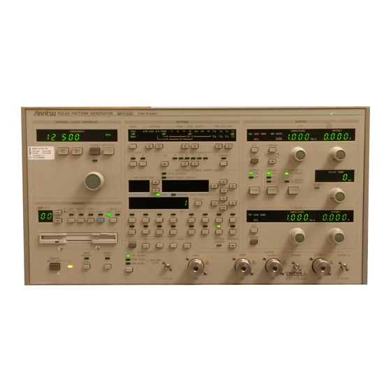
GENERAL 1.1 Features The MP1763C Pulse Pattern Generator has two data output channels (DATA and DATA) and three clock output channels (CLOCK1, CLOCK1, CLOCK2). The MP1763C is used with the MP1764A/C Error Detector to test high-speed digital communication systems and high-speed semiconductors. It operates over the 50 MHz to 12.5 GHz frequency range and generates four pulse patterns: alternate, programmable, zero substitution, and pseudorandom. -
Page 18: Specifications
Section 1 GENERAL 1.2 Specifications Internal Clock (OPTION 01) Operation frequency range External Clock Pattern Pattern length PRBS generation Mark ratio Number of “AND bit” shifts when setting mark ratio Zero substitution DATA DATA length Edit function Alternate pattern Output control A/B switching DATA length Edit function... - Page 19 Internal Pattern Error generation insertion External Gating input External Frequency range Clock Input Input level Input waveform Input impedance Connector Clock output Number of outputs Delay range CLOCK1 / CLOCK1 Amplitude Offset Rise/fall times (10%–90%) Waveform distortion Duty ratio adjust function Load impedance Termination...
- Page 20 Section 1 GENERAL DATA output Output waveform Number of outputs Amplitude Offset voltage DATA/DATA Tracking Rise / fall time Pattern jitter Waveform distortion Termination Load impedance Connector Output phase DATA DATA CLOCK1 CLOCK1 CLOCK2 CLOCK1/CLOCK1 delay set to 0 ps DATA, DATA 2 systems independence 0.25 to 2.0 Vp-p/Step 2 mV Setting error: ±15 % or ±100 mV, whichever is larger...
- Page 21 1/8 output Number of output Data polarity Output level Rise / fall time Pattern jitter Waveform distortion Skew Output bit rate Load impedance Connector Sync. output Output level Load impedance Connector Alternate pattern A/B switching input Minimum pulse width Input level Input impedance Connector Alternate pattern...
- Page 22 Section 1 GENERAL Error Disable input Input level Input impedance Connector External Gating input Minimum pulse width Input level Input impedance Connector Medium Parameter memory Format Stored data Mode switching Display Display switching Panel lock External control GPIB interface for one system GPIB connector for external control GPIB Initialization...
- Page 23 Option-01 Name Frequency range Output level Resolution Frequency accuracy Reference signal Signal purity Spurious radiation Load impedance Connector Option-03 Name Number of output Output bit rate Data polarity Termination Amplitude Offset voltage Rise/fall time Pattern jitter Waveform distortion Skew Output impedance Connector * When OPTION 03 is installed, there is no 1/8 output.
-
Page 24: Composition
Section 1 GENERAL 1.3 Composition The standard composition of the MP1763C Pulse Pattern Generator is shown in Table 1.3-1. Table 1.3-1 MP1763C Standard Composition Item Main Unit MP1763C Pulse Pattern Generator Options MP1763C-01 Internal synthesizer MP1763C-03 1/4 speed output Accessories J0500A... -
Page 25: Section 2 Preparations
2.1 Environmental Conditions of Installation Site Do not use and store the instrument in the following locations: • where vibrations are severe. • where it is damp or dusty. • where there is exposure to direct sunlight. • where there is exposure to active gases. Long-term storage at high temperatures will shorten the life of the internal battery. -
Page 26: Connecting The Power Cord
Section 2 PREPARATIONS 2.3 Power Connection This section describes the procedures for supplying power. 2.3.1 Power Requirements For normal operation of the instrument, observe the power voltage range described below. Voltage range 85 to 132 V 170 to 264 V Changeover between 100 and 200 V systems is made automatically. -
Page 27: Damage Prevention Measures
To protect this instrument against electrostatic damage, place a conductive mat on the work bench, and wear a wrist strap. Connect the other end of the wrist strap to the conductive mat, or the GND terminal of this instrument. MP1763C Earth wire... - Page 28 Section 2 PREPARATIONS...
-
Page 29: Section 3 Description Of Panels And Connectors
SECTION 3 DESCRIPTION OF PANELS AND CONNECTORS... - Page 30 PULSE PATTERN GENERATOR MP1763C INTERNAL CLOCK (OPTION.01) LOGIC PATTERN ALTNDATA Z.S PRBS FREQUENCY TUNING RESOLUTION ALTN A / B LOOP TIME MEMORY EXIST MODE RECALL SAVE FILE No. DELETE RESAVE SHIFT PATT OTHERS GUARD SYNC OUTPUT GPIB PANEL REMOTE LOCK...
- Page 32 ERROR GPIB FUNCTION INTERNAL BUFFER ADDITION CH ADDRESS SYNTHESIZER SYSTEM OUTPUT ( 1 - 32 ) OUTPUT CONTROL 5 4 3 2 1 8 7 6 5 4 3 2 1 50Ω GPIB ×10 ×1 CLOCK S111 A111 INPUT S R 1 R L 1 P P 0 D C 1 D T 1 50Ω...
- Page 34 Section 3 DESCRIPTION OF PANELS AND CONNECTORS...
-
Page 35: Section 4 Operating Instructions
4.1 Internal Clock Generator Frequency Setting (OPTION 01) This section sets the frequency of the internal clock generator when the CLOCK generator (OPTION 01) is used. TUNING ON/OFF RESOLUTION SECTION 4 OPERATING INSTRUCTIONS INTERNAL CLOCK (OPTION.01) FREQUENCY TUNING The frequency can be changed only when the TUNING LAMP is lit. Used when setting the frequency down to the kHz order. - Page 36 Section 4 OPERATING INSTRUCTIONS ③ INTERNAL CLOCK (OPTION.01) FREQUENCY TUNING Note: The frequency may not be stable just after the power is turned on. Make a warm-up run for 10 minutes or longer before use. Life time of coaxial switches: This equipment uses built-in coaxial switches, whose average life time is as follows.
-
Page 37: Generation Pattern Setting
4.2 Generation Pattern Setting LOGIC LOGIC PATTERN PRBS/ZERO SUB Mark ratio Alternate Number of alternate loops DATA length/continuous 0 bits length PAGE/pattern sync position Bit setting Bit setting (special) Bit setting (special) Error addition ON/OFF Error addition rate selection Single error addition Tracking ON/OFF Display switching PATTERN... -
Page 38: Alternate Pattern Setting
Section 4 OPERATING INSTRUCTIONS 4.2.1 Logic modification PATTERN LOGIC PATTERN PRBS / ZERO SUBST ALTNDATA Z.S PRBS 2 - 1 ① 4.2.2 Alternate pattern setting ① PATTERN LOGIC PATTERN PRBS / ZERO SUBST ALTNDATA Z.S PRBS 7 2 - 1 ALTN ERROR ADDITION(1×10 ②... - Page 39 PRESET PAGE GUARD Two patterns, A and B, can be set, and repetition times can be set for each pattern. The data lengths are the same for both patterns. The following are examples of 128bit patterns: Pattern A: 0 0 0 ••• 1 1 1 Repetition time: 2 Pattern B: 1 0 1 •••...
-
Page 40: Data Pattern Setting
Section 4 OPERATING INSTRUCTIONS 4.2.3 DATA pattern setting PATTERN LOGIC PATTERN PRBS / ZERO SUBST ALTNDATA Z.S PRBS 7 2 - 1 ① DATA LENGTH/ZERO SUBST DATA LENGTH A / B LOOP TIME ZERO SUBST LENGTH PAGE/ PATTERN SYNC POSITION DISPLAY DATA LENGTH/ZERO SUBST DATA LENGTH... -
Page 41: Zero Substitution
4.2.4 ZERO SUBSTITUTION PATTERN LOGIC PATTERN PRBS / ZERO SUBST ALTNDATA Z.S PRBS 7 2 - 1 ① PATTERN LOGIC PATTERN PRBS / ZERO SUBST ALTNDATA Z.S PRBS 7 2 - 1 ② DATA LENGTH/ZERO SUBST DATA LENGTH A / B LOOP TIME ZERO SUBST LENGTH PAGE/ PATTERN SYNC POSITION... -
Page 42: Pseudo Random Pattern Setting
Section 4 OPERATING INSTRUCTIONS 4.2.5 Pseudo random pattern setting PATTERN LOGIC PATTERN PRBS / ZERO SUBST ALTNDATA Z.S PRBS 7 2 - 1 ① PATTERN LOGIC PATTERN PRBS / ZERO SUBST ALTNDATA Z.S PRBS 7 2 - 1 ② Patterns generated as explained in Section 5.1 “ Pseudo random patern”. When an optional continuous N-bit pattern is selected in a PRBS pattern having a 2 except all-1s are provided. -
Page 43: Error Addition
4.2.6 ERROR addition ERROR ADDITION(1×10 ① ② ERROR ADDITION(1×10 Error addition can be inserted for one, and only one, of the 32 routes by using the rotary switch on the rear panel (see below). Therefore, the error multiplied by the output can be added to only one route of the output (1/8 OUTPUT ). Example) When a 1 x 10 error is added to one channel, following occurs:... -
Page 44: Tracking
4-10 ① When the key is pressed, the LED inside the key lights and the instrument enters the tracking mode. * When tracking, the MP1763C must be connected to an PATTERN TRACKING LOADING MP1764A/C by a GPIB. -
Page 45: Pattern Sync. Position
4.2.8 Pattern SYNC. position SYNC OUTPUT 1 / 64 CLOCK FIXED POSN PATTERN VAR POSN SYNC 1/64 CLOCK, FIXED POSITION, OR VARIABLE POSITION can be selected. 1/64 CLOCK: 1/1 CLOCK is divided by 64. FIXED POSITION: The sync pulse output fixed on page 1 of VARIABLE POSITION is generated. VARIABLE POSITION: The sync pulse position is shifted by 16 bits every time the PATTERN SYNC POSITION value is changed by one. - Page 46 Section 4 OPERATING INSTRUCTIONS When the PRBS DATA output is monitored on a sampling oscilloscope using each synchronization output, the following waveforms are shown: 1) 1/64 CLOCK Shown as an eye pattern. 2) FIXED POSN Shown as a 0 and 1 waveform. and VAR POSN *...
-
Page 47: Output Interface
4.3 Output Interface 50Ω GND GUARD OUTPUT 50Ω GND GUARD Termination conditions setting (DATA side) DATA/DATA displaying switching and DATA/DATA tracking Amplitude (DATA side) Offset (DATA side) Output ON/OFF Offset display standard setting 1/1 SPEED / 1/4 SPEED display switching CLOCK delay Termination conditions setting (CLOCK 1 side) Amplitude (CLOCK 1 side) -
Page 48: Dummy Terminal Voltage Switching
Section 4 OPERATING INSTRUCTIONS 4.3.1 DUMMY terminal voltage switching ① OUTPUT DATA AMPLITUDE 50Ω GND DATA DATA Vp - p DISPLAY DATA/DATA GUARD TRACKING OUTPUT OFFSET DISPLAY 1/1 SPEED 1/4 SPEED (OPTION.03) CLOCK 1 AMPLITUDE 50Ω GND Vp - p GUARD ②... -
Page 49: Amplitude, Offset, And Delay Setting
4.3.2 Amplitude, offset, and delay setting ② ③ OUTPUT DATA AMPLITUDE 50Ω GND DATA DATA Vp - p DISPLAY DATA/DATA GUARD TRACKING OUTPUT OFFSET DISPLAY 1/1 SPEED 1/4 SPEED (OPTION.03) BUSY ① ④ ⑥ ① When you want to set front panel DATA/DATA output and CLOCK 1/CLOCK 1 output, switch to 1/1 SPEED. - Page 50 Section 4 OPERATING INSTRUCTIONS OUTPUT DATA AMPLITUDE 50Ω GND DATA DATA Vp - p DISPLAY DATA/DATA GUARD TRACKING OUTPUT OFFSET DISPLAY 1/1 SPEED 1/4 SPEED (OPTION.03) OUTPUT DATA AMPLITUDE 50Ω GND DATA DATA Vp - p DISPLAY DATA/DATA GUARD TRACKING OUTPUT OFFSET DISPLAY...
-
Page 51: Cross Point Adjustment
Life time of phase shifters: This equipment uses built-in phase shifters, whose average life time is as fol- lows. Number of shifting times at -500 ps to +500 ps full scale: 100 thousands times 4.3.3 Duty adjustment Fine adjustment of the CLOCK1/CLOCK1 duty can be done using the control on the side of the instrument. The duty depends on the frequency, If the frequency is changed, monitor the waveform by sampling etc. -
Page 52: Offset Voltage Setting Range
Section 4 OPERATING INSTRUCTIONS 4.3.5 Offset voltage setting range (Large amplitude) Fig. 4.3.5-1 Offset Reference Value and Amplitude Change Note: Since the offset-voltage upper and lower limit values are limited by V or V are set, the amplitude is limited at a certain value and may not change further. Example: If V is set at +1.00 V offset voltage and if there is a signal with amplitude 0.5 Vp-p added, that amplitude can only be increased to 1.0 Vp-p. - Page 53 -3.0 -2.0 -4.0 Fig. 4.3.5-2 Amplitude and Offset Voltage Setting Range Corresponding to Offset Reference Value 0.25 0 1.0 2.0 3.0 -1.0 • Offset reference: V OFFSET (V) 4-19...
- Page 54 Section 4 OPERATING INSTRUCTIONS -2.125 -4.0 -3.0 Fig. 4.3.5-3 Amplitude and Offset Voltage Setting Range Corresponding to Offset Reference Value 4-20 0.25 -2.0 -1.0 1.0 2.0 3.0 • Offset reference: V 1.875 OFFSET (V)
- Page 55 4.3 Output Interface • Offset reference: V 0.25 1.75 -2.25 -4.0 -3.0 -2.0 -1.0 0 1.0 2.0 3.0 OFFSET (V) Fig. 4.3.5-4 Amplitude and Offset Voltage Setting Range Corresponding to Offset Reference Value 4-21...
-
Page 56: Memory (Floppy Disk)
Section 4 OPERATING INSTRUCTIONS 4.4 MEMORY (Floppy Disk) File No. selection File control Mode selection Eject 4-22 MEMORY EXIST RECALL SAVE FILE No. DELETE RESAVE SHIFT PATT OTHERS MODE... -
Page 57: File Save
4.4.1 File save ④ ③ MEMORY EXIST RECALL FILE No. DELETE RESAVE SHIFT PATT OTHERS ① ① Insert a formatted floppy disk (2HD, 2DD) into the floppy ② disk drive. (For a description of how to format a floppy disk, see section 4.4.3 “Disk formatting”.) MODE SAVE ②... -
Page 58: Disk Formatting
Section 4 OPERATING INSTRUCTIONS 4.4.2 File recall ① ③ ② MEMORY EXIST RECALL FILE No. DELETE 4.4.3 Disk formatting ①④ ③ MEMORY EXIST RECALL FILE No. DELETE 4-24 ① Insert the floppy disk into the floppy disk drive and select the DIR mode. -
Page 59: Error Messages
4.4.4 File deletion ①⑤ ④ ③ MEMORY EXIST RECALL SAVE FILE No. DELETE RESAVE SHIFT PATT OTHERS 4.4.5 Error messages When a floppy disk error occurs, error codes E0 to E9 are displayed on the file name display. For the error codes, see Table 4.4.5-1 “Error Messages”. -
Page 60: Floppy Disk Precautions
Compatiblity It is possible for MP1763C PPG to use ' PTN ' file mode by MP1764A/C ED. ' OTH ' file is not used. It is impossible for MP1763C to read file made by old type PPG, for example MP1701B, MP1608A and MP1652A. -
Page 61: Parameters Initialization
4.5 Parameters initialization When returning the pattern type, amplitude, offset voltage, and other parameters to the factory shipment state, turn on the power switch while pressing the LOCAL key. This initializes the parameters. The initialization state is shown in Table 4.5-1. Item FREQUENCY TUNING... -
Page 62: Functions Of The Function Switch
Section 4 OPERATING INSTRUCTIONS 4.6 Functions of the FUNCTION Switch Table 4.6-1 lists the functions of the FUNCTION switch on the rear of the instrument. Table 4.6-1 Functions of the FUNCTION Switch AND bit shift count for the mark ratio External error injection Floppy disk format type Alternate pattern A/B switching timing... -
Page 63: Section 5 Principles Of Operation
5.1 Pseudorandom Pattern (PRBS Pattern) The principle of pseudorandom pattern generation is shown in Table 5.1-1. The pseudorandom pattern is represented by the Nth-order generation polynomial shown in Table 5.1-1. One period is 2 produces one N bits continuous “1” pattern per period. When LOGIC is set to POS (positive logic), PRBS pattern output level “1”... - Page 64 Section 5 PRINCIPLES OF OPERATION PRBS pattern generator (See Table 5.1-1) Fig. 5.1-1 Mark Ratio 1/4, 1/8 Pattern Generator DATA1 DATA2 DATA3 DATA4 DATA5 DATA6 2 /8 bits leading DATA7 2 /8 bits leading DATA8 For example, when PRBS 2 -1, 2 /8=4096 bits. Shift register 2 /8 bits leading...
-
Page 65: Pattern Synchronized Output Period
5.2 Pattern Synchronized Output Period 5.2.1 Pseudorandom pattern 1 × (2 Period = (set frequency) N=7, 9, 11, 15, 20, 23, 31 (Where pulse width = 5.2.2 Programmable pattern Data pattern, alternate pattern (a) Data length = 65536 or less 1 Period = (set frequency) -
Page 66: Bit Shift For Alternate A/B Select Timing
Section 5 PRINCIPLES OF OPERATION 5.3 Bit shift for Alternate A/B select timing A timing between Alternate pattern A/B select signal and Data output can be selected using the Dip switch on the rear of the instrument, and its selection step is one 128th of setting frequency. Data Output 0 bit shift 1 bit shift... -
Page 67: Section 6 Performance Test
(MARJ RATIO 1/8 to 7/8) START EXIST POWER INTERNAL CLOCK (OPTION.01) EXIST POWER Wave form monitor setup PULSE PATTERN GENERATOR MP1763C 0.05 - 12.5GHz INTERNAL CLOCK (OPTION.01) PATTERN LOGIC PATTERN PRBS / ZERO SUBST PRBS MARK RATIO ALTNDATA Z.S PRBS... -
Page 68: Test Method
REMOTE LOCK POWER LOCAL Set the Error Detector to the same conditions as the MP1763C or set the margin to maximum. Confirm that the following points are Error Free: Frequency 50 MHz, 1 GHz, 3 GHz, 5 GHz, 12.5 GHz Amplitude 0.25 Vp-p, 2.0 Vp-p... -
Page 69: Waveform Check
S111 A111 S R 1 R L 1 P P 0 D C 1 D T 1 6.4 Waveform Check Connect the MP1763C and sampling oscilloscope in accordance with 6.2-(2). Check the DATA, DATA, CLOCK, and CLOCK1 waveforms. Pattern LOGIC... - Page 70 Section 6 PERFORMANCE TEST...
-
Page 71: Section 7 Maintenance
7.1 Daily Maintenance • Wipe external dirt with a cloth soaked in a diluted neutral detergent. • Remove dust or specks by using a vacuum cleaner. • Periodically clean the FDD head by using a 3.5-inch head-cleaning disk. • If any loosened screws for attached parts are found, secure by using the specified tool. 7.2 Storage Precautions (1) Store the unit after removing any dirt or dust. -
Page 72: Calibration
Section 7 MAINTENANCE 7.4 Calibration Calibration of this unit should not be performed by other than Anritsu Corporation. We recommend yearly routine calibra- tion to maintain performance. 7.5 Disposal This equipment uses chemical compound semiconductors including arsenic and a fluoridated graphite lithium battery to... -
Page 73: Section 8 Troubleshooting And Repair
TROUBLESHOOTING AND REPAIR 8.1 Before Considering Trouble If the instrument is not operating properly for some reason, check it as follows: • Power is not turned on Is the power cord loose ? ↓ Is the fuse blown ? • Synchronization is not established. -
Page 74: Fuse Replacement
↓ Is the head of floppy disk drive dusty ? If the problem cannot be found from the above check items, contact the service section of Anritsu. 8.2 Fuse Replacement Turn off the power switch, then disconnect the power cable plugged into the AC power inlet. Next, open the AC power fuse holder cover and replace the fuse with a spare. -
Page 75: Appendix A Performance Test Report Sheet
PERFORMANCE TEST REPORT SHEET Name : MP1763C Pulse Pattern Generator Serial No. Ambient Temperature Relative humidity • Output Test Conditions For Data and Clock1 50 MHz Error-free for each: Amplitude: 0.25, 2.0 Vp-p Offset: –2, 0, +2 V Mark ratio: 1/2, 1/8, 1/2 and 7/8... - Page 76 APPENDIX A PERFORMANCE TEST REPORT SHEET ..
-
Page 77: Index
INDEX Cross point adjust ----------------------------------- 4-17 Duty adjust ------------------------------------------- 4-17 Tracking ---------------------------------------------- 4-10 Error insertion --------------------------------------- 4-9 Alternate pattern ------------------------------------ 4-4 Pseudo random pattern ---------------------------- 5-1 Zero-replacing pattern ----------------------------- 4-7 Data pattern ------------------------------------------ 4-6 Pattern synchronization output ------------------ 4-11 INDEX-1... - Page 78 INDEX ..INDEX-2...
Need help?
Do you have a question about the MP1763C and is the answer not in the manual?
Questions and answers