Anritsu MP1800A Installation Manual
Signal quality analyzer
Hide thumbs
Also See for MP1800A:
- Operation manual (272 pages) ,
- Quick reference (38 pages) ,
- Quick start manual (11 pages)
Table of Contents
Advertisement
Quick Links
Advertisement
Table of Contents

Related Manuals for Anritsu MP1800A


Summary of Contents for Anritsu MP1800A
- Page 1 MP1800A Signal Quality Analyzer Installation Guide 18th Edition For safety and warning information, please read this manual before attempting to use the equipment. Keep this manual with the equipment. ANRITSU CORPORATION Document No.: M-W2747AE-18.0...
- Page 2 Ensure that you clearly understand the meanings of the symbols BEFORE using the equipment. Some or all of the following symbols may be used on all Anritsu equipment. In addition, there may be other labels attached to products that are not shown in the diagrams in this manual.
-
Page 3: For Safety
For Safety WARNING • ALWAYS refer to the operation manual when working near locations at which the alert mark shown on the left is attached. If the advice in the operation manual is not followed, there is a risk of personal injury or reduced equipment performance. - Page 4 • The performance-guarantee seal verifies the integrity of the equipment. Calibration To ensure the continued integrity of the equipment, only Anritsu service personnel, or service personnel of an Anritsu sales representative, should break this seal to repair or calibrate the equipment.
- Page 5 For Safety CAUTION • Always remove the main power cable from the power outlet before Cleaning cleaning dust around the power supply and fan. Clean the power inlet regularly. If dust accumulates around the power pins, there is a risk of fire. Keep the cooling fan clean so that the ventilation holes are not obstructed.
- Page 6 For Safety Class 1 indicates the danger degree of the laser radiation specified below according to IEC 60825-1:2007. Class 1: Lasers that are safe under reasonably foreseeable conditions of operation, including the use of optical instruments for intrabeam viewing. CAUTION Use of controls or adjustments or performance of procedures other than those specified herein may result in hazardous radiation exposure.
- Page 7 For Safety The laser in this equipment is classified as Class 1 according to the IEC Laser Safety 60825-1:2007 standard. Table 1 Laser Safety Classifications Based on IEC 60825-1:2007 G0174A Fig. 2, 0.78 840-860 36.9 850 nm XFP module G0175A Fig.
- Page 8 For Safety Table 2 Incorporated Laser Specification G0174A 0.78 840-860 36.9 850 nm XFP module G0175A MU181600A 1290-1330 11.5 1310 nm XFP module G0176A 1.58 1530-1565 11.5 1550 nm XFP module G0177A 0.56 830-860 36.9 850 nm SFP module G0178A MU181601A 1270-1360 11.5...
- Page 9 For Safety Table3 Labels on Product Affixed Type Label Model Name Explanation Fig. 1, A MP1800A Certification Fig. 1, B MP1800A Identification Fig. 1, C MP1800A Fig. 2, A MU181600A Explanation MU181601A Fig. 3, A Explanation Fig. 4, A MU181620A...
- Page 10 For Safety Laser Radiation Markings Figure 1 MP1800A Exterior...
- Page 11 For Safety Laser Radiation Markings Figure 2 Front Panel of MU181600A Module Figure 3 Front Panel of MU181601A Module Figure 4 Front Panel of MU181620A Module...
- Page 12 Back-up Battery backup the memory. This battery must be replaced by service personnel when it has reached the end of its useful life; contact the Anritsu sales section or your nearest representative. Note: The battery used in this equipment has a maximum useful life of 7 years.
- Page 13 Anritsu will not be held responsible for lost data. • The equipment should only be used within the recommend temperature range, and should not be used in locations where the temperature may fluctuate suddenly.
- Page 14 In addition, this warranty is valid only for the original equipment purchaser. It is not transferable if the equipment is resold. Anritsu Corporation shall assume no liability for damage or financial loss of the customer due to the use of or a failure to use this equipment, unless the damage or loss is caused due to Anritsu Corporation’s intentional or gross...
- Page 15 Anritsu Corporation Contact In the event of this equipment malfunctions, please contact an Anritsu Service and Sales office. Contact information can be found on the last page of the printed version of this manual, and is available in a separate file on the...
- Page 16 Notes On Export Management This product and its manuals may require an Export License/Approval by the Government of the product's country of origin for re-export from your country. Before re-exporting the product or manuals, please contact us to confirm whether they are export-controlled items or not. When you dispose of export-controlled items, the products/manuals need to be broken/shredded so as not to be unlawfully used for military purpose.
- Page 17 Anritsu electronic equipment, etc.). By using this Software, you shall be deemed to have agreed to be bound by the terms of this EULA, and Anritsu Corporation (hereafter Anritsu) hereby grants you the right to use this Software with the Anritsu specified equipment (hereafter Equipment) for the purposes set out in this EULA.
- Page 18 Software with members of such organization. except as authorized by the laws and 2. You and Anritsu may terminate this EULA regulations of Japan and the United States, by a written notice to the other party 30 etc.
- Page 19 Cautions Against Computer Virus Infection • Copying files and data Only files that have been provided directly from Anritsu or generated using Anritsu equipment should be copied to the instrument. All other required files should be transferred by means of USB flash drive or CompactFlash media after undergoing a thorough virus check.
- Page 20 2012/19/EU (the “WEEE Directive”) in European Union. For Products placed on the EU market after August 13, 2005, please contact your local Anritsu representative at the end of the product's useful life to arrange disposal in accordance with your initial contract and the local law.
- Page 21 CE Conformity Marking Anritsu affixes the CE conformity marking on the following product(s) in accordance with the Decision 768/2008/EC to indicate that they conform to the EMC, LVD, and RoHS directive of the European Union (EU). CE marking 1. Product Model...
- Page 22 as intended. B: The equipment shall continue to operate as intended after the test. No degradation of performance or loss of function is allowed below a performance level specified by the manufacturer, when the equipment is used as intended. The performance level may be replaced by a permissible loss of performance.
- Page 23 4. Contact Name: Anritsu GmbH Address, city: Nemetschek Haus, Konrad-Zuse-Platz 1 81829 München, Country: Germany Name: ANRITSU EMEA Ltd. Address, city: 200 Capability Green, Luton Bedfordshire, LU1 3LU Country: United Kingdom xxiii...
- Page 24 RCM Conformity Marking Anritsu affixes the RCM mark on the following product(s) in accordance with the regulation to indicate that they conform to the EMC framework of Australia/New Zealand. RCM marking 1. Product Model Model: MP1800A Signal Quality Analyzer 2. Applied Standards...
- Page 25 About Eco label The label shown on the left is attached to Anritsu products meeting our environmental standards. Details about this label and the environmental standards are available on the Anritsu website at https://www.anritsu.com...
- Page 26 xxvi...
-
Page 27: About This Manual
About This Manual A testing system combining an MP1800A Signal Quality Analyzer or MT1810A 4 Slot Chassis mainframe, module(s), and control software is called the Signal Quality Analyzer Series. The operation manuals of the Signal Quality Analyzer Series consist of separate documents for the installation guide, the mainframe, remote control operation, module(s), and control software, as shown below. - Page 28 This document provides usage of the MP1800A for the first time, as well as module composition change, remote control or software update procedures. • Read all the sections in this document when using the MP1800A for the first time. • To change module composition, refer to Section 2.3 “Installing and Removing Modules.”...
-
Page 29: Table Of Contents
Table of Contents For Safety ............ About This Manual........Chapter 1 Overview ........... 1-1 Product Overview ............1-2 Product Composition ............ 1-3 Chapter 2 Preparation before Use ....2-1 Environmental Conditions of Installation Site ....2-2 Distance from Fan ............2-3 Installing and Removing Modules ......... - Page 30 Chapter 5 Other Functions ....... 5-1 Checking Installed Software Version ......5-2 Updating Software ............5-6 Initializing Settings ............5-8 Adding Options ............. 5-9 Deleting Files .............. 5-11 Chapter 6 Installing MX180000A ...... 6-1 Installing MX180000A ........... 6-2 Installing USB Driver ............. 6-7 Chapter 7 Self-Test ...........
-
Page 31: Chapter 1 Overview
Chapter 1 Overview This chapter provides an overview of the MP1800A Signal Quality Analyzer (hereinafter, referred to as “MP1800A”). Product Overview ............1-2 Product Composition ............ 1-3 1.2.1 Mainframe ............1-3 1.2.2 Module .............. 1-5 1.2.3 Restrictions on operations when multiple modules are mounted ........ -
Page 32: Product Overview
Channel Synchronization functions to perform pattern generation sync and receive sync between each module. In addition, the MP1800A is equipped with LCDs, keys and a rotary encoder for easy operation. Remote control can also be performed by adding the GPIB or LAN options. -
Page 33: Product Composition
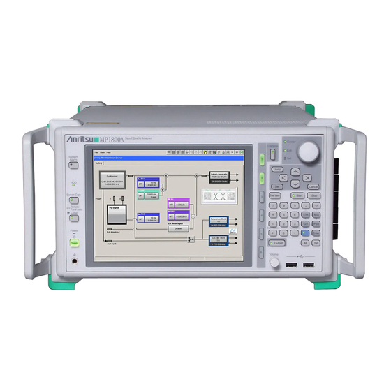
The MP1800A can operate alone, without an external control PC. Figure 1.2.1-1 MP1800A appearance The standard composition of the MP1800A is shown in the table below. See the MP1800A Signal Quality Analyzer Operation Manual for options, application parts, and specifications. - Page 34 Chapter 1 Overview Module insertion slots The MP1800A is equipped with slots for installing up to 6 modules into the side panel. Figure 1.2.1-2 MP1800A side panel When installing the MU181020A, MU181020B, MU181040A, and/or MU181040B, the installation position and installed number of boards vary according to the options being added.
-
Page 35: Module
MU181040B, the installation position and installed number of boards vary according to the options being added. See the release notes attached to the MP1800A for details on the possible location and quantity of modules that can be installed for operation. -
Page 36: Restrictions On Operations When Multiple Modules Are Mounted
Restrictions on Independent function operations • When two or more MU181020A/B and/or MU181040A/B modules are mounted on the MP1800A unit, two frequency bands of 0.1 to 6 Gbit/s and 6 to 12.5 Gbit/s must not be mixed between MU181020A/B modules and between MU181040A/B modules. - Page 37 Product Composition MP1800A-016 with four MU181020A and two MU181040A modules mounted Example: Master module of MU181020A modules MP1800A-016 Slot1 MU181020A • Operate in the same frequency band. Slot2 MU181020A • Input a clock signal to the master module Slot3 MU181020A inserted into Slot1.
-
Page 38: Software
Figure 1.2.3-3 Example restrictions in c When mounting MU181020A/B or MU181040A/B modules onto the MP1800A, the installation position and installed number of boards vary according to the options being added. For details, refer to the release note included in this equipment or refer to the Anritsu homepage (http://www.anritsu.com). - Page 39 Chapter 2 Preparation before Use This chapter describes preparations required before starting measurements with the MP1800A. Environmental Conditions of Installation Site ....2-2 Distance from Fan ............2-3 Installing and Removing Modules ......... 2-4 2.3.1 Installing modules ..........2-4 2.3.2 Removing modules ........... 2-7 Power Connection ............
-
Page 40: Chapter 2 Preparation Before Use
Substantial temperature changes Note: Dew may form inside of the MP1800A if it is moved to a warm location after operating for a long time in a cool location. In such a case, be sure to wait until the MP1800A becomes completely dry before turning on the power switch. -
Page 41: Distance From Fan
Distance from Fan 2.2 Distance from Fan A cooling fan is provided at the rear of the MP1800A. Install the MP1800A at least 10 cm away from walls, peripheral devices, or the like to prevent blockage of ventilation. Insufficient ventilation may cause the internal temperature to rise, resulting in failure. -
Page 42: Installing And Removing Modules
Chapter 2 Preparation before Use 2.3 Installing and Removing Modules Slots for the modules are numbered 1 to 6, from the top. Figure 2.3-1 MP1800A and modules 2.3.1 Installing modules Disconnect the power cord. Fully insert a module, sliding along the grooves. - Page 43 Screws Figure 2.3.1-2 Modules screws CAUTION Be sure to check that the power cord of the MP1800A is disconnected before installing the modules. Installing modules with the power cord connected may result in failure. ...
- Page 44 Chapter 2 Preparation before Use CAUTION Insert the modules such that they are parallel to the grooves, without tilting them (see the figure below). Failure to do so may deform the metal spring on top of the modules. Insertion direction Groove Correct: plug-in module parallel with grooves Incorrect: plug-in module not parallel with grooves...
-
Page 45: Removing Modules
Installing and Removing Modules 2.3.2 Removing modules Disconnect the power cord. Loosen the left and right screws on the module to be removed. Screws Figure 2.3.2-1 Modules screws Press the red ejector lock buttons on both sides of the module to unlock the ejector. - Page 46 Chapter 2 Preparation before Use CAUTION Be sure to check that the power cord of the MP1800A is disconnected before pulling out the modules. Pulling out modules with the power cord connected may result in failure. Take countermeasures against static electricity (ESD) when pulling out modules.
-
Page 47: Power Connection
Insert the power plug into an outlet, and connect the other end to the power inlet on the rear panel. To ensure that the MP1800A is earthed, always use the supplied 3-pin power cord, and insert the plug into an outlet with an earth terminal. - Page 48 If the MP1800A is mounted in a rack, a power switch for the rack or a circuit breaker may be used for power disconnection.
-
Page 49: Measures Against Eos And Esd
(EOS) or electrostatic discharge (ESD). 2.5.1 How to use the GND connection cable There is a risk of damaging MP1800A due to EOS if MP1800A and other peripheral equipment (including experimental circuits) are not connected to the common ground. -
Page 50: How To Use The Esd Discharger
Chapter 2 Preparation before Use 2.5.2 How to use the ESD Discharger There is a risk of damaging MP1800A if the coaxial cable you connect to MP1800A is charged electrostatically. To prevent MP1800A from being damaged by ESD, remove electrostatic charges from the cable by using the ESD Discharger before cabling the connectors. -
Page 51: Connecting With Peripheral Devices
2 ports Figure 2.6-1 USB interfaces The MP1800A has USB interface ports (Revision 1.1), two ports on the front panel and one port on the rear panel as standard. Use the USB ports to connect the USB mouse or a keyboard. - Page 52 LCD of the MP1800A can be performed. GPIB Connect a cable to the GPIB connector on the rear of the MP1800A before turning on the MP1800A. Connecting after the MP1800A has been turned on may cause failure. Refer to Section 4.3 “Using GPIB”...
-
Page 53: Connecting To Network
Connecting to Network 2.7 Connecting to Network When connecting the MP1800A to a network, be sure to set the IP address using the setup utility, so as not to conflict with the IP address of any other device on the network. Consult your network administrator for available IP address. - Page 54 Chapter 2 Preparation before Use 2-16.
-
Page 55: Chapter 3 Start/Stop Procedures
Chapter 3 Start/Stop Procedures This chapter describes the start and stop procedures of the application software for using the MP1800A. Start Procedure ............. 3-2 Stop Procedure ............. 3-4... -
Page 56: Start Procedure
Chapter 3 Start/Stop Procedures 3.1 Start Procedure At non-standby status (when Standby LED is off) Connect the power cord to turn on the MP1800A. The Power lamp turns on. The selector screen opens automatically after startup of Windows. Standby LED Inlet Figure 3.1-1 Front and rear panels... - Page 57 Do not power off the MP1800A during downloading, or the MP1800A may be damaged Self test Starts a self-test.
-
Page 58: Stop Procedure
Click the [Shut down] button on the selector screen. The Power lamp goes off, and then the Standby LED lights up (enters the standby status). CAUTION The MP1800A has an internal hard disk drive. Do not remove the power cord during startup of the MP1800A, except for an emergency. 3-4. -
Page 59: Chapter 4 Remote Control
Chapter 4 Remote Control Remote control of the MP1800A can be performed via Ethernet or GPIB interface. This chapter describes the remote control procedure. Selecting Remote Interface .......... 4-2 Using Ethernet .............. 4-5 Using GPIB ..............4-7 Exiting Remote Control ..........4-8... -
Page 60: Selecting Remote Interface
[User] and click [OK] button. Figure 4.1-2 Setup Utility Login screen Click the [Remote Control] tab to open the remote control setting screen, select the remote interface used for the MP1800A, and set the operating environment for each interface. Note: When a remote control option (MP1800A-x01 and MP1800A-x02) is not installed, settings on the screen cannot be performed. - Page 61 Select [GPIB], [Ethernet] or [None] if no remote interface is used. GPIB Address Set the [GPIB] device address of the MP1800A used when GPIB is selected for the active interface. Windows Set the IP address, subnet mask, gateway address, and...
- Page 62 Chapter 4 Remote Control Refer to the MX180000A Signal Quality Analyzer Control Software Remote Control Operation Manual for details on remote control. Table 4.1-2 Remote interface Interface Setting item Initial value Active Interface None GPIB GPIB Address (Device) Active Interface None Ethernet Port Number...
-
Page 63: Using Ethernet
Select [Ethernet] referring to Section 4.1 Selecting Remote Interface, and set IP address, subnet mask, and gateway address for the MP1800A. The controller must be connected to the MP1800A with the IP address and ports displayed here. Figure 4.2-1 IP address check For details about the setting restrictions, refer to “MX180000A Signal... - Page 64 Chapter 4 Remote Control Twisted pair cable Figure 4.2-2 Ethernet cable connection...
-
Page 65: Using Gpib
Interface” to use a GPIB. A connector for the GPIB cable is provided on the rear panel. Be sure to connect the GPIB cable before turning on the MP1800A. Up to 15 devices, including the controller, can be connected in one GPIB system. Note that the cable length is limited, as shown below. -
Page 66: Exiting Remote Control
(2) Click [Shut down] on the selector screen. The power lamp goes off, Standby LED will lit (Changing to Standby status). CAUTION Do not pull out the power code when booting MP1800A except emargency stiuation because the MP1800A has built-in HDD. -
Page 67: Chapter 5 Other Functions
Chapter 5 Other Functions This chapter describes the procedure for checking software versions of the MP1800A and modules installed in it, and procedures for updating, setting initialization, and adding options later. Checking Installed Software Version ......5-2 Updating Software ............5-6 Initializing Settings ............ -
Page 68: Checking Installed Software Version
Chapter 5 Other Functions 5.1 Checking Installed Software Version The version of the software installed to the MP1800A can be checked by using [Help] on the menu bar of the main application or from the setup utility. Select [Help] – [Version] on the menu bar of the main application. The screen shown below displaying the currently installed software version opens. - Page 69 Clicking [Setup utility] opens the Setup Utility Login screen. Click [OK] in the status shown above. Figure 5.1-3 Setup Utility Login screen Click the [Version] tab to open the software version display screen. The software version and serial number of the MP1800A can be checked on this screen.
- Page 70 In this case, update the internal software by referring to Section 5.2 “Updating Software.” Using the MP1800A while the internal software versions mismatch may result in abnormal operation.
- Page 71 Checking Installed Software Version The setup utility version can also be checked by clicking the [Help] tab. Figure 5.1-5 Setup utility version display...
-
Page 72: Updating Software
Chapter 5 Other Functions 5.2 Updating Software Software of the MP1800A and each module can be updated from the setup utility screen. When a new version of the software is installed, a version mismatch may occur between the new-version software and the MP1800A internal software. - Page 73 Execute downloading. The file versions stored in the internal HDD by the MX180000A installer are compared with the file versions downloaded in the MP1800A and each module, and if they differ, downloading of files is executed. Shows slot number and file name for downloading.
-
Page 74: Initializing Settings
File menu. It can also be initialized to the factory settings, using the setup utility. Start the setup utility and click the [Help] tab. Figure 5.3-1 Initialization of settings Click [Execute] in the [Initialize] group box to initialize the MP1800A to the factory settings. Note:... -
Page 75: Adding Options
Adding Options 5.4 Adding Options After purchasing the MP1800A, its option can be added just by entering the option key. Inform Anritsu of your MP1800A serial number when purchasing an option. An “Option Key License Certificate” will be sent to you. Add an option by using the setup utility. Select [Setup utility] on the selector screen. - Page 76 Clicking [Cancel] closes this screen and returns to the Setup Utility Login screen. Notes: 1. The option key can only be used for the MP1800A, the serial number for which is shown in the “Option Key License Certificate.” 2. The option key provided in the “Option Key License Certificate”...
-
Page 77: Deleting Files
Deleting Files 5.5 Deleting Files Before disposing of MP1800A, erase all data created on drives C and D by operation of Windows. 5-11... - Page 78 Chapter 5 Other Functions 5-12.
-
Page 79: Chapter 6 Installing Mx180000A
Chapter 6 Installing MX180000A This chapter describes how to install the MX180000A Signal Quality Analyzer Control Software (hereinafter, referred to as “MX180000A”), when reinstalling or upgrading MX180000A is required. Installing MX180000A ........... 6-2 Installing USB Driver ............. 6-7... -
Page 80: Installing Mx180000A
CD-ROM supplied with the MX180000A: \Installer\MX180000A_VER_x_xx_xx.exe x_xx_xx above indicates the software version. Insert the USB memory into the MP1800A to copy the files to the internal HDD. Use a USB memory device with at least 512 MB of memory available. - Page 81 Installing MX180000A The MX180000A installer starts up and the MX180000A installation wizard window (MX180000A - InstallShield Wizard) is displayed. Click [Next]. A list of products is displayed for selecting the target to be controlled by MX180000A. Select MP1800A and click [Next].
- Page 82 [Next]. For the serial number, enter the 10-digit serial number of the MP1800A that is to be controlled by MX180000A. The error message shown below will be displayed if an incorrect serial number is entered and [Next] is clicked. Click [OK] to close...
- Page 83 Installing MX180000A When installation is ready (the following window is displayed), click [Install] to start installation. If MP1800A-x07 is installed, you will see the following warning. Click [Install this driver software anyway] to continue the installation.
- Page 84 10. The following window is displayed when the installation completes normally. Click [Finish] to end the installation procedure. 11. Be sure to check the software version of the MP1800A after installing MX180000A. If the firmware version is not the latest, necessary files must be downloaded.
-
Page 85: Installing Usb Driver
Installing USB Driver 6.2 Installing USB Driver When reinstalling or upgrading MX180000A is required, it is necessary to install the USB driver in the controller. When the general procedures are followed by the installer, the confirmation dialog is displayed. Click [Yes] to start installation. Figure 6.2-1 Confirmation Dialog of USB Driver Installation (1) Figure 6.2-2 is displayed when the installation is in progress. - Page 86 Chapter 6 Installing MX180000A If MP1800A-x07 is installed, you will see the confirmation message shown in Figure 6.2-3. Click [Install] to continue the installation. Figure 6.2-3 Confirmation Dialog of USB Driver Installation (3) Note The screens shown in Figure 6.2-2 and Figure 6.2-3 may not be displayed on the front page.
- Page 87 Installing USB Driver When initially connecting the USB device such as the MP1821A or MP1825B to the MP1800A after installing software, install the driver using the following procedures. Connect the MP1800A and USB device using an USB cable. The Found New Hardware Wizard screen is displayed to confirm windows update.
- Page 88 Chapter 6 Installing MX180000A Select [Install the software automatically] and click [Next]. Figure 6.2-6 Installing software The following screen is displayed when the hardware is found. Click [Continue Anyway] to continue the installation procedures. Figure 6.2-7 Installing hardware 6-10...
- Page 89 Double-click [Add/Remove Programs in the Control Panel. If MP1800A-x07 is installed, click [Programs and Features] in Control Panel. Select [Anritsu USB Device Driver] from the list and click [Remove] to start the uninstallation. If MP1800A-x07 is installed, select [Anritsu USB Device Driver], and then click [Change/Remove].
- Page 90 Chapter 6 Installing MX180000A 6-12.
-
Page 91: Chapter 7 Self-Test
Chapter 7 Self-Test The MP1800A has a self-test function to check if the installed modules operate normally. This chapter describes the self-test procedure. Self-Test ................ 7-2... -
Page 92: Self-Test
Chapter 7 Self-Test 7.1 Self-Test The MP1800A has a self-test function (self-test application). This function detects module abnormalities. Be sure to exit the main application software before starting the self-test application. Next, select [Self Test] on the selector screen to display the Self-test main screen. - Page 93 Self-Test Figure 7.1-1 Self-test main screen Table 7.1-1 Explanation of Self-test main screen Name Function Select Opens the selection screen for the module on which self-test is performed. Start Click to start the self-test. The [Start] button is disabled when no test module is selected.
- Page 94 Chapter 7 Self-Test When [Select] is clicked on the Self-test main screen, the Test Module Select screen shown below is displayed for selecting a self-test target module. In this screen, a combination of modules for which the self-test is executed can be automatically selected by clicking [Auto]. Clicking [OK] closes the Test Module Select screen.
- Page 95 Notes: 1. For the combination of modules and options available for self-testing, access to the “MP1800 Series Signal Quality” on your Web site (https://www.anritsu.com). Right-click the “MP1800 Series Signal Quality” and you can access to your area website. 2. Refer to the MX180000A Signal Quality Analyzer Control Software Operation Manual for details on the self-test.
- Page 96 Chapter 7 Self-Test The connection guides are displayed in the [Guide] tab window. Connect the modules, referring to these guides. When the modules are connected completely, click [Start] to start a self-test. Figure 7.1-3 Connection guides screen Table 7.1-3 Explanation of connection guides screen Type Function Slot No.
- Page 97 Self-Test CAUTION Modules may be damaged if they are connected without following Notes on the screen. Notes: 1. Handle connectors that are not used in a self-test properly, using processes such as termination and open following the description in each module’s operation manual. 2.
- Page 98 Chapter 7 Self-Test The [Result] tab window that displays the self-test results for the test modules is shown below. When the self-test is completed, the self-test results are displayed in the Result tab window. The item is left blank if a self-test is not executed for that item.
-
Page 99: Chapter 8 Troubleshooting
Chapter 8 Troubleshooting This chapter describes the procedures to check if a failure has occurred during abnormal operation of the MP1800A. Problems upon Power-on ..........8-2 Problems upon Module Replacement ......8-2 Software Problems ............8-3... -
Page 100: Problems Upon Power-On
Is the Standby LED is If the power cord is removed and inserted during turned on? startup of the MP1800A, the MP1800A may not be turned on by pressing the power switch on the front panel. In this event, take either of these actions: 1. -
Page 101: Software Problems
If a problem cannot be solved using any of the items listed above, perform initialization and check the items again. If the problem still occurs, contact an Anritsu Service and Sales office. Contact information can be found on the last page of the printed version of... - Page 102 Chapter 8 Troubleshooting 8-4.
Need help?
Do you have a question about the MP1800A and is the answer not in the manual?
Questions and answers