Sign In
Upload
Manuals
Brands
Anritsu Manuals
Measuring Instruments
MP1570A
Anritsu MP1570A Manuals
Manuals and User Guides for Anritsu MP1570A. We have
2
Anritsu MP1570A manuals available for free PDF download: Operation Manual
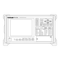
Anritsu MP1570A Operation Manual (772 pages)
SONET/SDH/PDH/ATM Analyzer
Brand:
Anritsu
| Category:
Measuring Instruments
| Size: 5 MB
Table of Contents
Table of Contents
12
Section1 General
15
Interface Function
17
Typical System up
18
Section 2 Gpib Interface
19
Section 2 GPIB Interface
20
GPIB Interface Function
21
Device Message List
22
Bus Command
23
GPIB Cable Connection
24
GPIB Setting
25
Bus Initialization
27
Device Initialization
27
Message Initialization
27
Device Initialization
28
Device Status at Power on
28
Section 3 Rs-232C Interface
29
Section 3 RS-232C Interface
30
Device Message List
31
RS-232C Cable Connection
32
RS-232C Setting
33
Device Initialization
35
Device Status at Power on
35
Section 4 Ethernet Interface
37
Device Message List
39
Initialization of Ethernet Board
41
Network Connection and Data Flow
47
Section 5 Listener Input Format
49
Section 5 Listener Input Format
50
Listener Input Program Message Format
51
Functional Element of Program Message
54
Terminated Program Message
54
Program Massage Terminator
55
Program Message
56
White Space
56
Program Message Unit Separator
57
Program Message Unit
58
Query Message Unit
58
Command Program Header
60
Query Program Header
63
Program Header Separator
64
Programdataseparator
64
Program Data Format
65
Character Program Data
66
Decimal Numeric Program Data
66
Boolean Program Data
67
String Program Data
68
Section 6 Talker Output Format
69
Section 6 Talker Output Format
70
Talker Output Response Message Format
71
Functional Element of Response Message
72
Response Massage Terminator
72
Terminated Response Message
72
Response Massage
73
Response Massag Unit
74
Response Massag Unit Separator
74
Response Data Separator
75
Response Data
76
Section 7 IIEEE488.2 Common Command
79
Section 8 Status Report
89
Section 8 Status Report
90
MP1570A Status Register Configuration
91
IEEE488.2 Specified Status Register
94
SCPI Specified Status Register
96
MP1570A Unique Status Register
97
Status Register Read, Write and Clear
106
Status Register Read, Write and Clear
107
Section 9 Scpi Overview
109
Command Configuration
111
Overview
111
Command Description Method
112
Command Combination
113
Parameter
114
Section 10 Detailed Device Message
115
Response Format
117
Buffer Size
119
Equipment Unique Command
119
Instrument Subsystem
121
Source Subsystem
125
Advertisement
Anritsu MP1570A Operation Manual (509 pages)
SONET/SDH/PDH/ATM Analyzer
Brand:
Anritsu
| Category:
Measuring Instruments
| Size: 7 MB
Table of Contents
Table of Contents
33
Product Outline
38
Features
39
Equipment Configuration
40
Equipment Configuration with Standard Accessories
40
Plug-In Unit Configuration
41
Interface Unit Configuration
43
Application Software Configuration
44
Section 2 Preparations before Use
46
Distance between Fan Ventilation Grills
48
Installation Site Environmental Conditions
48
Power Voltage
49
Connecting Other Devices
50
Connecting the Peripherals
50
Inserting an Interface Unit
51
Inserting and Removing an Interface Unit
51
Removing an Interface Unit
52
Inserting and Removing the Plug-In Unit
53
Inserting the Plug-In Unit
53
Removing the Plug-In Unit
55
Slots for Inserting Plug-In Units
57
Inserting and Removing the GPIB/232C Board
59
Inserting the Boards
59
Video Output Board and Ethernet Board
59
Removing the Board
60
In the Case of Dsn
61
Units and Optional Items Required for TX and RX Signals
61
In the Case of SONET
62
Sts1
62
Sts3/Sts12
66
Concatenation Mapping
82
CID Pattern and Non-Frame Pattern
83
Section 3 Panel Description
84
Section 3 Panel Description
85
Description of MP1570A Panel
86
Description of MP1570A Unit Panel
86
Front Panel
87
Rear Panel
91
Right Side Panel
95
Description of Video Output Board Panel
97
Description of Ethernet Board Panel
98
Description of Plug-In Unit Panel
99
MP0121A 2/8/34/139/156M Unit
99
MP0122A 1.5/45/52M Unit
100
MP0122B 1.5/45/52/52M (1.31) Unit
101
Description of the Interface Unit Panel
103
MP0105A CMI Unit
103
MP0108A NRZ Unit
104
MP0111A Optical 156M/622M (1.31) Unit
105
MP0112A Optical 156M/622M (1.55) Unit
106
MP0113A Optical 156M/622M (1.31/1.55) Unit
107
Section 4 Screen Description and Parameter Setting
110
Main Screen
112
Main Screen Configurations
112
Main Screen Selection
112
Main Screen Layout
114
Subscreens
116
Subscreens of 'Setup' Main Screen
116
Subscreens of 'Result' Main Screen
117
Subscreens of 'Test Menu' Main Screen
117
Subscreens of 'Analyze' Main Screen
118
Selecting a Subscreen
119
Setting Parameters through Windows
120
Setting through Item Selection Window
120
Setting 'Yes/No' Dialog Box
121
Setting through Numeric Entry Window
122
Setting through Character Entry Window
123
One-Shot Entry
125
Section 5 Basic Setting and Application Examples of Connection
126
Section 5 Basic Setting and Application Examples of Connection
127
Setting Basic Parameters
128
Dsn Monitoring
133
Initial Setting
134
SONET Monitoring
135
(Measurement of LTE Output through a Coupler)
136
Initial Setting
137
SONET Monitoring (Through-Mode Monitoring)
139
SONET Monitoring (Through-Mode Monitoring)
140
Initial Setting
141
Connection
143
Loop Back Test
143
Loop-Back Test
143
Initial Setting
145
End-To-End Measurement
147
End-To-End Measurement
148
Initial Setting
149
MUX Evaluation Test
151
MUX Evaluation Test
154
Connection
155
DEMUX Evaluation Test
156
Initial Setting
157
Section 6 Other Settings about the Measurement
162
Setting the Measurement Channel
164
Setting a Test Pattern
165
Setting of Trigger Output and Alarm Detection/Removal Condition
166
Editing SONET Overhead
167
H1 Byte and H2 Byte
167
K1 Byte and K2 Byte
168
S1 Byte
168
Other Overheads
169
Editing the Overhead
171
Setting Path Trace
173
Changing the Overhead Data Per Frame
174
Setting the Order Wire and the DCC Interface
175
Setting the Orderwire
175
Setting the Orderwire and the DCC Interface
175
Setting the DCC Interface
176
Editing Dummy Channel
177
Setting a Dummy of the Main Channel
177
Setting Path Overhead
177
Setting STS Pointer and VT Pointer
178
Setting the Path Trace
179
Setting the Mixed Payload
180
Setting Dummy STS
181
Setting the Tandem Connection
182
Setting the Type
182
Editing the Tandem Connection Byte
183
Setting the Measurement Conditions
185
Selecting the Signalling Pattern
186
Editing the Signalling Bits
187
Setting the CID Pattern
189
Bit Rate : Pdh/Dsn (2/8/34/139M, 1.5/45M)
190
Setting the Non Frame Pattern
190
Bit Rate : SONET(52/156/622M)
191
Adding Alarm
192
Adding Error and Alarm
192
Adding Error
193
Setting Pointer
194
Changing Pointer by Justification
195
Offsetting Payload by C Bit
196
Section 7 Measurement and Analysis
198
Continuity Test of All Channels by Trouble Search Function
200
Setting and Starting Search
200
Displaying Search Result
202
Analysis of the Search Results
204
Detected Error and Alarm Data for each Channel
204
Display of NG Paths (Paths for Which Errors and Alarms Were Detected)
207
(Measurement of One Channel on a Mapping Route)
208
Manual Measurement
208
Setting and Starting the Measurement
208
Displaying the Error and Alarm Measurement Results
209
Display of the B2 Error Measurement Results
212
History Display of the Errors and Alarms
212
Displaying the Error and Alarm of
213
VT Channel
213
Analysis of the Error and Alarm Measurement Results
214
Displaying the Justification Count
217
Display of Performance Measurement Results
219
Selecting Performance
219
Measurement
220
When You Select G.821 for Performance
221
When You Select G.826 for Performance
222
When You Select M.2100 for Performance
223
When You Select M.2101 for Performance
224
When You Select M.2110 for Performance
225
When You Select M.2120 for Performance
227
Error Performance Check
228
Delay Measurement
229
Displaying the Measured Results
229
Setting and Starting the Measurement
229
Pointer Sequence Test
231
Capturing Overheads
233
Monitor
235
Monitoring Overheads
235
Monitoring the Pointer and K1/K2 Bytes
236
Monitoring the Path Trace
238
Monitoring the Payload
239
Monitoring the Dsn Frame
241
Measuring the Optical Power
242
Measuring the Frequency of the Received Signal
243
Real Time Monitor of Frequency
243
Displaying the Deviation of the Frequency
244
Overhead Tests
245
OH BERT Test
248
PTR 64 Frame
250
OH Add/Drop
253
APS (Automatic Protection Switch) Test
254
Setting the Protection Protocol
254
Generating APS Sequence Pattern
255
APS Sequence Capture
257
Measurement of Line Switching Time
260
Frame Memory and Frame Capture
263
Frame Memory
264
Frame Capture
267
Initial Setting
269
IP over SDH
269
Switching IP Measurement Screen
269
Generating IP Packet
270
Capturing IP Packet
273
Displaying Captured IP Packets
274
Sequence Test
276
Setting Measurement Sequence
276
Displaying and Analyzing Measurement Results
277
Section 8 Other Functions
280
Selection of Either SDH or SONET Display
282
Setting the System
282
Setting the Buzzer
283
Setting the Orderwire (Voice Entry)
283
Setting the Clock
284
Setting the Graph Resolution
284
Setting the GPIB Interface
285
Setting the RS-232C Interface
285
Auto. Setup
286
Zooming up the Error and Alarm Measurement Results
287
Saving and Reading the Data
289
Saving the Measurement Conditions
289
Reading the Measured Results
290
Overwriting the Measurement Conditions
291
Renaming the Measurement Conditions
292
Deleting the Measurement Conditions
293
Saving the Analysis Graph Data
294
Reading out the Analysis Graph Data
295
Deleting the Analysis Graph Data
296
Deleting the Entire Analysis Graph Data
297
Printing
298
Printing the Screen Data
299
Automatic Printing of Measurement Data
300
Floppy Disk
304
Saving Data Onto a Floppy Disk
304
Reading out Data from a Floppy Disk
306
Creating a Directory
307
Deleting a File or a Directory
307
Formatting a Floppy Disk
308
Renaming a File
308
Description of 'Setup : Floppy Disk' Screen
309
Help Function
310
Screen Copy
311
Section 9 Performance Test
312
Section 9 Performance Test
313
Required to Execute Performance Test
314
Checking the CPU and Peripherals
315
Selftest Items
315
Checking the Built-In Printer
316
Checking MP1570A
317
Checking the Interface Unit
318
2/8/34/139/156M CMI/HDB3 Output Waveform
319
Connection
319
Testing Procedures
320
Pulse Mask (2/8/34/139/156M)
321
45/52M AMI/B8ZS/B3ZS Output Waveform
327
Connection
327
Testing Procedure
328
Pulse Mask (1.5/45/52M)
329
Connection
331
Optical Output Waveform
331
Pulse Mask (52M)
332
Testing Procedure
332
Connection
333
MP0105A CMI Unit Output Waveform
333
Testing Procedure
333
Connection
335
MP0108A NRZ Unit Output Waveform
335
Testing Procedure
335
Connection
337
MP0111A Optical 156/622M (1.31) Unit Output Waveform
337
Testing Procedure
337
Pulse Mask (156/622M)
338
Connection
339
MP0112A Optical 156/622M (1.55) Unit Output Waveform
339
Testing Procedure
339
Connection
340
MP0113A Optical 156/622M (1.31/1.55) Unit Output Waveform
340
Testing Procedure
340
Appendix A Specifications
342
Appendix B Options
374
Appendix C Accessories
380
Appendix D Initial Values
383
Appendix E Alarm Detection and Removal Conditions
398
Appendix F Performance Measurement
402
Appendix G Selftest Error Codes
440
Appendix H Daily Maintenance, Storage and Transportation
498
Appendix I Setting the Built-In Printer Paper
500
Appendix J Mounting the Protective Cap of the Optical Connector
504
Appendix K Revision Numbers of Optional Items and Software
506
Appendix L Installation
508
Advertisement
Related Products
Anritsu MP1763C
Anritsu MP1632C
Anritsu Bit Master MP1026B
Anritsu MP1595A
Anritsu MP1800A
Anritsu MP1797A
Anritsu Bit Master MP1026A
Anritsu MP1220A
Anritsu SQA-R MP1900A
Anritsu MP1900A Series
Anritsu Categories
Measuring Instruments
Test Equipment
Portable Generator
Control Unit
Thermometer
More Anritsu Manuals
Login
Sign In
OR
Sign in with Facebook
Sign in with Google
Upload manual
Upload from disk
Upload from URL