
Related Manuals for Anritsu Bit Master MP1026A


Summary of Contents for Anritsu Bit Master MP1026A
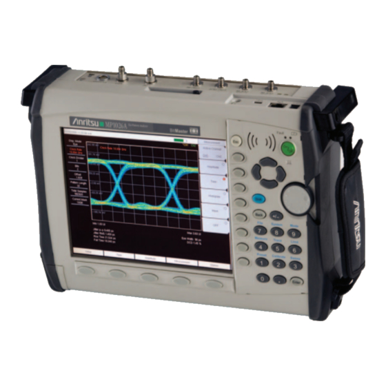
- Page 1 Maintenance Manual Bit Master MP1026A Eye Pattern Analyzer Anritsu Company P/N: 10580-00171 490 Jarvis Drive Revision: A Morgan Hill, CA 95037-2809 Printed: August 2008 Copyright 2008 Anritsu Company...
- Page 2 Anritsu is not liable for consequential damages. LIMITATION OF WARRANTY The foregoing warranty does not apply to Anritsu connectors that have failed due to normal wear. Also, the warranty does not apply to defects resulting from improper or inadequate maintenance by the Buyer, unauthorized modification or misuse, or operation outside of the environmental specifications of the product.
- Page 3 Some or all of the following five symbols may or may not be used on all Anritsu equipment. In addition, there may be other labels attached to products that are not shown in the diagrams in this manual.
- Page 4 For Safety Warning Always refer to the operation manual when working near locations at which the alert mark, shown on the left, is attached. If the operation, etc., is performed without heeding the advice in the operation manual, there is a risk of personal injury.
-
Page 5: Table Of Contents
Table of Contents Chapter 1—Introduction Introduction ..............1-1 Description . - Page 6 PN: 10580-00171 Revision A MP1026A MM...
-
Page 7: Chapter 1-Introduction
Chapter 1 — Introduction Introduction This manual provides maintenance instructions for the Bit Master Model MP1026A Eye Pattern Analyzer. The manual provides operational tests, performance verification procedures, battery pack information, part replacement procedures, and a list of replaceable parts and assemblies. Appendix A contains a blank test record to copy for recording measured values. -
Page 8: Recommended Test Equipment
Any (quantity 2) cable The instructions in Chapter 2 and Chapter 3 are written based on the use of an Anritsu Model MP1763x Pulse Pattern Generator (PPG). An Anritsu Model MP1800A Signal Quality Analyzer with the following suggested configurations may substitute for the Anritsu MP1763x PPG. -
Page 9: Chapter 2-Operational Tests
Chapter 2 — Operational Tests The tests in this chapter are confidence checks which help ensure that the MP1026A is functioning properly. To verify conformance to specifications, perform the tests in Chapter 3, Performance Verification Tests. Note Using an external power supply during operational tests of the MP1026A is recommended. Application Self-Test 1. - Page 10 2-2 Clock Trigger Frequency Lock Test Operational Tests 5. Press the Shift key and then the Preset key. Select the Preset soft key to preset the MP1026A. 6. Press the Time soft key and then select Acquire Clock Rate soft key. 7.
-
Page 11: Chapter 3-Performance Verification Tests
Chapter 3 — Performance Verification Tests The performance verification tests in this chapter ensure that the instrument is capable of making measurements to published accuracy specifications. A blank performance verification test record (including specifications) is provided in Appendix A. Make Appendix A, Test Record and use it to record measured values. - Page 12 3-1 Bandwidth Verification Performance Verification Tests 7. Adjust the level of the MG3694X so that the power meter reads –10.0 dBm ± 0.1 dB. 8. On the MP1026A, press the Setup soft key and set the Display Mode to Pulse. 9.
-
Page 13: Amplitude Accuracy Verification
Performance Verification Tests 3-2 Amplitude Accuracy Verification Amplitude Accuracy Verification 1. Restore the MP1026A to factory settings by pressing the Shift key and then the Preset key, then press the Preset soft key. 2. Press the Time soft key and set the Clock Rate to 10.0 GHz. Confirm that the Divide Ratio is 1. 3. - Page 14 3-2 Amplitude Accuracy Verification Performance Verification Tests 11. Adjust the voltage output of the power supply so that the display reads +420mV. The first DC voltage in Table 3-1. 12. Press the Measurement soft key on the MP1026A and select Histogram. 13.
-
Page 15: Rms Noise Verification
Performance Verification Tests 3-3 RMS Noise Verification RMS Noise Verification 1. Restore the MP1026A to factory settings by pressing the Shift key and then the Preset key, then press the Preset soft key. 2. Press the Shift key and then the Calibrate key. Select the Calibrate Amplitude soft key and then press the Enter key to perform an amplitude calibration. -
Page 16: Clock Recovery (Cru) Rms Jitter Verification (Option 2)
3-5 Clock Recovery (CRU) RMS Jitter Verification (Option 2) Performance Verification Tests 5. Press the Setup soft key and set the MP1026A as follows: Display Mode to Eye Channel 2 to Off Sampling and Accumulation to Infinite Accumulation 6. Press the Time soft key and set the Clock Rate to 10 GHz. 7. - Page 17 Performance Verification Tests 3-5 Clock Recovery (CRU) RMS Jitter Verification (Option 2) 3. Connect the PPG clock output to the ≥1 GHz CLK IN connector of the MP1026A. 4. Connect the PPG Data signal to the CRU IN connector. 5. Connect an RF cable between CRU OUT connector and CH2 Input connector. 6.
- Page 18 3-5 Clock Recovery (CRU) RMS Jitter Verification (Option 2) Performance Verification Tests PN: 10580-00171 Revision A MP1026A MM...
-
Page 19: Chapter 4-Battery Information
Chapter 4 — Battery Information The following information relates to the care and handling of the Anritsu 633-44 battery pack and Lithium-Ion batteries in general. • The 633-44 battery pack supplied with the MP1026A may need charging before use. Before using the... -
Page 20: Battery Pack Removal And Replacement
4-2 Battery Pack Removal and Replacement Battery Information Battery Pack Removal and Replacement This section provides instructions for the removal and replacement of the MP1026A battery pack. Many of the procedures in this section are generic, and apply to many similar instruments. Photos and illustrations used are representative and may show instruments other than the MP1026A. - Page 21 Battery Information 4-2 Battery Pack Removal and Replacement 4. With the battery access door completely removed, grasp the lanyard of the battery and pull the battery straight out of the unit as shown in Figure 4-4. Figure 4-4. Removing the Battery 5.
- Page 22 4-2 Battery Pack Removal and Replacement Battery Information PN: 10580-00171 Revision A MP1026A MM...
-
Page 23: Chapter 5-Remove And Replace Procedures
Only qualified Service personnel should attempt to perform repairs on this instrument. During the warranty period, opening of the case by non-Anritsu Service personnel will void the warranty. Extreme care must be used when handling internal assemblies. Careless handling will cause damage. -
Page 24: Opening The Mp1026A Case
For all assemblies, installation of the new assemblies is the opposite of removal. The main PCB and oscilloscope PCB are factory-repairable exchange assemblies, which should be returned to Anritsu promptly for credit. AC adapters, batteries, LCDs, keypad parts, and non-electrical parts are not exchange assemblies and need not be returned to Anritsu. -
Page 25: Replacing The Rtc Battery
Remove and Replace Procedures 5-3 Replacing the RTC Battery Replacing the RTC Battery 1. If the RTC battery is discharged, Self-Test Failed, Contact Customer Support may appear at boot-up. 2. Once the case is open, no further disassembly is required. The location of the battery is shown in Figure 5-2. -
Page 26: Removing The Main Pcb And Display Assemblies
5-4 Removing the Main PCB and Display Assemblies Remove and Replace Procedures Removing the Main PCB and Display Assemblies 1. Push the external CF card ejector button to the in position. 2. Unplug the cables to the fan, battery pack connector, and knob from the main PCB. Remove the 9 screws around the PCB edge to release the PCB/LCD assembly from the case. -
Page 27: Removing The Oscilloscope Pcb
Remove and Replace Procedures 5-6 Removing the Oscilloscope PCB Removing the Oscilloscope PCB Figure 5-4 identifies the oscilloscope PCB. When this board is to be replaced, retain the cables and cover plate for reuse on the replacement board. Follow the steps below to remove the board from the case. Figure 5-4. -
Page 28: Replacing Keypad Assemblies
5-7 Replacing Keypad Assemblies Remove and Replace Procedures Replacing Keypad Assemblies Replacing the Main Keypad Membrane This procedure provides instructions for removing and replacing the main keypad (numeric) membrane and PCB. All keypad parts can be replaced without opening the MP1026A case. 1. -
Page 29: Replacing The Main Keypad Pcb Assembly
Remove and Replace Procedures 5-7 Replacing Keypad Assemblies Replacing the Main Keypad PCB Assembly 1. Disconnect the function key flexible switchpad from J2 of the keypad PCB by carefully lifting the locking tab on connector J2 to release the flexible switchpad (Figure 5-6). -
Page 30: Function Key Membrane And Switchpad Replacement
5-8 Function Key Membrane and Switchpad Replacement Remove and Replace Procedures Function Key Membrane and Switchpad Replacement This procedure provides instructions for replacing the function keys (5 keys beneath the LCD) membrane and switchpad. All keypad parts can be replaced without opening the MP1026A case. 1. -
Page 31: Chapter 6-Troubleshooting
Boot-up Problems Unit cannot boot-up, no activity occurs when On/Off key is pressed: 1. Battery may be fully discharged. Use an external charger (Anritsu part number 2000-1374) to charge a completely discharged battery. 2. Battery may be the wrong type. Ensure the battery has an Anritsu label. - Page 32 6-1 Boot-up Problems Troubleshooting Fan or Temperature warnings: 1. Ensure air intake and outlet holes are not obstructed. 2. Refer to the User’s Guide (Appendix A) for fan operation information. 3. Replace the fan. 4. Replace the main PCB. Battery Pack Charging Problems: Refer to Chapter 4, Battery Information.
-
Page 33: Appendix A-Test Records
Appendix A — Test Records This appendix provides test records that can be used to record the performance of the MP1026A. Please make a copy of the following Test Record pages and document the measured values each time a Performance Verification is performed. - Page 34 Test Records MP1026A Firmware Revision: Operator: Serial Number: Options: Date: Bandwidth Verification (Specification: 3 dB (Half-Power) Point ≥ 20 GHz) 100 MHz Reference Voltage: ____________ mV peak-to-peak Computed 3 dB (Half-Power) Point: ____________ mV peak-to-peak 18 GHz ____________ mV peak-to-peak 19 GHz ____________ mV peak-to-peak 20 GHz ____________ mV peak-to-peak 21 GHz ____________ mV peak-to-peak...
- Page 35 Test Records MP1026A Firmware Revision: Operator: Serial Number: Options: Date: Amplitude Accuracy Verification Input DC Channel Scale Offset Measured Value Upper spec Lower spec Voltage (mV) (mV/div) (Mean) (mV) (mV) –2.5 –15 –12 –18 –30 –26 –34 –30 –26 –34 –60 –55 –65...
- Page 36 Test Records MP1026A Firmware Revision: Operator: Serial Number: Options: Date: RMS Noise Verification Measured Value Specification ≤ 1.75 mV CH1: CH2: RMS Jitter Verification Measured Value Specification ≤ 1.5 ps RMS Jitter: CRU RMS Jitter Verification (Option 2) Measured Value Specification Std Dev: ≤...
- Page 40 Anritsu Company 490 Jarvis Drive Printed on Recycled Paper with Vegetable Soybean Oil Ink Morgan Hill, CA 95037-2809 http://www.anritsu.com/...
Need help?
Do you have a question about the Bit Master MP1026A and is the answer not in the manual?
Questions and answers