Vega vegaflex 83 Operating Instruction
Tdr sensor for continuous level and interface measurement of liquids
Hide thumbs
Also See for vegaflex 83:
- Operating instructions manual (100 pages) ,
- Quick setup manual (20 pages) ,
- Operating instructions (4 pages)
Table of Contents
Advertisement
Quick Links
Download this manual
See also:
Operating Instructions
Advertisement
Table of Contents

Related Manuals for Vega vegaflex 83


Summary of Contents for Vega vegaflex 83
-
Page 1: Operating Instructions
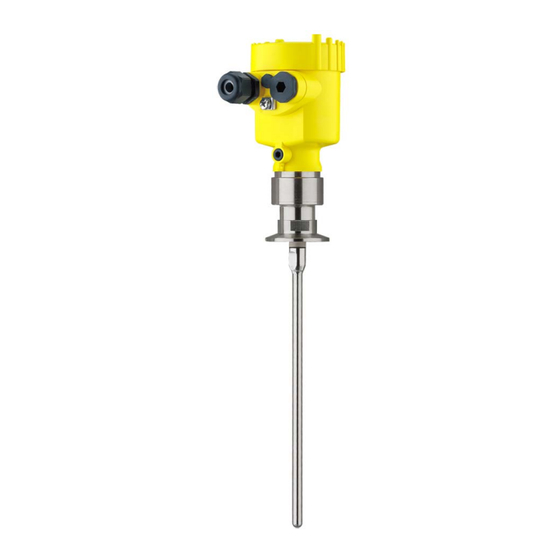
Operating Instructions TDR sensor for continuous level and interface measurement of liquids VEGAFLEX 83 Profibus PA Polished rod probe Document ID: 44223... -
Page 2: Table Of Contents
Parameter adjustment with PACTware ................51 Set up with the quick setup ..................... 52 Saving the parameter adjustment data ................57 Set up with other systems DD adjustment programs ....................58 Diagnostics and service Maintenance ........................59 VEGAFLEX 83 • Profibus PA... - Page 3 Safety instructions for Ex areas Please note the Ex-specific safety information for installation and op- eration in Ex areas. These safety instructions are part of the operating instructions manual and come with the Ex-approved instruments. Editing status: 2014-03-31 VEGAFLEX 83 • Profibus PA...
-
Page 4: About This Document
Action This arrow indicates a single action. Sequence of actions Numbers set in front indicate successive steps in a procedure. Battery disposal This symbol indicates special information about the disposal of bat- teries and accumulators. VEGAFLEX 83 • Profibus PA... -
Page 5: For Your Safety
During work on and with the device the required personal protective equipment must always be worn. Appropriate use VEGAFLEX 83 is a sensor for continuous level measurement. You can find detailed information about the area of application in chapter "Product description". -
Page 6: Namur Recommendations
The environment management system is certified according to DIN EN ISO 14001. Please help us fulfill this obligation by observing the environmental instructions in this manual: • Chapter "Packaging, transport and storage" • Chapter "Disposal" VEGAFLEX 83 • Profibus PA... -
Page 7: Product Description
Test certificate (PDF) - optional Go to www.vega.com, "VEGA Tools" and "Instrument search". Enter the serial number. Alternatively, you can access the data via your smartphone: • Download the smartphone app "VEGA Tools" from the "Apple App Store" or the "Google Play Store" VEGAFLEX 83 • Profibus PA... -
Page 8: Principle Of Operation
– Ex-specific "Safety instructions" (with Ex versions) – if necessary, further certificates Principle of operation The VEGAFLEX 83 is a level sensor with polished rod probe for Application area continuous level or interface measurement, particularly suitable for applications in the food processing and pharmaceutical industry. - Page 9 Upon reaching the product surface, a part of the microwave im- pulses is reflected. The other part passes through the upper product and is reflected by the interface. The running times to the two product layers are processed by the instrument. VEGAFLEX 83 • Profibus PA...
- Page 10 Example: upper medium dielectric constant 2, lower medium at least dielectric constant 12. Gas phase (L3) • Air or gas mixture • Gas phase - dependent on the application, gas pahse does not always exist (d2 = 0) VEGAFLEX 83 • Profibus PA...
-
Page 11: Packaging, Transport And Storage
(Document-ID 27835). The interface adapter VEGACONNECT enables the connection of VEGACONNECT communication-capable instruments to the USB interface of a PC. For parameter adjustment of these instruments, the adjustment software PACTware with VEGA-DTM is required. VEGAFLEX 83 • Profibus PA... - Page 12 3 Product description You can find further information in the operating instructions "Interface adapter VEGACONNECT" (Document-ID 32628). VEGADIS 81 The VEGADIS 81 is an external display and adjustment unit for VEGA plics sensors. ® For sensors with double chamber housing the interface adapter "DIS- ADAPT"...
- Page 13 3 Product description If you mount the VEGAFLEX 83 in a bypass tube or standpipe, you Spacer have to avoid contact to the bypass tube by using a spacer at the probe end. You can find additional information in the operating instructions manual "Centering".
-
Page 14: Mounting
"Technical data" as well as on the type label. Mounting instructions Mount VEGAFLEX 83 in such a way that the distance to vessel instal- Installation position lations or to the vessel wall is at least 300 mm (12 in). In non-metallic vessels, the distance to the vessel wall should be at least 500 mm (19.7 in). - Page 15 When installing rod or cable probes in vessels without metal walls, e.g. in plastic vessels, the measured value can be influenced by strong electromagnetic fields (emitted interference according to EN 61326: class A). In this case, use a probe with coaxial version. VEGAFLEX 83 • Profibus PA...
- Page 16 You can find further information under "Setup procedure". _ < DN40 ... DN150 _ < > DN150 ... DN200 Fig. 6: Mounting socket When welding the socket, make sure that the socket is flush with the vessel top. VEGAFLEX 83 • Profibus PA...
- Page 17 - measurement in these areas is not possible (dead band). The length of the cable can be used all the way to the end only when measuring conductive VEGAFLEX 83 • Profibus PA...
- Page 18 You can find further information in the supplementary instructions of the rod extension. Autoclaved version For use in an autoclave, e.g. for sterilization, the VEGAFLEX 83 is available as autoclaved version. Hence you can separate the housing from the process fitting.
- Page 19 ø w ø w DIN DN25 DN32 DN40 / 1" 1 1/2" ø 50,5 DIN DN50 / 2" ø 64 DIN DN65 / 3" ø 91 Fig. 9: Autoclaved version 1 Groove nut 2 Process fitting 3 Cover with groove nut VEGAFLEX 83 • Profibus PA...
-
Page 20: Connecting To Power Supply
The voltage supply and signal output are connected via the spring- loaded terminals in the housing. Connection to the display and adjustment module or to the interface adapter is carried out via contact pins in the housing. VEGAFLEX 83 • Profibus PA... - Page 21 4. Remove approx. 10 cm (4 in) of the cable mantle, strip approx. 1 cm (0.4 in) of insulation from the ends of the individual wires 5. Insert the cable into the sensor through the cable entry Fig. 10: Connection steps 5 and 6 - Single chamber housing Fig. 11: Connection steps 5 and 6 - Double chamber housing VEGAFLEX 83 • Profibus PA...
-
Page 22: Wiring Plan, Single Chamber Housing
For display and adjustment module or interface adapter Selection switch for bus address For external display and adjustment unit 5 Ground terminal for connection of the cable screen Wiring plan, double chamber housing The following illustrations apply to the non-Ex as well as to the Ex-ia version. VEGAFLEX 83 • Profibus PA... - Page 23 For display and adjustment module or interface adapter For external display and adjustment unit 4 Ground terminal for connection of the cable screen Information: The use of an external display and adjustment unit and a display and adjustment module in parallel in the connection compartment is not supported. VEGAFLEX 83 • Profibus PA...
-
Page 24: Double Chamber Housing With Dis-Adapt
1 DIS-ADAPT Internal plug connection Plug connector M12 x 1 Assignment of the plug connector Fig. 17: View to the plug connector M12 x 1 Pin 1 Pin 2 Pin 3 Pin 4 VEGAFLEX 83 • Profibus PA... -
Page 25: Wiring Plan - Version Ip 66/Ip 68, 1 Bar
When the instrument is shipped, address 126 is adjusted. This ad- dress can be used for function test of the instrument and for con- VEGAFLEX 83 • Profibus PA... -
Page 26: Switch-On Phase
The addressing procedure is described in the operating instructions manual "Display and adjustment module. Switch-on phase After VEGAFLEX 83 is connected to the bus system, the instrument carries out a self-test for approx. 30 seconds. The following steps are carried out: •... -
Page 27: Set Up With The Display And Adjustment Module
The display and adjustment module is powered by the sensor, an ad- ditional connection is not necessary. Fig. 21: Installing the display and adjustment module in the electronics compart- ment of the single chamber housing VEGAFLEX 83 • Profibus PA... -
Page 28: Adjustment System
Adjustment system Fig. 23: Display and adjustment elements 1 LC display Adjustment keys • Key functions [OK] key: – Move to the menu overview VEGAFLEX 83 • Profibus PA... -
Page 29: Parameter Adjustment - Quick Setup
Any values not confirmed with [OK] will not be saved. Switch-on phase After switching on, the VEGAFLEX 83 carries out a short self-test where the device software is checked. The output signal transmits a fault signal during the switch-on phase. - Page 30 Enter the suitable distance value in m for the empty vessel (e.g. distance from the flange to the probe end) corresponding to the per- centage value. The distance refers tot he sensor reference plane (seal surface of the process fitting). VEGAFLEX 83 • Profibus PA...
- Page 31 They represent the correlation between the level percentage and vessel volume. The linearization applies for the measured value indication and the current output. By activating the suitable curve, the percentage vessel volume is displayed correctly. VEGAFLEX 83 • Profibus PA...
-
Page 32: Parameter Adjustment - Extended Adjustment
Setup: Settings, e.g. measurement loop name, medium, application, vessel, adjustment, AI FB 1 Channel - Scaling - Damping, device units, false signal suppression, linearization Display: Language setting, settings for the measured value indication as well as lighting VEGAFLEX 83 • Profibus PA... - Page 33 Hardware addressing The hardware addressing is effective if an address <126 is set with the address selection switches on the electronics module of VEGAFLEX 83. Software addressing thus has no effect - only the set hardware address applies. Software addressing The software addressing is only effective if address 126 or higher is adjusted on the instrument with the address selection switches.
- Page 34 Setup - Application - Ap- In this menu item, you can select the application. You can choose plication between level measurement and interface measurement. You can also choose between measurement in a vessel or in a bypass or standpipe. VEGAFLEX 83 • Profibus PA...
- Page 35 This menu item is only available if you have selected interface meas- electric constant urement under the menu item "Application". In this menu item you can choose the type of medium of the upper medium. VEGAFLEX 83 • Profibus PA...
- Page 36 Enter the suitable distance value in m for the empty vessel (e.g. distance from the flange to the probe end) corresponding to the per- centage value. The distance refers tot he sensor reference plane (seal surface of the process fitting). VEGAFLEX 83 • Profibus PA...
- Page 37 A false signal suppression detects, marks and saves these false signals so that they are no longer taken into account for the level and interface measurement. We generally recommend carrying out a false signal suppression to achieve the best possible accuracy. This should VEGAFLEX 83 • Profibus PA...
- Page 38 By activating the appropriate curve, the volume per- centage of the vessel is displayed correctly. If the volume should not be displayed in percent but e.g. in l or kg, a scaling can be also set in the menu item "Display". VEGAFLEX 83 • Profibus PA...
- Page 39 D Vessel height +h Positive socket correction value -h Negative socket correction value Setup - AI FB1 Since the adjustment is very comprehensive, the menu points of Function Blocks 1 (FB1) were put together in a submenu. VEGAFLEX 83 • Profibus PA...
- Page 40 The damping applies to the level and interface measurement. The default setting is a damping of 0 s. Lock/release setup - Ad- In the menu item "Lock/unlock adjustment", you can protect the justment sensor parameters against unauthorized modification. The PIN is activated/deactivated permanently. VEGAFLEX 83 • Profibus PA...
- Page 41 In this menu item, you define the indication of the measured value Display - Displayed value on the display. You can display two different measured values. In this menu item, you define measured value 2. VEGAFLEX 83 • Profibus PA...
- Page 42 Values > 90 % indicate reliable measurement. If you have selected interface measurement under the menu item "Setup - Application", the peak values of the interface measurement are displayed in addition to the peak values of the level measurement. VEGAFLEX 83 • Profibus PA...
- Page 43 In this menu item you can simulate measured values via the current output. This allows the signal path to be tested, e.g. through down- stream indicating instruments or the input card of the control system. VEGAFLEX 83 • Profibus PA...
- Page 44 Additional settings - PIN Entering a 4-digit PIN protects the sensor data against unauthorized access and unintentional modification. In this menu item, the PIN is displayed or edited and changed. However, this menu item is only VEGAFLEX 83 • Profibus PA...
- Page 45 Setup Menu item Default value Modified value Block adjustment Released Measurement loop name Sensor Units Distance unit: mm Temperature unit: °C Probe length Length of the probe Ex factory Type of medium Liquid Application Level, vessel VEGAFLEX 83 • Profibus PA...
- Page 46 AI FB1 PV FTime AI FB1 Hi Hi Limit 3.402823E+38 % AI FB1 Hi Limit 3.402823E+38 % AI FB1 Lo Lo Limit -3.402823E+38 % AI FB1 Lo Limit -3.402823E+38 % AI FB1 Hysteresis 0.50 % VEGAFLEX 83 • Profibus PA...
- Page 47 Device memory - Measured value memory - Stop Not active recording when memory is full Additional adjustments Menu item Default value Modified value 0000 Date Actual date Time Actual time Time - Format 24 hours Probe type Device-specific VEGAFLEX 83 • Profibus PA...
- Page 48 AI FB3 Lo Limit -3.402823E+38 % AI FB3 Hysteresis 0.50 % AI FB3 Fail Safe Mode (behaviour in case of mal- Last Valid Out Value (last valid function) measured value) AI FB3 Fail Safe Value 0.00 % VEGAFLEX 83 • Profibus PA...
- Page 49 In exceptional cases, individual parameters can be modified in order to adapt the sensor to special requirements. Change the settings of the special parameters only after having con- tacted our service staff. VEGAFLEX 83 • Profibus PA...
-
Page 50: Saving The Parameter Adjustment Data
If it is necessary to exchange a sensor, the display and adjustment module is inserted into the replacement instrument and the data are likewise written into the sensor via the menu item "Copy sensor data". VEGAFLEX 83 • Profibus PA... -
Page 51: Setup With Pactware
Further setup steps are described in the operating instructions manu- al "DTM Collection/PACTware" attached to each DTM Collection and which can also be downloaded from the Internet. Detailed descrip- tions are available in the online help of PACTware and the DTMs. VEGAFLEX 83 • Profibus PA... -
Page 52: Set Up With The Quick Setup
The standard version is available as a download under www.vega.com/downloads and "Software". The full version is avail- able on CD from the agency serving you. Set up with the quick setup... - Page 53 2 Extended adjustment Maintenance Quick setup With quick setup you can carry out the parameter adjustment of VEGAFLEX 83 for your application in just a few simple steps. The assistant-driven adjustment includes the basic settings for simple, reliable setup and commissioning. Information: If the function is inactive, then possibly no instrument is connected.
- Page 54 Hardware addressing - The hardware addressing is effective if an address <126 is set with the address selection switches on the electronics module of VEGAFLEX 83. The software addressing is then no longer effective, only the set hardware address is valid.
- Page 55 The total level is also available as a measured value. • Superimposed gas phase present – Check if there is a superimposed gas phase in the vessel. This is always the case if the total level never touches the process fitting. • Properties VEGAFLEX 83 • Profibus PA...
- Page 56 Select whether or not the probe is immersed in the medium. Measured distance to the medium If the probe is immersed in the medium, you can enter here the meas- ured distance to the medium. VEGAFLEX 83 • Profibus PA...
-
Page 57: Saving The Parameter Adjustment Data
PIN is entered again. Saving the parameter adjustment data We recommend documenting or saving the parameter adjustment data via PACTware. That way the data are available for multiple use or service purposes. VEGAFLEX 83 • Profibus PA... -
Page 58: Set Up With Other Systems
Set up with other systems DD adjustment programs Device descriptions as Enhanced Device Description (EDD) are available for DD adjustment programs such as, for example, AMS™ and PDM. The files can be downloaded at www.vega.com/downloads under "Software". VEGAFLEX 83 • Profibus PA... -
Page 59: Diagnostics And Service
Changes in the measure- ment conditions during operation or buildup on the sensor can thus be recognized. The echo curve of the setup is stored via: • PC with PACTware/DTM • Control system with EDD VEGAFLEX 83 • Profibus PA... -
Page 60: Status Messages
This status message is inactive by default. It can be activated by the user via PACTware/DTM or EDD. Maintenance: Due to external influences, the instrument function is limited. The measurement is affected, but the measured value is VEGAFLEX 83 • Profibus PA... - Page 61 3 min. F113 – Error in the internal – Disconnect operating Bit 7 instrument communi- voltage briefly Communi- cation – Send instrument for cation error repair VEGAFLEX 83 • Profibus PA...
- Page 62 – Wait for the automatic end Simulation ac- after 60 mins. tive Out of specification The following table shows the error codes and text messages in the status message "Out of specification" and provides information on causes as well as corrective measures. VEGAFLEX 83 • Profibus PA...
- Page 63 – Clean the antenna – Change polarisation direc- tion – Use instrument with higher sensitivity M504 – Hardware defect – Check connections – Exchanging the electronics Error on an device inter- – Send instrument for repair face VEGAFLEX 83 • Profibus PA...
-
Page 64: Rectify Faults
Wherever the sensor displays a constant value, the reason could also be the fault setting of the current output to "Hold value" • In case of a too low level indication, the reason could be a line resistance that is too high VEGAFLEX 83 • Profibus PA... - Page 65 The sensor goes into – If possible, switch off the func- overfill protection mode. The time tion "Overfill protection" max. level (0 m distance) as well as the status message "Overfill protection" are output- ted. VEGAFLEX 83 • Profibus PA...
- Page 66 Fault description Error pattern Cause Rectification 1. Measured value – Min./max. adjustment not – Adapt min./max. adjustment shows a too low or too correct high level – Wrong linearization curve – Adapt linearization curve time VEGAFLEX 83 • Profibus PA...
- Page 67 100 % during filling signal suppression with con- densation/contamination in the close range by editing time – With bulk solids use radar sen- sor with purging air connection or flexible antenna cover VEGAFLEX 83 • Profibus PA...
-
Page 68: Exchanging The Electronics Module
24 hour service hotline Should these measures not be successful, please call in urgent cases the VEGA service hotline under the phone no. +49 1805 858550. The hotline is also available outside normal working hours, seven days a week around the clock. -
Page 69: Exchanging The Rod
4. Screw the new rod carefully by hand to the thread on the process fitting. 5. Exert counterforce manually and tighten the rod on the flat sur- faces with a torque of 6 Nm (4.43 lbf ft). VEGAFLEX 83 • Profibus PA... -
Page 70: Software Update
PC with PACTware • Current instrument software as file You can find the current instrument software as well as detailed information on the procedure under "www.vega.com/downloads" and "Software". Caution: Instruments with approvals can be bound to certain software versions. Therefore make sure that the approval is still effective after a software update is carried out. -
Page 71: How To Proceed If A Repair Is Needed
9 Diagnostics and service You can find detailed information at www.vega.com/downloads and "Approvals". How to proceed if a repair is needed You can find a repair form as well as detailed information on how to proceed at www.vega.com/downloads and "Forms and certificates". -
Page 72: Dismounting
Pass the instrument directly on to a spe- cialised recycling company and do not use the municipal collecting points. These may be used only for privately used products according to the WEEE directive. VEGAFLEX 83 • Profibus PA... -
Page 73: Supplement
4 m (13.12 ft) Ʋ Trimming accuracy - rod ±1 mm + 0.05 % of the rod length Lateral load with rod: ø 8 mm (0.315 in) 10 Nm (7.38 lbf ft) - polished All wetted parts VEGAFLEX 83 • Profibus PA... - Page 74 Sensor address 126 (default setting) Damping (63 % of the input variable) 0 … 999 s, adjustable Profibus PA profile 3.02 Number of FBs with AI (function blocks with analogue input) Default values Ʋ 1. FB VEGAFLEX 83 • Profibus PA...
- Page 75 Depending on the installation conditions, there can be deviations which can be rectified with an adaptation of the adjustment or a change of the measured value offset in the DTM service mode The dead bands can be optimizes by a false signal suppression. VEGAFLEX 83 • Profibus PA...
- Page 76 Temperature drift - Digital output ±3 mm/10 K relating to the max. measuring range or max. 10 mm (0.394 in) Additional deviation through electromag- < ±10 mm (< ±0.394 in) netic interference acc. to EN 61326 VEGAFLEX 83 • Profibus PA...
- Page 77 Time span after a sudden measuring distance change by max. 0.5 m in liquid applications, max 2 m with bulk solids applications, until the output signal has taken for the first time 90 % of the final value (IEC 61298-2). VEGAFLEX 83 • Profibus PA...
- Page 78 M20 x 1.5 (cable: ø 5 … 9 mm) tion cable Ʋ Cable entry ½ NPT Ʋ Blind plug M20 x 1.5; ½ NPT Connection cable Ʋ Wire cross-section 0.5 mm² (AWG 20) Ʋ Wire resistance < 0.036 Ω/m VEGAFLEX 83 • Profibus PA...
- Page 79 9 … 17.5 V DC FISCO model Ʋ Ex-ia instrument - Power supply 9 … 24 V DC ENTITY model Operating voltage U - illuminated display and adjustment module Ʋ Non-Ex instrument 13,5 … 32 V DC VEGAFLEX 83 • Profibus PA...
-
Page 80: Communication Profibus Pa
Instruments with approvals can have different technical specifications depending on the version. For that reason the associated approval documents of these instruments have to be carefully noted. They are part of the delivery or can be downloaded under www.vega.com, "VEGA Tools" and "Instrument search" as well as under www.vega.com/downloads and "Approvals". - Page 81 VE010BF5.GSD PA139702.GSD ries Cyclical data traffic The master class 1 (e.g. PLC) cyclically reads out measured values from the sensor during opera- tion. The below block diagram below shows which data can be accessed by the PLC. VEGAFLEX 83 • Profibus PA...
- Page 82 11 Supplement Fig. 52: VEGAFLEX 83: Block diagram with AI FB 1 … AI FB 3 OUT values TB Transducer Block FB 1 … FB 3 Function Block Module of the PA sensors For the cyclic data traffic, VEGAFLEX 83 provides the following modules: • AI FB1 (OUT) – Out value of the AI FB1 after scaling • AI FB2 (OUT) –...
- Page 83 -10 -11 -12 -13 -14 -15 -16 -17 -18 -19 -20 -21 -22 -23 Sign Significant Significant Exponent Significant (Exponent - 127) Value = (-1) (1 + Significant) Fig. 54: Data format of the measured value VEGAFLEX 83 • Profibus PA...
- Page 84 Hi-Alarm tive advisory alarm - high limited 0 x 8d good (non-cascade) - ac- Lo-Lo-Alarm tive critical alarm - low limited 0 x 8e good (non-cascade) - ac- Hi-Hi-Alarm tive critical alarm - high limited VEGAFLEX 83 • Profibus PA...
-
Page 85: Dimensions
11 Supplement 11.3 Dimensions The following dimensional drawings represent only an extract of all possible versions. Detailed dimensional drawings can be downloaded at www.vega.com/downloads under "Drawings". Plastic housing ~ 69 mm ~ 84 mm (2.72") (3.31") ø 79 mm ø 79 mm (3.11") - Page 86 ø 80 mm ø 79 mm (3.39") (3.15") (3.11") M16x1,5 M20x1,5/ ½ NPT M20x1,5/ M20x1,5/ ½ NPT ½ NPT Fig. 58: Housing versions in protection IP 66/IP 68 (0.2 bar) - with integrated display and adjustment module the housing is 9 mm/0.35 in higher Single chamber version, electropolished Single chamber version, precision casting Double chamber version, precision casting VEGAFLEX 83 • Profibus PA...
- Page 87 Fig. 59: Housing versions in protection IP 66/IP 68 (1 bar) - with integrated display and adjustment module the housing is 9 mm/0.35 in higher Single chamber version, electropolished Single chamber version, precision casting Double chamber version, precision casting VEGAFLEX 83, rod version ø 8 mm (0.315 in), polished ø 8 mm (0.32") Fig. 60: VEGAFLEX 83, rod version ø 8 mm (0.315 in), polished Sensor length, see chapter "Technical data" VEGAFLEX 83 • Profibus PA...
- Page 88 11 Supplement VEGAFLEX 83, rod version ø 8 mm (0.315 in), polished - autoclaved version ø 54 mm (2.13") ø w ø w DIN DN25 DN32 DN40 / 1" 1 1/2" ø 50,5 DIN DN50 / 2" ø 64 DIN DN65 / 3"...
- Page 89 Les lignes de produits VEGA sont globalement protégées par des droits de propriété intellec- tuelle. Pour plus d'informations, on pourra se référer au site www.vega.com. VEGA lineas de productos están protegidas por los derechos en el campo de la propiedad indus- trial. Para mayor información revise la pagina web www.vega.com.
- Page 90 12 Factory calibration date 50 – Electronics module 12 False signal suppression 37 Fault rectification 64 – Spacer 13 Reset 45 Functional principle 8 Scaling 40 Gas phase 35 Scaling unit 40 GSD file 81 VEGAFLEX 83 • Profibus PA...
- Page 91 Service hotline 68 Simulation 43 Software addressing 26, 33 Special parameters 49 Status bytes PA output value 84 Status messages - NAMUR NE 107 60 Telegram configuration 83 Type label 7 Type of medium 34 Units 34 VEGAFLEX 83 • Profibus PA...
- Page 92 Subject to change without prior notice © VEGA Grieshaber KG, Schiltach/Germany 2014 VEGA Grieshaber KG Phone +49 7836 50-0 Am Hohenstein 113...
Need help?
Do you have a question about the vegaflex 83 and is the answer not in the manual?
Questions and answers