Vega VEGAFLEX 81 Operating Instructions Manual
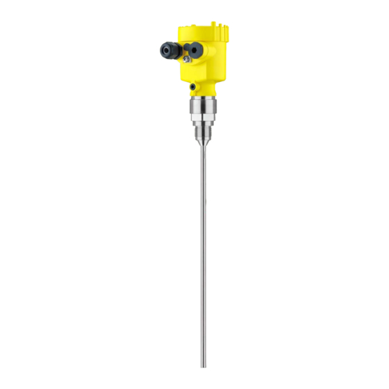
Tdr sensor for continuous level and interface measurement of liquids
Hide thumbs
Also See for VEGAFLEX 81:
- Operating instructions manual (100 pages) ,
- Quick setup manual (24 pages) ,
- Mounting instructions (20 pages)

Related Manuals for Vega VEGAFLEX 81


Summary of Contents for Vega VEGAFLEX 81
- Page 1 Operating Instructions TDR sensor for continuous level and interface measurement of liquids VEGAFLEX 81 Modbus and Levelmaster protocol Rod and cable probe Document ID: 51514...
-
Page 2: Table Of Contents
Set up with the quick setup ..................... 53 Saving the parameterisation data ................... 55 Diagnostics and servicing ....................56 Maintenance ........................56 Diagnosis memory ......................56 Status messages ......................57 Rectify faults ........................60 VEGAFLEX 81 • Modbus and Levelmaster protocol... - Page 3 10.8 Industrial property rights ....................97 10.9 Trademark ........................97 Safety instructions for Ex areas Take note of the Ex specific safety instructions for Ex applications. These instructions are attached as documents to each instrument with Ex approval and are part of the operating instructions. Editing status: 2020-01-24 VEGAFLEX 81 • Modbus and Levelmaster protocol...
-
Page 4: About This Document
Symbols used Document ID This symbol on the front page of this instruction refers to the Docu- ment ID. By entering the Document ID on www.vega.com you will reach the document download. Information, note, tip: This symbol indicates helpful additional infor- mation and tips for successful work. -
Page 5: For Your Safety
During work on and with the device, the required personal protective equipment must always be worn. Appropriate use VEGAFLEX 81 is a sensor for continuous level measurement. You can find detailed information about the area of application in chapter "Product description". Operational reliability is ensured only if the instrument is properly used according to the specifications in the operating instructions manual as well as possible supplementary instructions. -
Page 6: Eu Conformity
That is why we have introduced an environment management system with the goal of continuously improving company environmental pro- tection. The environment management system is certified according to DIN EN ISO 14001. Please help us fulfil this obligation by observing the environmental instructions in this manual: • Chapter "Packaging, transport and storage" • Chapter "Disposal" VEGAFLEX 81 • Modbus and Levelmaster protocol... -
Page 7: Product Description
Scope of this operating This operating instructions manual applies to the following instrument instructions versions: • Hardware from 1.0.0 • Software from 1.3.0 • Only for instrument versions without SIL qualification Type label The type label contains the most important data for identification and use of the instrument: VEGAFLEX 81 • Modbus and Levelmaster protocol... - Page 8 Alternatively, you can access the data via your smartphone: • Download the VEGA Tools app from the "Apple App Store" or the "Google Play Store" • Scan the DataMatrix code on the type label of the instrument or •...
-
Page 9: Principle Of Operation
3 Product description Principle of operation Application area The VEGAFLEX 81 is a level sensor with cable or rod probe for continuous level or interface measurement, suitable for applications in liquids. Functional principle - High frequency microwave pulses are guided along a steel cable or level measurement a rod. - Page 10 Example: upper medium dielectric constant 2, lower medium at least dielectric constant 12. Gas phase (L3) • Air or gas mixture • Gas phase - dependent on the application, gas phase does not always exist (d2 = 0) VEGAFLEX 81 • Modbus and Levelmaster protocol...
-
Page 11: Packaging, Transport And Storage
The integrated Bluetooth module (optional) enables wireless adjust- ment via standard adjustment devices. VEGACONNECT The interface adapter VEGACONNECT enables the connection of communication-capable instruments to the USB interface of a PC. VEGAFLEX 81 • Modbus and Levelmaster protocol... - Page 12 You can find further information in the operating instructions manual "Bypass tube VEGAPASS 81". Centering If you mount the VEGAFLEX 81 in a bypass tube or standpipe, you have to avoid contact to the bypass tube by using a spacer at the probe end. Fixing facility If there is a risk of the cable probe touching the vessel wall during operation due to product movements or agitators, etc., the measuring...
-
Page 13: Mounting
Prior to setup you have to replace these protective caps with ap- proved cable glands or close the openings with suitable blind plugs. Note: Process conditions For safety reasons, the instrument must only be operated within the permissible process conditions. You can find detailed information on VEGAFLEX 81 • Modbus and Levelmaster protocol... -
Page 14: Mounting Instructions
Mounting instructions Installation position Mount VEGAFLEX 81 in such a way that the distance to vessel instal- lations or to the vessel wall is at least 300 mm (12 in). In non-metallic vessels, the distance to the vessel wall should be at least 500 mm (19.7 in). - Page 15 In such cases, always carry out a false signal suppression after mounting. You can find further information under "Setup procedure". DN25 ... DN150 ≤ 150 mm (5.91") > DN150 ... DN200 ≤ 100 mm (3.94") Fig. 6: Mounting socket When welding the socket, make sure that the socket is flush with the vessel top. VEGAFLEX 81 • Modbus and Levelmaster protocol...
- Page 16 "Technical data". Keep in mind for the adjustment that the default setting for the measuring range refers to water. VEGAFLEX 81 • Modbus and Levelmaster protocol...
- Page 17 If durability is no problem, we recommend the use of uncoated metal standpipes. When the VEGAFLEX 81 is used in bypass tubes, contact with the tube wall must be avoided. We recommend for this purpose a cable probe with centering weight.
- Page 18 It does not matter if the standpipe is perforated or slotted for better mixing. Measuring probes can be mounted in standpipes up to DN 200. VEGAFLEX 81 • Modbus and Levelmaster protocol...
- Page 19 If durability is no problem, we recommend the use of uncoated metal standpipes. When the VEGAFLEX 81 is used in standpipes, contact with the tube wall must be avoided. We recommend for this purpose a cable probe with centering weight.
- Page 20 If there is a risk of the cable probe touching the vessel wall during operation due to product movements or agitators, etc., the measuring probe can be strained. For this purpose there is an internal thread (M12 or M8) in the gravity weight. VEGAFLEX 81 • Modbus and Levelmaster protocol...
- Page 21 In case of difficult installation conditions, for example in a socket, the probe can be suitably adapted with a rod extension. To compensate for the resulting changes in signal runtime, let the instrument determine the probe length automatically. You can find further information in the supplementary instructions of the rod and cable components. VEGAFLEX 81 • Modbus and Levelmaster protocol...
-
Page 22: Connecting To Power Supply And Bus System
On plastic housings, the NPT cable gland or the Conduit steel tube must be screwed into the threaded insert without grease. Max. torque for all housings, see chapter "Technical data". VEGAFLEX 81 • Modbus and Levelmaster protocol... -
Page 23: Connecting
6. Insert the wire ends into the terminals according to the wiring plan Information: Solid cores as well as flexible cores with wire end sleeves are insert- ed directly into the terminal openings. In case of flexible cores without end sleeves, press the terminal from above with a small screwdriver, the terminal opening is then free. When the screwdriver is released, the terminal closes again. VEGAFLEX 81 • Modbus and Levelmaster protocol... -
Page 24: Wiring Plan, Single Chamber Housing
Make sure that the slid switch (5) with all sen- sors of the chain is set to "off". With the last sensor you have to set the slide switch (5) to position "on". Please also take note of the information in the annex "Basics Mod- bus". VEGAFLEX 81 • Modbus and Levelmaster protocol... - Page 25 1 2 = Power supply 3 4 = Modbus Data 5 6 = Power supply addr. 7 8 = Modbus Data 5 6 7 8 Fig. 15: Electronics compartment - Connection with stub Voltage supply Signal output Ground terminal in the housing VEGAFLEX 81 • Modbus and Levelmaster protocol...
-
Page 26: Set Instrument Address
Available hardware addresses: • Hardware address - Levelmaster: 000 … 030 • Hardware address - Modbus: 000 … 245 Set the instrument address with the three rotary switches on the electronics module. VEGAFLEX 81 • Modbus and Levelmaster protocol... -
Page 27: Switch-On Phase
• Status byte goes to fault value Then the actual measured value is output to the signal cable. The value takes into account settings that have already been carried out, e.g. default setting. VEGAFLEX 81 • Modbus and Levelmaster protocol... -
Page 28: Set Up The Sensor With The Display And Adjustment Module
The display and adjustment module is powered by the sensor, an ad- ditional connection is not necessary. Fig. 17: Installing the display and adjustment module in the electronics compart- ment of the single chamber housing Note: If you intend to retrofit the instrument with a display and adjustment module for continuous measured value indication, a higher lid with an inspection glass is required. VEGAFLEX 81 • Modbus and Levelmaster protocol... -
Page 29: Adjustment System
[OK] will not be saved. Switch-on phase After switching on, the VEGAFLEX 81 carries out a short self-test where the device software is checked. The output signal transmits a fault signal during the switch-on phase. The following information is displayed on the display and adjustment module during the startup procedure: •... -
Page 30: Parameter Adjustment - Quick Setup
• Min. adjustment • False signal suppression You can find the description of the individual menu items in the follow- ing chapter "Parameter adjustment - Extended adjustment". Parameter adjustment - Extended adjustment For technically demanding measuring points, you can carry out extended settings in "Extended adjustment". Main menu The main menu is divided into five sections with the following func- tions: VEGAFLEX 81 • Modbus and Levelmaster protocol... - Page 31 The display and adjustment module (software addressing) • PACTware/DTM (software addressing) Hardware addressing Hardware addressing is effective if a Modbus address of 0 … 245 is set with the address selection switches on the electronics module of VEGAFLEX 81. In such case, software addressing has no effect - only the set hardware address applies (Levelmaster addresses: 0 … 30). VEGAFLEX 81 • Modbus and Levelmaster protocol...
- Page 32 When choosing "No", you can enter the probe length manually. Application - Medium In this menu item you can select which type of medium you want to type measure. You can choose between liquid or bulk solid. VEGAFLEX 81 • Modbus and Levelmaster protocol...
- Page 33 "Application". In this menu item you can enter if there is a superimposed gas phase in your application. Only set the function to "Yes", if the gas phase is permanently pre- sent. VEGAFLEX 81 • Modbus and Levelmaster protocol...
- Page 34 In this menu item you can enter the min. adjustment for the level. With interface measurement this is the minimum total level. Adjust the requested percentage value with [+] and store with [OK]. VEGAFLEX 81 • Modbus and Levelmaster protocol...
- Page 35 A false signal suppression detects, marks and saves these false signals so that they are no longer taken into account for the level and interface measurement. We generally recommend carrying out a false VEGAFLEX 81 • Modbus and Levelmaster protocol...
- Page 36 0 … 999 s in this menu item. If you have selected interface measurement under the menu item "Application", you can adjust the damping for the level and the inter- face separately. VEGAFLEX 81 • Modbus and Levelmaster protocol...
- Page 37 For the socket correction you have to enter the height of the socket above the upper edge of the vessel. If the socket is lower than the up- per edge of the vessel, this value can also be negative. VEGAFLEX 81 • Modbus and Levelmaster protocol...
- Page 38 With active PIN, only the following adjustment functions are possible without entering a PIN: • Select menu items and show data • Read data from the sensor into the display and adjustment module VEGAFLEX 81 • Modbus and Levelmaster protocol...
- Page 39 In delivery status, the sensor is set to English. Displayed value 1 In this menu item, you define the indication of the measured value on the display. You can display two different measured values. In this menu item, you define measured value 1. The default setting for the displayed value 1 is "Filling height Level". Displayed value 2 In this menu item, you define the indication of the measured value on the display. You can display two different measured values. In this menu item, you define measured value 2. VEGAFLEX 81 • Modbus and Levelmaster protocol...
- Page 40 "Setup - Application", the peak values of the interface measurement are displayed in addition to the peak values of the level measurement. In another window you can carry out a reset of the two peak values separately. VEGAFLEX 81 • Modbus and Levelmaster protocol...
- Page 41 Echo curve The menu item "Echo curve" shows the signal strength of the echoes over the measuring range in V. The signal strength enables an evalua- tion of the quality of the measurement. VEGAFLEX 81 • Modbus and Levelmaster protocol...
- Page 42 PACTware and the PC, the high-resolution echo curve can be displayed and used to compare the echo curve of the setup with the actual echo curve. The function "Echo curve memory" enables storing echo curves of the measurement. VEGAFLEX 81 • Modbus and Levelmaster protocol...
- Page 43 Any created false signal suppression or user-programmable lin- earization curve as well as the measured value memory are deleted. The following table shows the default values of the instrument. De- pending on the instrument version or application, all menu items may not be available or some may be differently assigned: VEGAFLEX 81 • Modbus and Levelmaster protocol...
- Page 44 Linearisation - Socket correction 0 mm Linearisation - Vessel height Probe length Menu - Display Menu item Default value Language Selected language Displayed value 1 Filling height Level Displayed value 2 Electronics temperature Backlight Switched on VEGAFLEX 81 • Modbus and Levelmaster protocol...
- Page 45 The following data or settings for adjustment of the display and ad- justment module are saved: • All data of the menu "Setup" and "Display" • In the menu "Additional adjustments" the items "Reset, Date/Time" • Special parameters VEGAFLEX 81 • Modbus and Levelmaster protocol...
- Page 46 Since scaling is very extensive, scaling of the interface value was divided into two menu items. Scaling interface - Scal- In menu item "Scaling variable" you define the scaling variable and ing size the scaling unit for the interface value on the display, e.g. volume in l. VEGAFLEX 81 • Modbus and Levelmaster protocol...
- Page 47 You can chose between even and odd parity or no change. Stop bits In this menu item you can select how many stop bits are added for synchronization. You can chose between 1 or 2 stop bits. VEGAFLEX 81 • Modbus and Levelmaster protocol...
- Page 48 Number of measured In this menu item you determine how many measured values are values displayed. You can have either one or two measured values displayed. VEGAFLEX 81 • Modbus and Levelmaster protocol...
- Page 49 In this menu item, the date of factory calibration of the sensor as well as the date of the last change of sensor parameters are displayed via the display and adjustment module or via the PC. VEGAFLEX 81 • Modbus and Levelmaster protocol...
-
Page 50: Saving The Parameterisation Data
In the display and adjust- If the instrument is equipped with a display and adjustment module, ment module the parameter adjustment data can be saved therein. The procedure is described in menu item "Copy device settings". VEGAFLEX 81 • Modbus and Levelmaster protocol... -
Page 51: Setting Up Sensor And Modbus Interface With Pactware
For parameter adjustment of the sensor via a Windows PC, the con- Prerequisites figuration software PACTware and a suitable instrument driver (DTM) according to FDT standard are required. The up-to-date PACTware version as well as all available DTMs are compiled in a DTM Collec- VEGAFLEX 81 • Modbus and Levelmaster protocol... - Page 52 The standard version is available as a download under www.vega.com/downloads and "Software". The full version is avail- able on CD from the agency serving you. VEGAFLEX 81 • Modbus and Levelmaster protocol...
-
Page 53: Set Instrument Address
7 Setting up sensor and Modbus interface with PACTware Set instrument address The VEGAFLEX 81 requires an address for participating as a Slave in the Modbus communication. The addess setting is carried out via a PC with PACTware/DTM or Modbus RTU. - Page 54 2 Extended adjustment Maintenance Quick setup With quick setup you can carry out the parameter adjustment of VEGAFLEX 81 for your application in just a few simple steps. The assistant-driven adjustment includes the basic settings for simple, reliable setup and commissioning. Information: If the function is inactive, then possibly no instrument is connected.
-
Page 55: Saving The Parameterisation Data
7 Setting up sensor and Modbus interface with PACTware Saving the parameterisation data We recommend documenting or saving the parameterisation data via PACTware. That way the data are available for multiple use or service purposes. VEGAFLEX 81 • Modbus and Levelmaster protocol... -
Page 56: Diagnostics And Servicing
Modification of a parameter • Switch-on and switch-off times • Status messages (according to NE 107) • Error messages (according to NE 107) The data are read out via a PC with PACTware/DTM or the control system with EDD. VEGAFLEX 81 • Modbus and Levelmaster protocol... -
Page 57: Status Messages
This status message is always active. It cannot be deactivated by the user. Function check: The instrument is being worked on, the measured value is temporarily invalid (for example during simulation). This status message is inactive by default. VEGAFLEX 81 • Modbus and Levelmaster protocol... - Page 58 Communication Send instrument for repair error F125 Temperature of the electronics in the Check ambient temperature Bit 7 non-specified range Impermissible Insulate electronics electronics tem- Use instrument with higher temper- perature ature range VEGAFLEX 81 • Modbus and Levelmaster protocol...
- Page 59 Level echo in the close range not Reduce level Bit 9 of available Byte 14 … 24 Overfilling 100 % adjustment: Increase value Check mounting socket Remove possible interfering signals in the close range Use coaxial probe VEGAFLEX 81 • Modbus and Levelmaster protocol...
-
Page 60: Rectify Faults
The operator of the system is responsible for taking suitable meas- tion occurs ures to rectify faults. The first measures are: Fault rectification • Evaluation of fault messages • Checking the output signal • Treatment of measurement errors VEGAFLEX 81 • Modbus and Levelmaster protocol... - Page 61 Amplitude or position of a false signal Determine the reason for the changed has changed (e.g. buildup); false signal false signals, carry out false signal sup- time suppression no longer matches pression, e.g. with buildup VEGAFLEX 81 • Modbus and Levelmaster protocol...
- Page 62 Measured value remains re- Stored false signals in this position are Delete false signal suppression producible in one position larger than the level echo Carry out a new false signal suppression during emptying time VEGAFLEX 81 • Modbus and Levelmaster protocol...
-
Page 63: Exchanging The Electronics Module
24 hour service hotline Should these measures not be successful, please call in urgent cases the VEGA service hotline under the phone no. +49 1805 858550. The hotline is also available outside normal working hours, seven days a week around the clock. - Page 64 6. Cable with gravity weight: Shift the cable according to the drawing into the gravity weight 7. Cable with gravity weight: Fasten cable with the pins, torque 7 Nm (5.16 lbf ft) VEGAFLEX 81 • Modbus and Levelmaster protocol...
-
Page 65: Software Update
PC with PACTware/DTM and Bluetooth USB adapter • Current instrument software as file You can find the current instrument software as well as detailed information on the procedure in the download area of our homepage: www.vega.com. Caution: Instruments with approvals can be bound to certain software versions. Therefore make sure that the approval is still effective after a software update is carried out. VEGAFLEX 81 • Modbus and Levelmaster protocol... -
Page 66: How To Proceed If A Repair Is Necessary
• Attach the completed form and, if need be, also a safety data sheet outside on the packaging • Ask the agency serving you to get the address for the return ship- ment. You can find the agency on our homepage. VEGAFLEX 81 • Modbus and Levelmaster protocol... -
Page 67: Dismount
Pass the instrument directly on to a specialised recycling company and do not use the municipal collecting points. If you have no way to dispose of the old instrument properly, please contact us concerning return and disposal. VEGAFLEX 81 • Modbus and Levelmaster protocol... -
Page 68: Supplement
Ʋ Inspection window in housing cover Plastic housing: Polycarbonate (optional) Metal housing: Glass Ʋ Ground terminal 316L Ʋ Cable gland PA, stainless steel, brass Ʋ Sealing, cable gland Ʋ Blind plug, cable gland VEGAFLEX 81 • Modbus and Levelmaster protocol... - Page 69 ±(2 mm + 0.05 % of the cable length) Lateral load Ʋ Rod: ø 8 mm (0.315 in) 10 Nm (7.38 lbf ft) Ʋ Rod: ø 12 mm (0.472 in) 30 Nm (22.13 lbf ft) VEGAFLEX 81 • Modbus and Levelmaster protocol...
- Page 70 45 … 75 % Ʋ Air pressure +860 … +1060 mbar/+86 … +106 kPa (+12.5 … +15.4 psig) Mounting, reference conditions Ʋ Min. distance to internal installations > 500 mm (19.69 in) Ʋ Vessel metallic, ø 1 m (3.281 ft), centric mounting, process fit- ting flush with the vessel ceiling VEGAFLEX 81 • Modbus and Levelmaster protocol...
- Page 71 ± 5 mm (0.197 in) ment Typical deviation - Total level interface See following diagrams measurement Typical deviation - Level measurement See following diagrams 2)3) With interface measurement = 2.0. Depending on the mounting conditions, deviations can occur which can be rectified by adapting the adjustment or changing the measured value offset in the DTM service mode. The dead zones can be optimized via a false signal suppression. VEGAFLEX 81 • Modbus and Levelmaster protocol...
- Page 72 (-0.079 ") -10 mm (-0.591 ") 0,15 m 0,3 m 0,07 m (5.906 (11.811 " ") (2.756 ") 0,05 m (1.97 ") Fig. 30: Deviation VEGAFLEX 81 in rod version in oil Dead zone (no measurement possible in this area) Probe length VEGAFLEX 81 • Modbus and Levelmaster protocol...
- Page 73 (3.15 ") Fig. 32: Deviation VEGAFLEX 81 in cable version (ø 2 mm/0.079 in), in medium oil Dead zone (no measurement possible in this area) When using a centering weight, it is only possible to measure up to the upper edge of the cerntering weight. Probe length VEGAFLEX 81 • Modbus and Levelmaster protocol...
- Page 74 (0.079 ") -2 mm (-0.079 ") -15 mm (-0.591 ") 0,1 m 0,2 m 0,07 m (3.937 (7.874 " " (2.756 ") Fig. 34: Deviation VEGAFLEX 81 in cable version (ø 4 mm/0.157 in, PFA-coated) in water Dead zone (no measurement possible in this area) Probe length VEGAFLEX 81 • Modbus and Levelmaster protocol...
- Page 75 0.52 % Hydrogen 20 °C (68 °F) -0.01 % 0.1 % 0.61 % 200 °C (392 °F) -0.02 % 0.05 % 0.37 % 400 °C (752 °F) -0.02 % 0.03 % 0.25 % VEGAFLEX 81 • Modbus and Levelmaster protocol...
- Page 76 Ʋ FFKM (Kalrez 6375) - with tempera- -20 … +200 °C (-4 … +392 °F) ture adapter Time span after a sudden measuring distance change by max. 0.5 m in liquid applications, max 2 m with bulk solids applications, until the output signal has taken for the first time 90 % of the final value (IEC 61298-2). VEGAFLEX 81 • Modbus and Levelmaster protocol...
- Page 77 Fig. 37: Ambient temperature - process temperature, version with temperature adapter Ambient temperature Process temperature (depending on the seal material) Aluminium housing Plastic housing Stainless steel housing, precision casting Stainless steel housing, electropolished VEGAFLEX 81 • Modbus and Levelmaster protocol...
- Page 78 Ʋ Indication Via the display and adjustment module Ʋ Output Via the respective output signal Voltage supply Operating voltage 8 … 30 V DC Power consumption max. 520 mW Reverse voltage protection Integrated VEGAFLEX 81 • Modbus and Levelmaster protocol...
-
Page 79: Basics Modbus
1200 m. The bus must be terminated on both sides at the last bus participant with a terminating resistor of 120 Ohm. The resistor is already integrated in the VEGAFLEX 81 and is activated/deactivated via a slide switch. There are generally two possibilities to connect the sensors:... - Page 80 7 8 = Modbus Data Fig. 39: Bus architecture Modbus - Daisy-Chain Bus participant Bus participant with connected resistor Voltage supply Protocol description The VEGAFLEX 81 is suitable for connection to the following RTUs with Modbus RTU or ASCII VEGAFLEX 81 • Modbus and Levelmaster protocol...
-
Page 81: Modbus Register
(4 bytes) according to IEEE 754 are transmitted with individually selectable order of the data bytes (byte transmission order). This "Byte transmission order" is determined in the parameter "Format Code". Hence the RTU knows the registers of the VEGAFLEX 81 which must be contacted for the variables and status information. - Page 82 Quarternary Variable in Byte Order of Register 3000 Status 1400 DWord See Register 100 1402 Primary Variable in Byte Order CDAB Status 1412 DWord See Register 100 1414 Secondary Variable in Byte Order CDAB VEGAFLEX 81 • Modbus and Levelmaster protocol...
- Page 83 Quarternary Variable in Byte Order BACD (Middle Endian) Unit Codes for Register 104, 108, 112, 116 Unit Code Measurement Unit Degree Celsius Degree Fahrenheit US Gallon Liters Imperial Gallons Cubic Meters Feet Meters Barrels Inches Centimeters Millimeters Cubic Yards VEGAFLEX 81 • Modbus and Levelmaster protocol...
-
Page 84: Modbus Rtu Commands
Function Code 1 Byte 0x06 Start Address 2 Bytes 0x0000 to 0xFFFF Number of Registers 2 Bytes Data Response: Function Code 1 Byte 0x04 Start Address 2 Bytes Register Value 2 Bytes Data VEGAFLEX 81 • Modbus and Levelmaster protocol... - Page 85 0x0000 to 0xFFFF Data 2 Bytes 0x01 to 0x7B FC17 Report Slave ID With this function code, the Slave ID can be queried. Request: Parameter Length Code/Data Request: Function Code 1 Byte 0x11 VEGAFLEX 81 • Modbus and Levelmaster protocol...
-
Page 86: Levelmaster Commands
List of Object value 1 Byte Depending on the Object ID 10.5 Levelmaster commands The VEGAFLEX 81 is also suitable for connection to the following RTUs with Levelmaster protocol. The Levelmaster protocol is often called "Siemens" "Tank protocol". Protocol ABB Totalflow... - Page 87 PV, SV and TV can be adjusted via the sensor DTM. Report Unit Number Parameter Length Code/Data Request: Report Unit Number 5 characters ASCII U**N? Response: Report Level (and Temperature) 6 characters ASCII UuuNnn VEGAFLEX 81 • Modbus and Levelmaster protocol...
- Page 88 Parameter Length Code/Data Request: Set Receive to Transmit 4 characters ASCII UuuF Delay Response: Set Receive to Transmit 5 characters ASCII UuuFn Delay n = number of measurement values (0, 1 or 2) VEGAFLEX 81 • Modbus and Levelmaster protocol...
-
Page 89: Configuration Of Typical Modbus Hosts
Input Register Base Number The basic number of the input registers is always added to the input register address of VEGAFLEX Address 1300 must hence be entered as register address for RTU Fisher ROC 809. VEGAFLEX 81 • Modbus and Levelmaster protocol... - Page 90 Address 1303 must hence be entered as register address for 1302 for RTU ABB Total Flow. Thermo Electron Autopilot Rx - Fig. 42: Connection of VEGAFLEX 81 to RTU Thermo Electron Autopilot VEGAFLEX 81 RTU Thermo Electron Autopilot Voltage supply Parameter Value Baud Rate 9600 Floating Point Format Code RTU Data Type IEE Fit 2R Input Register Base Number VEGAFLEX 81 • Modbus and Levelmaster protocol...
- Page 91 The basic number of the input registers is always added to the input register address of VEGAFLEX Address 1303 must hence be entered as register address for 1302 for RTU Bristol ControlWave Micro. ScadaPack COM Part 3 (C3) RS485 TXD- TXD+ Fig. 44: Connection of VEGAFLEX 81 to RTU ScadaPack VEGAFLEX 81 RTU ScadaPack Voltage supply VEGAFLEX 81 • Modbus and Levelmaster protocol...
-
Page 92: Dimensions
Address 31303 must hence be entered as register address for 1302 for RTU ScadaPack. 10.7 Dimensions The following dimensional drawings represent only an extract of all possible versions. Detailed dimensional drawings can be downloaded at www.vega.com/downloads under "Drawings". Plastic housing ~ 69 mm (2.72") - Page 93 ø 79 mm (3.15") (3.11") M20x1,5 M20x1,5/ ½ NPT Fig. 49: Housing version with protection rating IP66/IP68 (1 bar), (with integrated display and adjustment module the housing is 9 mm/0.35 in higher) Stainless steel single chamber (electropolished) Stainless steel single chamber (precision casting) Stainless steel double chamber housing (precision casting) VEGAFLEX 81 • Modbus and Levelmaster protocol...
- Page 94 10 Supplement VEGAFLEX 81, cable version with gravity weight SW 36 (1.42") (G¾, ¾ NPT) SW 41 (1.61") (G1, 1 NPT) SW 46 (1.81") (G1½, 1½ NPT) G¾, ¾ NPT, G1, 1 NPT, G1½, 1½ NPT ø 4 mm ø 4 mm (0.16")
- Page 95 10 Supplement VEGAFLEX 81, cable version with centering weight SW 36 (1.42") (G¾, ¾ NPT) SW 41 (1.61") (G1, 1 NPT) SW 46 (1.81") (G1½, 1½ NPT) G¾, ¾ NPT, G1, 1 NPT, G1½, 1½ NPT ø 4 mm ø 4 mm (0.16")
- Page 96 G1½, 1½ NPT G1½, 1½ NPT ø 8 mm ø 12 mm (0.47") (0.32") Fig. 52: VEGAFLEX 81, threaded version Sensor length, see chapter "Technical data" Rod version ø 8 mm (0.315 in) Rod version ø 12 mm (0.472 in) VEGAFLEX 81 • Modbus and Levelmaster protocol...
-
Page 97: Industrial Property Rights
Les lignes de produits VEGA sont globalement protégées par des droits de propriété intellec- tuelle. Pour plus d'informations, on pourra se référer au site www.vega.com. VEGA lineas de productos están protegidas por los derechos en el campo de la propiedad indus- trial. Para mayor información revise la pagina web www.vega.com. - Page 98 Quick setup 30 Fault – Rectification 60 Fault rectification 60 Read out info 49 Floating point format 48 Repair 66 Format measured value 1 49 Replacement parts Format measured value 2 49 – Bypass 12 Functional principle 9 VEGAFLEX 81 • Modbus and Levelmaster protocol...
- Page 99 Scaling measured value 46 Sensor characteristics 50 Sensor status 40 Service hotline 63 Simulation 42 Software addressing 27, 32 Special parameters 49 Stop bits 47 Timeout 48 Type label 7 Type of medium 32 Units 32 VEGAFLEX 81 • Modbus and Levelmaster protocol...
- Page 100 Subject to change without prior notice © VEGA Grieshaber KG, Schiltach/Germany 2020 VEGA Grieshaber KG Phone +49 7836 50-0 Am Hohenstein 113...
Need help?
Do you have a question about the VEGAFLEX 81 and is the answer not in the manual?
Questions and answers