
Subscribe to Our Youtube Channel
Related Manuals for WEG MVW01


Summary of Contents for WEG MVW01
- Page 1 Motors | Automation | Energy | Transmission & Distribution | Coatings Medium Voltage Frequency Inverter MVW01 User’s Manual...
- Page 3 User’s Manual Series: MVW01 Software version: 3.5X Language: English Document Number: 0899.5247 / 04 Build 369 Publication Date: 01/2023...
- Page 4 - Communication protocol for DeviceNet Drive Profile Board. New parameters, new faults and alarms regarding the 4000 HP parallel “Frame C”. General revision. Update for the MVW01 G2 line, firmware version 3.3X. Inclusion of the graphic HMI. Inclusion of the MVW01C (compact).
-
Page 5: Table Of Contents
Contents 1 SAFETY INSTRUCTIONS ............1-1 SAFETY WARNINGS IN THE MANUAL ................. 1-1 SAFETY WARNINGS ON THE PRODUCT ..............1-1 IDENTIFICATION LABEL OF THE MVW01 ..............1-2 PRELIMINARY RECOMMENDATIONS ................1-2 2 GENERAL INFORMATION ............2-1 ABOUT THE MANUAL....................2-1 SOFTWARE VERSION ....................2-1 HOW TO SPECIFY THE MVW01 MODEL............... - Page 6 Contents 6.4.6 Centrifugal Pump .................... 6-6 6.4.7 Over Pressure Valve..................6-6 6.4.8 Automatic Degasser Valve ................6-6 6.4.9 Expansion Tank ....................6-6 6.4.10 Leakage Sensor ....................6-6 INSTALLATION SPECIFICATIONS ................6-6 6.5.1 Coolant Fluid ....................6-6 6.5.2 Hydraulic Connections of the Secondary Circuit (Customer)......... 6-7 6.5.3 Hydraulic Connections of the Primary Circuit (Inverter) ........
- Page 7 13.1 INFORMATION FOR CONTACTING TECHNICAL SUPPORT .......... 13-1 13.2 PREVENTIVE MAINTENANCE ................... 13-1 13.2.1 Preventive Maintenance During Operation............13-1 13.2.2 Preventive Maintenance with Complete Stop/De-energization ......13-3 13.3 SAFE DE-ENERGIZATION INSTRUCTIONS ..............13-5 13.4 GENERAL WARRANTY CONDITIONS FOR MVW-01 FREQUENCY INVERTERS MVW01..13-6 MVW01 | 0-7...
- Page 8 Contents MVW01 | 0-8...
-
Page 9: Safety Instructions
This product is neither intended for applications whose purpose is to ensure physical integrity and/or life of peo- ple, nor for any other application in which a fault of the MVW01 may create a situation of risk to the physical integrity and/or life of people. -
Page 10: Identification Label Of The Mvw01
Mandatory connection to the protective earth (PE). Connection of the shield to the ground. 1.3 IDENTIFICATION LABEL OF THE MVW01 The identification label of the MVW01 is located inside the product Control Panel. The label contains important information on the inverter. AUTOMATION UNIT... - Page 11 NOTE! For the purposes of this manual, qualified personnel are those trained in order to be able to: 1. Install, ground, power up and operate the MVW01 in accordance with this manual and the safety legal procedures in force. 2. Wear/use protective equipment according to the standards in force.
- Page 12 SAFETY INSTRUCTIONS MVW01 | 1-4...
-
Page 13: General Information
2.2 SOFTWARE VERSION It is important to note the software version installed in the MVW01 since it defines the functions and the program- ming parameters of the inverter. This manual refers to the software version as indicated on the back cover. For instance, the version 3.4X means from 3.40 to 3.49, where “X”... -
Page 14: How To Specify The Mvw01 Model
GENERAL INFORMATION 2.3 HOW TO SPECIFY THE MVW01 MODEL Diode input rectifier Model H20 - 12 pulse Product Line G2 - Generation 2 H30 - 18 pulse Output Rated MVW01 - Standard Series G3 - Generation 3 H40 - 24 pulse... - Page 15 RS-485, isolated, via EBA or EBB board (multipoint up to 30 inverters). Serial Interface Fieldbus COMMUNICATION Modbus RTU (incorporated software) via RS-485 serial interface. Networks Profibus DP or DeviceNet via additional KFB kits. Ethernet or Profinet IO via additional KFB. MVW01 | 2-3...
- Page 16 100 last erros in the memory with date and time. Fault/alarm messages. Fieldbus network communication kits (internal inverter installation) Profibus DP DeviceNet AVAILABLE Options Ethernet Kit RESOURCES / FUNCTIONS Profinet Kit IO Modbus kit TCP I/O expansion kit MVW01 | 2-4...
-
Page 17: Available Models
2.3.1 Available Models Nowadays, the MVW01 medium voltage inverter line can be divided in 2 distinct generations, G2 and G3. The third generation (G3) is based in the use of semiconductor devices with higher current capacity and efficiency, besides an improvement in the inverter cooling system. These combined features resulted in the increase of the power density of the inverters, now named MVW01 G3. - Page 18 Rated Current Motor Rated Power Dissipated Power Frame Models size [HP] [KW] [HP] [KW] [KW] 3300 V MVW01 C096 T 3300 4.96 4.38 MVW01 C113 T 3300 5.61 4.99 MVW01 C131 T 3300 6.44 5.70 7.45 MVW01 C152 T 3300 6.58 1130 8.65...
- Page 19 Motor Rated Power Dissipated Power Frame Models size [HP] [KW] [HP] [KW] [KW] 6000 - 6300 V MVW01 0058 T 6300 9.43 9.19 MVW01 0073 T 6300 10.60 10.28 MVW01 0091 T 6300 1110 1050 12.07 11.65 MVW01 0114 T 6300...
- Page 20 Rated Current Motor Rated Power Dissipated Power Frame Models size [HP] [KW] [HP] [KW] [KW] 3300 V MVW01 C096 T 3300 4.96 4.38 MVW01 C113 T 3300 5.61 4.99 MVW01 C131 T 3300 6.44 5.70 7.45 MVW01 C152 T 3300 6.58 1130 8.65...
- Page 21 Motor Rated Power Dissipated Power Frame Models size [HP] [KW] [HP] [KW] [KW] 6000 - 6300 V MVW01 0058 T 6300 9.43 9.19 MVW01 0073 T 6300 10.60 10.28 MVW01 0091 T 6300 1110 1050 12.07 11.65 MVW01 0114 T 6300...
- Page 22 Table 2.6: Water Cooled Models - 3 level Rated Current Motor Rated Power Dissipated Power Frame Models size [HP] [KW] [HP] [KW] [KW] 3300 V MVW01 0265 T 3300 1700 1270 1500 1120 10.281 9.154 MVW01 0308 T 3300 1970 1470 1730 1290 11.91 10.467...
- Page 23 Table 2.7: Water Cooled Models - 5 level Rated Current Motor Rated Power Dissipated Power Frame Models size [HP] [KW] [HP] [KW] [KW] 6000 - 6300 V MVW01 0276 T 6300 3380 2520 3140 2340 21.83 20.57 MVW01 0326 T 6300 3990 2970 3660 2720 25.31 23.4...
-
Page 24: Mvw01 Main Components
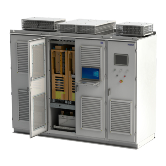
MVC4 control board (User interface) EBX.XX - Optional function expansion board Optional fieldbus board Human Machine Interface DC buss voltage modification board Note: Some parts of the inverter may be different for the MVW01 G2 and G3 lines. MVW01 | 2-12... - Page 25 GENERAL INFORMATION Figure 2.2: MVW01 G3 Panel general view MVW01 | 2-13...
- Page 26 Figure 2.3: MVW01 G3 internal component arrangement (frame size A) ✓ NOTE! For the Rectifier Panel, optionally the cables can entered through the top of the panel.
-
Page 27: Mvw01 Electronic Boards
GENERAL INFORMATION 2.3.3 MVW01 Electronic Boards Table 2.9: MVW01 electronic boards Name Function Panel / Module MVC3 Main Control Control/ A10 PIC2 Power supplies for the electronics, internal use digital inputs and output relays MVC4 User interface control Control/ A12... -
Page 28: Receiving And Storage
Unpacking on page 10-3 If the MVW01 arms are not installed soon in the cabinet, store them in a clean and dry environment (temperature between -20°C and 50°C (-4 and 122 °F) and moisture below 80 %) covered up in order to avoid dust accumulation or water splashing. It is recommended to replace the silica gel every three months. -
Page 29: Mvw01 With 3 Levels (3L)
3 MVW01 WITH 3 LEVELS (3L) The 3 level MVW01 is a variable frequency inverter destined to control medium voltage motors with nominal voltages of 2300 V, 3300 V, 4160 V and 4600 V and with a power range from 540 HP to 30690 HP. In its standard version it uses non-controlled semiconductors (diodes) at the input rectifier stage and controlled semiconductors (HV-IGBTs) to generate the three output phases at the inverter stage, in order to control the... - Page 30 The medium point is necessary to implement the inverter. The inverter is built in a three-level topology (NPC - “neutral point clamped”) using 4 HV-IGBTs (3.3 kV, 4.5 kV or 6.5 kV) and 2 clamping diodes per phase. The complete inverter is assembled inside metallic cabinets with IP21 protection degree (IP41, IP42 optional). Figure 3.2: MVW01 panel (frame size A) MVW01 | 3-2...
-
Page 31: Mechanical Data
MVW01 WITH 3 LEVELS (3L) 3.1 MECHANICAL DATA 3.1.1 Panel Constructive Aspects Figure 3.3: Panel Constructive Aspects The MVW01 line is assembled in panels with the dimensions shown in Table 3.1 on page 3-3 Table 3.1: Mechanical data (dimensions in mm) (mm) -
Page 32: Input Rectifier
The MVW01 is appropriate for operation in industrial environments, with resistance to chemical agents and to corrosion. The cabinet is built with painted steel plates that are processed (cutting, drilling, bending, chemical treatment, painting and finishing) at WEG, assuring the cabinet quality. The inverter parts that are not painted are zinc plated or have another suitable treatment in order to assure their resistance against corrosion. -
Page 33: Inverter Arms
(A1) copper bars. Figure 3.4: MVW01 12-pulse rectifier The rectifier is connected to the DC link located at the rear part of the MVW01 panel. The DC bus supplies the voltage for the three inverter power arms. - Page 34 MVW01 WITH 3 LEVELS (3L) ISOX board DC/DC converters Capacitors IGBTs Laminated busbar Capacitors Figure 3.5: MVW01 Power arm MVW01 | 3-6...
-
Page 35: Control Rack
MVC4 board performs the user interface tasks. Both boards are fed by low voltages coming from the PIC board, which also contains optoisolated digital inputs and relay outputs (220 Vac) for internal MVW01 use. -
Page 36: Available Models
MVW01 WITH 3 LEVELS (3L) 3.5 AVAILABLE MODELS Refer to the Item 2.3.1 Available Models on page 2-5 MVW01 | 3-8... -
Page 37: With 5 Levels (5L)
4 MVW-01 WITH 5 LEVELS (5L) The MVW01 5L line intends to meet the demand at lines with higher voltages and, thus, a specific topology and modulation are used. It uses with the power section structure of H-type bridges connected in star, allowing the inverter operation in 5 levels. -
Page 38: Mechanical Data
Exciter column (for synchronous machines); Output filters; Input filters (AFE); Additional inverter column (AFE); Additional column for cables connection (input and output); Special grounding and safety systems; Special cooling system (air/water); 4.2 AVAILABLE MODELS Item 2.3.1 Available Models on page 2-5 MVW01 | 4-2... -
Page 39: Mvw01C (Compact)
The MVW01C inverter line uses the same topology as the MVW01 line and has as the main feature compact dimensions. In order to achieve such dimensional reduction, all the inverter components are scaled to the power range of this product line. Another feature of this line is that in its standard version the inverter uses an 18 pulse rectifier bridge, which demands a special transformer with 3 secondary windings and 20°... - Page 40 Nominal power according to the inverter power rating considering the input current harmonics. Minimum impedance of 6 %. Shield between primary and secondary windings. Primary voltage according to the available line voltage. Secondary voltages according to the motor nominal voltage and 7.2 kV voltage insulation class. MVW01 | 5-2...
- Page 41 The rectifier is connected to the DC link located at the rear part of the MVW-01C panel, at the inverter compartment. The resistors for the DC bus voltage balancing are mounted together with the rectifier. The DC bus supplies the voltage for the three inverter power arms. MVW01 | 5-3...
- Page 42 +UD, -UD and MP. The connection between inverter arms and the DC link capacitor bank is done by finger contacts and the connection between the DC link and the rectifier is done using cables. Capacitors Figure 5.4: MVW-01C DC link MVW01 | 5-4...
- Page 43 The electric connection of the arms to the power busbars of the DC link is done by means of finger contacts located at the front of the capacitor bank. Connection bars DC/DC converters IGBTs ISOX board Heatsink Laminated busbar Figure 5.5: MVW-01C power arm MVW01 | 5-5...
-
Page 44: Panel Constructive Details
Figure 5.7 on page 5-6 shows the complete panel drawing. The inverter arms are supplied separately inproper packages. Arm dimensions: 260 mm x 607 mm x 522 mm (width x height x depth). Figure 5.7: Dimensions of the MVW-01C panel MVW01 | 5-6... -
Page 45: Available Models
Figure 5.8 on page 5-7 Inverter compartment Rear-view of the BT door Compartment control Rectifier compartment Input bars Output bars U V W Figure 5.8: MVW-01C internal component arrangement 5.2 AVAILABLE MODELS Item 2.3.1 Available Models on page 2-5 MVW01 | 5-7... - Page 46 MVW01C (COMPACT) MVW01 | 5-8...
-
Page 47: Mvw01 Wc (Water Cooled)
The MVW01 WC inverter line uses the same topology as the MVW01 The water cooled MVW01 version is perfect for high demanding and high power applications, such as environments with adverse conditions. It is also the ideal solution for applications where the hot air can not be dissipated and an air conditioner is not a commercially viable solution. -
Page 48: Water Cooled Bridge Rectifier
Bridge rectifier power arms MVW01 WC Figure 6.2: MVW01 WC Panel general view 6.1 WATER COOLED BRIDGE RECTIFIER The medium voltage cables for the input rectifier supply come from the input transformer secondary windings. The transformer configuration and the number of cables depend on the rectifier number of pulses: 12 pulses 6 cables. -
Page 49: Mvw01 Wc Power Arms
Figure 6.3: Water Cooled Rectifier 12 Pulse (example) The rectifier is connected to the DC link located at the rear part of the MVW01 panel, in the inverter column. The DC bus supplies the voltage for the inverter power arms. -
Page 50: Control Rack
Figure 6.4: Water cooled power arm MVW01 6.3 CONTROL RACK The control rack used in the MVW01 WC inverter line has the same functions and uses the same boards of the rack used in the MVW-01 3L and 5L lines. Consult Section 3.4 CONTROL RACK on page 3-7... -
Page 51: Heat Exchanger
MVW01 WC (WATER COOLED) Figure 6.5: RSW80: Primary Hydraulic Circuit (red) and Secondary (blue) 6.4.1 Heat exchanger Both models of the RSWs use 2 different exchangers, the RSW40 uses the brazed model and the RSW80 the plate model. The plates, in the heat exchangers, are widely known for their effectiveness, low cost, great flexibility, and easy maintenance. The secret of this model of heat exchanger is its corrugated plates, which provoke a turbulent flow making the heat exchange extremely efficient and reduces... -
Page 52: Three-Way Valve
The over pressure valve is activated when, due to a system fault, the system pressure exceeds the adjusted value. In these cases, it lets the fluid drain outside the primary circuit, thus preventing the pressure from increasing and damaging any component. The adjustment range is from 0.5 to 10 bar. In the MVW01, it is adjusted to 6 bar. 6.4.8 Automatic Degasser Valve The automatic degasser valve allows the release of the existing air from the primary circuit. -
Page 53: Hydraulic Connections Of The Secondary Circuit (Customer)
MVW01 WC (WATER COOLED) Table 6.1: Coolant Fluid Specifications Primary Circuit Coolant fluid properties Unit Value Hardness °dH < 10 Conductivity µS/cm < 10 mg/l < 10 Chlorine mg/l < 0,1 Iron µm Maximum particle size < 300 For avoiding corrosion, we recommend using CorteC VpCI-649 anticorrosive. See the proportions in Table 6.2 on page 6-7... -
Page 54: Hydraulic Connections Of The Primary Circuit (Inverter)
MVW01 WC (WATER COOLED) 6.5.3 Hydraulic Connections of the Primary Circuit (Inverter) Primary circuit: It is a closed circuit composed of two pumps, a heat exchanger, an expansion tank, flow indicators, flow, temperature, and pressure sensors, besides that, there are valves for diferente purposes. With the regulation valves present in the pipeline, it is possible to adjust the water flow in each power arm, rectifier and reactor heat exchanger. -
Page 55: Mechanical Data
MVW01 WC (WATER COOLED) 6.6 MECHANICAL DATA Figure 6.6: Panel Constructive Aspects The MVW01 WC line is assembled in panels with the dimensions shown in Table 6.5 on page 6-9 Table 6.6 on page 6-9 Table 6.5: Mechanical data 3L (dimensions in mm) -
Page 56: Available Models
MVW01 WC (WATER COOLED) ✓ NOTE! The values shown in Table 6.5 on page 6-9 Table 6.6 on page 6-9 are standard values, however, they may change due to the special characteristics of the product: Input Switchgear; Columns for dynamic braking;... -
Page 57: Output Filters
Depending on the installation conditions, the addition of an output dv/dt filter may be necessary, recommended for drive systems with cable length between 100 (328.08 ft) and 500 m (1640.41 ft), which are designed for application with new WEG motors. For drive systems with cable length greater than 500 m (1640.41 ft), or for driving already existent motors (retrofit applications (motor not prepared for operation with... - Page 58 RLC 02 dV/dt filter 3300V / C 4160V / D 3300V / D 4160V / E 3300V / E > 500m All models Sinusoidal filter Under consultation to WEG (*) Output filters for MVW01 inverters 6000-6900V on request. MVW01 | 7-2...
-
Page 59: Sinusoidal Output Filter
Inverter losses will be higher for operations with a sinusoidal filter. Besides the creation of P0011, parameters P0003 and P0400 were changed in order to adapt the use of the MVW01 with sinusoidal output filter. The description of these parameters can be found in Programming Manual available at www.weg.net... - Page 60 OUTPUT FILTERS MVW01 | 7-4...
-
Page 61: Inverter Parallelism
8.1 STRUCTURE OF THE PARALLEL INVERTER Up to four inverters can be connected in parallel, by means of reactors, in order to extend the power range of the MVW01 line. In this manual the standard inverter (not parallel) is identified as 3L, with two in parallel 3L2, with three in parallel 3L3, and with four in parallel 3L4. -
Page 62: Three Level (3L) Line With Up To Four Set Parallelism (3L4)
Table 8.2 on page 8-2 are valid for the 3300 V and 4160 V lines. More information on the possible MVW-01 voltage and power configurations can be found in the product catalog. MVW01 | 8-2... -
Page 63: Parallelism Of 2 Frame D Or 2 Frame E
P0004 ✓ NOTE! The faults and alarms are entirely described in the programming manual available for download on www.weg.net. The connection between the Control Central/Parallels commands can be performed according to the diagrams of Figure 8.4 on page 8-4 Figure 8.5 on page 8-4... - Page 64 Figure 8.5: Communication between central and parallel racks using FOI4 ✓ NOTE! The connections are made with fiber optic cables, with a length limit of 10 m. More information on panel connections and mechanical dimensions can be found in the inverter electrical project. MVW01 | 8-4...
-
Page 65: Five Level Parallelism Line
H bridge topology, as well as the related parameters. Multipulse rectifier Multipulse rectifier Multipulse rectifier Figure 8.6: Topology of the 6.9 kV line 5 levels parallel The parallelism reactors are magnetically coupled, as shown in the next figure. MVW01 | 8-5... - Page 66 The other mechanical and power options of the 6.9 kV line can be found in the product catalog. The parameters and faults correspondent to the power structure of this line are described in the programming manual available for download on www.weg.net. MVW01 | 8-6...
-
Page 67: Supported Motors
This chapter presents the types of motors compatible with the MVW01 and the respective control strategies. 9.1 INDUCTION MOTOR The MVW01 is a high performance product designed for speed and torque control of three-phase induction motors. Motors of this type can be controlled by the following control strategies: Scalar control (V/f);... - Page 68 Bit 0 Zero Par. Zero Parity Figure 9.2: Example of Clock specification and data transfer to the absolute encoder Table 9.1: Encoder recommendations for use in the MVW01 Manufacturer Encoder Model Quantity of bits Zero bit Parity bit Leine Linde...
- Page 69 Terra Figure 9.4: Connection diagram with the MVC3 and FOI3 boards CTRL Com (Common) +5V (+Output) -Vi (-Input) -15V (-Aux) +Vi (+Input) Com (Common) +15V (+Aux) N3_CHA N2_CHA N3_CHB N2_CHB 12119560 (GBR R02) Figure 9.5: RSSI Board MVW01 | 9-3...
-
Page 70: Field Set (Dc With Brushes)
Current reference input AC-DC: 0 to 10 V (CA-CC 5 V = 1 PU, observe P0462); Feedback of the output current for the MVW01 : 0 to 10 V (MVW01 5 V = 1 PU, observe P0462 and P0744). ✓... -
Page 71: Installation, Connection And Energization
This chapter describes the electrical and mechanical installation procedures for the MVW01. The presented guidance and suggestions must be followed in order to assure the proper inverter operation. WARNING! The handling of the MVW01 and its mechanical and electrical installation must be carried out by persons trained and qualified by WEG. WARNING! STORAGE OF THE MVW01 PANEL AND ARMS: After receiving the equipment, remove the plastic film in order to prevent moisture condensation. -
Page 72: Handling Recommendations
Pollution degree: 2 (according to IEC/UL standards) with non-conductive pollution. Condensation shall not originate conduction through the accumulated residues. The medium voltage inverter MVW01 is supplied in form of a panel, whose dimensions are presented in Table 3.1 on page 3-3 . -
Page 73: Moving
10.1.5 Unpacking Use proper tools to unpack the MVW01 panel and its arms. During this process, make sure that all the items listed in the documentation that comes with the product are present and in perfect conditions. Contact your local WEG representative in case of any irregularity. - Page 74 INSTALLATION, CONNECTION AND ENERGIZATION Timber package Ribbon bow Power arm Styrofoam pad Pallet Figure 10.2: Standard power arm with package MVW01 | 10-4...
-
Page 75: Positioning/Mounting
Figure 10.3: Compact power arm with package 10.1.6 Positioning/Mounting The MVW01 panel must be placed on a flat leveled surface, thus avoiding mechanical instability, door misalignment, among other problems. WARNING! Some MVW01 models are sectioned for transport purposes. The sectioned parts must be properly coupled during start-up. -
Page 76: Power Arm Insertion
Figure 10.4: Anchoring the MVW01 panel to the floor ✓ NOTE! Recommendations for anchoring the panel may vary for the several MVW01 models. For more information refer to the specific project documentation. 10.1.7 Power Arm Insertion Figure 10.5: Power Arm... - Page 77 INSTALLATION, CONNECTION AND ENERGIZATION Figure 10.6: Power arm insertion/extraction/movement trolley The power arm insertion must be performed with the help of the transport trolley (WEG part number 11136572), as shown in Figure 10.6 on page 10-7 and according to the following procedure.
-
Page 78: Power Arm Electric And Fiber Optic Connections
After inserting the power arms (U, V and W phases) connect the fiber optic cables and the supply cables according to the labels presented on the arms and on the cables. The identifications of the cables are presented in the Table 10.2 on page 10-9 Table 10.3 on page 10-9 MVW01 | 10-8... - Page 79 Hold the cables only at their connectors when inserting or removing them, and never apply pressure or tensile force on the fiber. In order to extract the power arms follow the procedures described in the previous sections in reverse order. MVW01 | 10-9...
-
Page 80: Insertion Of The Mvw01C Power Arms
10.1.9 Insertion of the MVW01C Power Arms Figure 10.9: Power arms inserted in the MVW01C The power arm insertion must be performed with the help of the transport trolley (WEG part number 11136572), and according to the following procedure. ✓... - Page 81 7. Holding on both power arm handles, push it observing the alignment of the wheels with the base in the panel. 8. The arms must be inserted to the point that the locking pin engages. Observe the label about the insertion end, as shown in picture 5. MVW01 | 10-11...
- Page 82 2. In order to connect the ISOX fiber optic cables and the power supply cable, it is necessary to remove the protective acrylic cover. 3. Connect the optic fibers OSA, OSB, and TEMP, and the power supply cable XC1, according to the picture 2. MVW01 | 10-12...
-
Page 83: Electrical Installation
Refer to the cubicle (main circuit breaker) and transformer documentation, strictly following all the recommendations. The power cables that connect the input, transformer secondary windings to the MVW01 rectifier column and those that connect the inverter column to the medium voltage motor (Figure 10.10 on page 10-15... - Page 84 The cable cross sections/gauges presented in the Table 10.7 on page 10-14 are only orientative. In order to size the cables correctly the installation conditions, the applicable standards and regulations, and the maximum allowed voltage drop must be considered. MVW01 | 10-14...
- Page 85 Use proper terminations for the power connections as well as for the shield connections to the ground bar. Tighten the connections with the appropriate torque. Table 10.9: Power connections cable lugs and tightening torque Cable Lug Torque [Nm] ±20 % Identification Column Rectifier Inverter Shields Rectifier and Inverter MVW01 | 10-15...
-
Page 86: Input Circuit Breaker
The MVW01 operates the input circuit breaker. This circuit breaker must have minimum voltage, closing and opening coils. The power supply for the circuit breaker circuits comes from the MVW01. The following signals, provided by the circuit breaker, are necessary for its operation: READY ( Ready), ON (On), OFF (Off) e TRIP (Trip). -
Page 87: Low Voltage Auxiliary Supply
(élément Item 10.3.5 Safe De- energization Instructions on page 10-20 ✓ NOTE! It is recommended that the MVW01 Kirk key is interlocked with the ring welded to the key of the input cubicle. Transformer Inverter VADE1 Shielding... -
Page 88: Energization, Start-Up And Safe De-Energization
1. Check if all the power, grounding and control connections are correct and tightened. 2. Clean the inverter internally, remove all packing material and installation residues from within the MVW01 cabinets. 3. Check all motor connections and verify whether its voltage, current and frequency match the inverter specifications. -
Page 89: Initial Power-Up (Parameter Settings)
This section describes the inverter start-up with keypad operation. The considered control mode is V/F 60 Hz. DANGER! High voltages may be present even after the power supply disconnection. The following sequence is valid for the standard MVW01 inverter. The inverter should have already been installed and programmed, according to Chapter 10 INSTALLATION, CONNEC-... -
Page 90: Safe De-Energization Instructions
F0014 - Input circuit breaker closing failure. F0017 - Input circuit breaker not ready. F0020 - Pre-Charge Fault. Refer to these error (alarm/fault) descriptions in the MVW01 Programming Manual. ✓ NOTE! The last speed reference value, set via the and keys , is saved in the memory (P0120 = 1). - Page 91 S’il n’était pas possible de suivre la décharge des condensateurs de liaison CC avec le paramètre P0004 et les lampes à néon de la carte HVM en raison d’un dysfonctionnement ou une mise hors tension préalable, suivez les instructions 5) jusqu’à 8) et attendez 10 minutes supplémentaires. MVW01 | 10-21...
- Page 92 INSTALLATION, CONNECTION AND ENERGIZATION MVW01 | 10-22...
-
Page 93: Optional Accessories And Boards
”The signal (analog inputs/outputs) and control (digital inputs/outputs and relay outputs) connections are made at the following terminal strips on the MVC4 control board (refer to the Figure 11.1 on page 11-1 ).” XC1A : digital signals. XC1B : analog signals. XC1C : relay outputs. Figure 11.1: MVC4 - Customer connectors MVW01 | 11-1... -
Page 94: Digital Inputs
- Minimum high level: 18 Vdc - Maximum low level: 3 Vdc - Maximum voltage: 30 Vdc - Input current: 11 mA @ 24 Vdc Active low Active high Connector Signal Connector Signal Figure 11.2: Description of the XC1A connector: digital inputs MVW01 | 11-2... -
Page 95: Analog Inputs And Outputs
ON - (0 to 20) mA / (4 to 20) mA OFF - (0 to 20) mA P0259 = Real Speed S4.A ON (4 to 20) mA OFF - (0 to 20) mA P0261 = Output Cur S5.A ON (4 to 20) mA MVW01 | 11-3... -
Page 96: Relay Output
5. Relays, contactors, solenoids or electromagnetic braking coils installed near inverters can generate interference in the control circuit; In order to eliminate this interference, connect RC suppressors in parallel with the coils of AC relays. Connect a free-wheeling diode in case of DC relays/coils; MVW01 | 11-4... -
Page 97: Function Expansion Boards
OPTIONAL ACCESSORIES AND BOARDS 6. When an external keypad (HMI) is used (for further information, refer to the programming manual available for download on www.weg.net), separate the cable that connects the keypad to the inverter from other cables of the installation, keeping a minimum distance of 10 cm (4 in) between them. - Page 98 ENCODER CONNECTION: refer to Section 11.3 INCREMENTAL ENCODER on page 11-14 INSTALLATION The EBA board is installed directly on the MVC4 control board, secured with spacers and connected via terminal blocks XC11 (24 V) and XC3. Mounting instructions: MVW01 | 11-6...
- Page 99 5. Secure the board to the 2 metallic spacers with the 2 provided bolts; 6. Plug the XC11 connector of the EBA board to the XC11 connector on the MVC4 control board. Figure 11.6: Position of the adjustment elements - EBA board MVW01 | 11-7...
- Page 100 Without termination With termination (120 Ω) Table 11.8: Trimpot settings - EBA card Trimpot Function OFF (Factory Default) AO3 - Offset P0255 = Real Speed AO3 - Gain AO4 - Offset P0257 = Output Cur AO4 - Gain MVW01 | 11-8...
-
Page 101: Ebb (Expansion Board B - I/O)
The use of the RS-485 serial interface does not allow the use of the standard RS-232 input of the MVC4 board. They cannot be used simultaneously. AO1’/AO2’ analog outputs are the same AO1/AO2 outputs on the MVC4 control board. MVW01 | 11-9... - Page 102 The analog input AI3 and the analog outputs AO1’ and AO2’ isolation has the purpose of interrupting ground loops. Do not connect them to high potentials. ENCODER CONNECTION: refer to Section 11.3 INCREMENTAL ENCODER on page 11-14 MVW01 | 11-10...
- Page 103 6. Fit the XC11 connector on the EBB board to the XC11 connector on the control board (MVC4). Figure 11.9: Position of the adjustment elements - EBA board EBB board MVC4 board Figure 11.10: Procedure to install the EBB board MVW01 | 11-11...
-
Page 104: Plc2
The external signal and control connection must be fitted to XC5 (EBB) observing the same recommendations as those for the connection of the MVC4 control board (see Section 11.1 MVC4 SIGNAL AND CONTROL CONNECTIONS on page 11-1 11.2.3 PLC2 ✓ NOTE! For further information, see the specific manual for the PLC2 board. MVW01 | 11-12... - Page 105 250 Vac, 3 A COM DO Common of the DO4...DO6 digital outputs Bidirectional opto-isolated digital outputs 48 Vdc, 500 mA COM DI Common of the DI1...DI9 inputs Bidirectional isolated digital inputs 15-30 Vdc, 11 mA @ 24 Vdc MVW01 | 11-13...
-
Page 106: Incremental Encoder
Applications that require more speed or positioning accuracy, a speed feedback of the motor shaft by means of incremental encoder is required. The connection to the inverter is made through the XC9 connector (DB9) on the EBA function expansion board, or XC9 on EBB, or XC10 on EBC. MVW01 | 11-14... -
Page 107: Eba/Ebb Boards
During start-up, it is necessary to program parameter P0202 (Control Type) = 4 (Encoder) to operate with speed feedback by incremental encoder. For further details on vector control, see the programming manual available for download on www.weg.net. The function expansion boards EBA and EBB have an encoder signal repeater, isolated and externally powered. -
Page 108: Ebc1 Board
XC3 connector; 3. Press the center of the board (near XC3) until the connector is completely inserted; 4. Secure the board to the 2 metallic spacers with the 2 provided bolts. MVW01 | 11-16... - Page 109 OPTIONAL ACCESSORIES AND BOARDS Figure 11.16: Position of the setting elements - EBC1 board. Figure 11.17: Procedure to install the EBC1 board. MVW01 | 11-17...
- Page 110 During start-up, it is necessary to program parameter P0202 (Control Type) = 4 (Encoder) to operate with speed feedback by incremental encoder. For further details on vector control, see the programming manual available for download on www.weg.net. MVW01 | 11-18...
-
Page 111: Short Ups Module
11.4 SHORT UPS MODULE The Short UPS module is an accessory that provides autonomy of approximately 500 ms in case of failure of the MVW01 inverter auxiliary power supply. After the occurrence of the auxiliary power supply failure, the inverter remains operational, without faults, during 500 ms. -
Page 112: Mvc3 Control Board Connections
P263 = 0 (DI1 Digital input); P264 = 0 (DI2 Digital input); P265 = 4 (DI3 Digital input); P266 = 6 (DI4 Digital input); P297 = 10 kHz (Switching frequency). 11.5 MVC3 CONTROL BOARD CONNECTIONS Figure 11.21: MVC3 board connections MVW01 | 11-20... - Page 113 Function (Factory default) Specification AI2- Differential, 11-bit resolution P0744 (AI2 MVC3 Funct.): 0 (Not Used) AI2+ Impedance: 400 kΩ (-10 V to 10 V) WARNING! The I/Os described above are not isolated. Their utilization must be with galvanic isolators. MVW01 | 11-21...
- Page 114 OPTIONAL ACCESSORIES AND BOARDS MVW01 | 11-22...
-
Page 115: Special Functions
Auxiliary (s) inverter (s): On the auxiliary inverter(s), it is necessary to parameterize an analog input of MVC3 board to receive the torque reference sent by the main inverter. P0740 (Analog Input 1 Function) = 1 (Torque reference). MVW01 | 12-1... -
Page 116: Limitation Of The Torque Current - Operation In Vector Mode
P0236 (Input AI1 Offset) = 5.0 %. P0133 (Minimum Speed Reference) = set according to the application. P0134 (Maximum Speed Reference) = set according to the application; it must be 5 % above the maximum limit of the main inverter. MVW01 | 12-2... -
Page 117: Negative Slip - Operation In Scalar Mode
The description given of the ways to implement the load sharing function intends neither to approach all possibilities of implementation, nor to detail all the aspects involved. The definition of the best implementation mode for a certain application, as well as the optimal adjustment of each mode must be defined by WEG engineering and application teams. MVW01 | 12-3... -
Page 118: Synchronous Transfer Or Synchronous Bypass Function
2 ms after the circuit breaker/contactor closes. The effect of a very long time on P0631 generates an increase in the inverter current, which can reach the tripping value of the overcurrent fault F0070. In Sensorless mode, the inverter must be disabled before opening the inverter output contactor/breaker. MVW01 | 12-4... -
Page 119: Important Signals For Analog Outputs
P0631 – Very long delay in the ”Fast Disable” actuation, causing the inverter to remain in parallel with the grid for a very long period. No Voltage on the Motor (During Transfer) P0631 – A very short delay in the ”Fast Disable” actuation, causes the inverter to be disabled before the bypass circuit breaker has completed closing its contacts. MVW01 | 12-5... -
Page 120: Operating Sequency
SPECIAL FUNCTIONS 12.2.4 Operating Sequency Figure 12.6 on page 12-6 describes all the operating sequence of the signals involved in the synchronous transfer process. Figure 12.6: General operation scheme of the synchronous bypass function MVW01 | 12-6... -
Page 121: Safety Stop Function
Since this is a safety function, the implementation is performed through a relay that presents actuation redundancy and simultaneity in the activation mode. Such redundancy is used both in the disconnection of the supply and in the information to the control and feedback to the client. MVW01 | 12-7... - Page 122 The system leaves the safety stop function 100 ms after the signal of digital input DI15 is removed, and the inverter begins to monitor all the faults again, accept commands of enable PWM and reset of alarm A165. MVW01 | 12-8...
-
Page 123: Diagnostics And Troubleshooting
WEG l’Assistance Technique. The MVW01 inverter has been designed and tested to have a long, failure-free, operation life. The preventive maintenance helps early iden- tification of possible future failures, extending the useful life of the equipment, increasing the mean time between failures and reducing the equipment downtime. - Page 124 DIAGNOSTICS AND TROUBLESHOOTING DANGER! Seul un personnel formé, ayant les qualifications adéquates et familiarisé avec le the MVW01 et l’équipement associé peut planifier et mettre en oeuvre l’installation, le démarrage, l’utilisation et la maintenance de cet équipement. Ce personnel doit suivre toutes les instructions de sécurité décrites dans ce mode d’emploi et/ou définies par la règlementation locale.
-
Page 125: Preventive Maintenance With Complete Stop/De-Energization
This equipment has high voltages that may cause electric shocks. Only people with properly qualified and familiar with the MVW01 Inverter and associated equipment must plan or service this equipment. In order to avoid the risk of shock, follow all the safety procedures required for servicing energized equipment. - Page 126 Cet équipement a des tensions élevées pouvant causer des décharges électriques. Seul un personnel qualifié et familier avec l’onduleur de fréquence the MVW01 et ses équipements associés doit préparer et mettre en oeuvre l’entretien de cet équipement. Afin d’éviter un risque de décharge électrique, suivez toutes les procédures de sécurité requises pour l’entretien courant sur un équipement sous tension.
-
Page 127: Safe De-Energization Instructions
S’il n’était pas possible de suivre la décharge des condensateurs de liaison CC avec le paramètre P004 et les lampes à néon de la carte HVM en raison d’un dysfonctionnement ou une mise hors tension préalable, suivez les instructions 5 jusqu’à 8 et attendez 10 minutes supplémentaires. MVW01 | 13-5... -
Page 128: General Warranty Conditions For Mvw-01 Frequency Inverters Mvw01
13.4 GENERAL WARRANTY CONDITIONS FOR MVW-01 FREQUENCY INVERTERS MVW01 Weg Automação S.A, located at Av. Pref. Waldemar Grubba, 3000 in the city of Jaraguá do Sul – SC, provides warranty for defects in material and workmanship for WEG frequency inverters under the following conditions: 1. - Page 130 WEG Drives & Controls - Automação LTDA. Jaraguá do Sul – SC – Brazil Phone 55 (47) 3276-4000 – Fax 55 (47) 3276-4020 São Paulo – SP – Brazil Phone 55 (11) 5053-2300 – Fax 55 (11) 5052-4212 automacao@weg.net 10192955...
Need help?
Do you have a question about the MVW01 and is the answer not in the manual?
Questions and answers