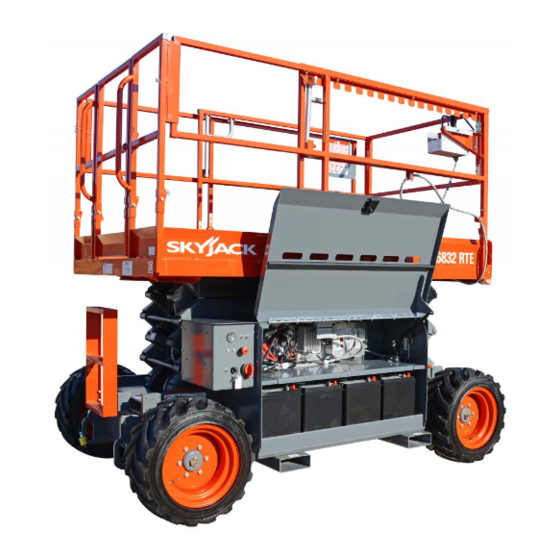
Skyjack SJ6832 RTE Series Operating Manual
Rough terrain scissors
Hide thumbs
Also See for SJ6832 RTE Series:
- Service manual (163 pages) ,
- Operation manual (112 pages) ,
- Operating manual (96 pages)

Related Manuals for Skyjack SJ6832 RTE Series


Summary of Contents for Skyjack SJ6832 RTE Series
- Page 1 OPERATING MANUAL (CE) ROUGH TERRAIN SCISSORS MODEL SJ6832 RTE 194392AE-A January 2018...
- Page 2 This manual is based on Serial Number(s): SJ6832 RTE 37 300 175 & Above Please refer to the website (www.skyjack.com) for older Serial Numbers. Skyjack Service Center Parts & Service (Europe) Unit 1 Maes Y Clawdd 3451 Swenson Ave. St. Charles,...
- Page 3 The Safety Alert Symbol identifies important safety messages on aerial platform, safety This Safety Alert Symbol means attention! signs in manuals or elsewhere. When you see this symbol, be alert to the possibility of Become alert! Your safety is involved. personal injury or death.
- Page 4 Maximum Platform Capacities (Evenly Distributed) ................68 Table 4.5 Floor Loading Pressure ........................69 Table 4.6 Operator’s Daily Inspection Checklist .....................71 Table 4.7 EC Declaration of Conformity ......................72 Section 5 - Labels ............................73 Section 6 - Skyjack Features .........................97 Rough Terrain Electric Scissors Page 4 December 2007...
- Page 5 SKYJACK warrants each new SJRT Compact Electric Series work platform to be free of defective parts and workmanship for the first 24 months. Any defective part will be replaced or repaired by your local SKYJACK dealer at no charge for parts or labor. Contact the SKYJACK Service Department for warranty statement extensions or exclusions.
- Page 6 Common sense dictates the use of protective clothing when working on or near machinery. Use appropriate safety devices to protect your eyes, ears, hands, feet and body. Any modifications from the original design are strictly forbidden without written permission from SKYJACK. Electrocution Hazard This aerial platform is not electrically insulated.
- Page 7 Section 1 - About Your Aerial Platform Safety Rules Safety Precautions Know and understand the safety precautions before going on to next section. WARNING • DO NOT increase the lateral Failure to heed the following safety surface area of the platform. precautions could result in tip over, Increasing the area exposed falling, crushing, or other hazards leading...
- Page 8 Safety Rules Section 1 - About Your Aerial Platform Safety Precautions (Continued) Know and understand the safety precautions before going on to next section. operate on surfaces not capable of • AVOID overhead obstructions. • DO NOT holding the weight of the aerial platform including aware overhead the rated load, e.g.
- Page 9 • DO NOT place materials on the guardrails or materials that exceed the confines of the guardrails unless approved by Skyjack. • DO NOT use the aerial platform without guardrails, locking pins • STUNT driving and horseplay are prohibited.
- Page 10 If additional fall protection is required, platform that: by an employer or the authority having jurisdiction, Skyjack recommends the use of a fall restraint • does not appear to be working system to keep an occupant within the confines of properly.
- Page 11 Section 2- Familiarization SJRT Series 2.1 Familiarization of SJ68RTE Series WARNING Aerial Platform Familiarization should be given only to individuals who are QUALIFIED and TRAINED to operate an aerial platform. Do not operate this aerial platform without proper authorization and training. Failure to avoid this hazard could result in death or serious injury.
- Page 12 Control Functions Section 2 - Familiarization 2.2 Component Identification 2.2-4 Load Sensing System This system is a safety device that prevents any normal The following descriptions are for identification, movement of the aerial platform from a stationary explanation and locating purposes only. working condition after the rated load is reached and exceeded.
- Page 13 Section 2 - Familiarization Control Functions 2.2-5 Emergency Lowering System 2.2-7 Free-wheeling Valve The emergency lowering system allows platform lowering in the event of an emergency or an electrical system failure. Refer to Section 2.6 for the emergency lowering procedure. The system contains the following controls: Figure 2-3.
- Page 14 Control Functions Section 2 - Familiarization 2.2-8 Base Control Console Power Indicator Light - When the emergency The control console is located on the left side of the stop button on the base control console and on battery/electrical compartment. It contains the following the platform control console are both pulled out, controls: this light glows.
- Page 15 Section 2 - Familiarization Control Functions 2.2-9 Platform Control Console Horn Push Button - This “ ” push button This removable control console is mounted at the right sounds an automotive-type horn. front of the platform. It contains the following controls: Inclined Drive/Level Drive Switch - This switch selects “...
- Page 16 Visual & Maintenance Inspection Section 2 - Familiarization Platform Control Console Scissor Assembly Platform Assembly Limit Switch Limit Switch Outriggers Outriggers Base 2.3 Visual & Daily Maintenance Inspections 2.3-2 Electrical Maintaining the electrical components is essential to Begin the visual and daily maintenance inspections good performance and service life of the aerial platform.
- Page 17 Section 2 - Familiarization Visual & Maintenance Inspection Base Control Console Tilt Sensor Main Power Disconnect Switch Battery 2.3-5 Battery/Electrical Compartment WARNING Ensure compartment latch is secure and Battery acid is extremely corrosive - Wear in proper working order. proper eye and facial protection as well as •...
- Page 18 Visual & Maintenance Inspection Section 2 - Familiarization Gear Type Hydraulic Flow Divider Oil Filter Oil Level Gauge Main Manifold Hydraulic Tank • Hydraulic Pump • Main Manifold Ensure there are no loose or missing Ensure all fittings and hoses are properly tightened and there is no evidence of parts and there is no visible damage.
- Page 19 Section 2 - Familiarization Visual & Maintenance Inspection Fall Protection Manuals Anchorage Platform Railing Platform Control Console AC Outlet Platform Assembly 2.3-7 Platform Assembly • Manuals Ensure a copy of operating manual and CE certificate are enclosed in manual storage WARNING box.
- Page 20 Visual & Maintenance Inspection Section 2 - Familiarization Maintenance Lift Cylinder Support Limit Switch Scissor Bumper Scissor Guard Roller Scissor Assembly 2.3-8 Lifting Mechanism • Rollers Ensure rollers are secure and there is no 1. Raise the platform (refer to Section 3.8-2) until visible damage.
- Page 21 Therefore, replace tires only with the exact Skyjack- • Wheel/Tire Assembly approved type. Failure to operate with The aerial platform is equipped with foam-filled matched approved tires in good condition tires.
- Page 22 Visual & Maintenance Inspection Section 2 - Familiarization Overhead View Steer Cylinder Assembly Base Weldment Splitter Manifold Wheel/Tire Assembly Tie Rod Emergency Lowering Access Rod Steer Cylinder Assembly • Ladder Ensure steer cylinder assembly is Ensure there are no loose or missing properly secured, there are no loose parts and there is no visible damage.
- Page 23 Section 2 - Familiarization Function Tests Emergency Stop Button Platform/Off/Base Key Switch Main Power Disconnect Switch 2.4 Function Tests 2.4-2 Base Control Console Function tests are designed to discover any malfunctions before aerial platform is put into service. The operator WARNING must understand and follow step-by-step instructions Ensure that you maintain three points of...
- Page 24 Function Tests Section 2 - Familiarization Emergency Stop Button Free-wheeling Platform/Off/Base Key Valve Switch Brake Hand Pump Brake Auto Reset Valve Emergency Lowering Valve Main Power Disconnect Switch Base Control Console Main Manifold • Test Platform/Off/Base Key Switch • Test Emergency Stop 1.
- Page 25 Section 2 - Familiarization Function Tests Lift/Drive/Steer Enable Trigger Switch Lift/Drive/Steer Rocker Switch Controller Free-wheeling Valve Brake Auto Reset Valve Brake Hand Pump Inclined Drive/Level Drive Switch Emergency Lowering Lift/Drive Switch Valve Horn Pushbutton Emergency Stop Button Main Manifold • Test Emergency Lowering •...
- Page 26 Function Tests Section 2 - Familiarization Lift/Drive/Steer Enable Rocker Switch Trigger Switch Lift/Drive/Steer Controller Inclined Drive/Level Drive Switch Emergency Stop Button Lift/Drive Switch Horn Pushbutton • Test Platform Raising/Lowering WARNING WARNING Ensure that you maintain three points of contact when using the ladder to mount/ Be aware of overhead obstructions dismount platform.
- Page 27 Section 2 - Familiarization Function Tests Lift/Drive/Steer Enable Rocker Switch Trigger Switch Lift/Drive/Steer Controller Inclined Drive/Level Drive Switch Emergency Stop Button Lift/Drive Switch Horn Pushbutton • Test Driving • Test Elevated Drive Speed 1. Ensure path of intended motion is clear. WARNING Be aware of overhead obstructions 2.
- Page 28 Function Tests Section 2 - Familiarization Lift/Drive/Steer Enable Rocker Switch Trigger Switch Lift/Drive/Steer Controller Inclined Drive/Level Drive Switch Emergency Stop Button Lift/Drive Switch Horn Pushbutton • Test Brakes • Test Horn 1. Push “ ” horn pushbutton. WARNING Result: Horn should sound. Brakes will engage instantly when you release the controller handle, causing aerial platform to stop immediately.
- Page 29 Section 2 - Familiarization Function Tests Lift/Drive/Steer Enable Rocker Switch Trigger Switch Lift/Drive/Steer Controller Inclined Drive/Level Drive Switch Emergency Stop Button Lift/Drive Switch Horn Pushbutton • Test Load Sensing Activate and hold “ ” enable trigger switch. WARNING Pull controller handle and attempt Be aware of overhead obstructions to lower the platform.
- Page 30 Function Tests Section 2 - Familiarization Left-Rear Left-Front Outrigger Control Console Platform Control Console Right-Rear Right-Front • Test Hydraulic Outriggers (If Equipped) 7. Drive the aerial platform to maximum (For Hydraulic Outrigger Operation, refer to speed. Section 3.8-9) Result: Aerial platform drives at high speed.
- Page 31 Section 2 - Familiarization Function Tests Left-Rear Left-Front Outrigger Control Console Platform Control Console Right-Rear Right-Front Attempt to partially extend Right-Rear With Right-Rear Outrigger partially Outrigger (approximately 4”). extended, attempt to lift the platform. Result: Outrigger will not extend. Result: Lift function will not operate. Attempt to partially extend Left-Rear With Left-Rear Outrigger partially Outrigger (approximately 4”).
- Page 32 Function Tests Section 2 - Familiarization Left-Rear Left-Front Outrigger Control Console Platform Control Console Right-Rear Right-Front Attempt to lift the platform 1 foot. 18. Extend all four outriggers until all tires are Result: Lift function will not operate. off the ground and the aerial platform is levelled.
- Page 33 Section 2 - Familiarization Procedures 2.5 Winching and Towing Procedure Free-wheeling Valve - Turning the valve knob counterclockwise (item 1) to a fully opened This section provides the operator with the Winching position allows fluid to flow through the wheel and Towing procedure, which includes instructions on motors, thus providing “free-wheeling”.
- Page 34 Procedures Section 2 - Familiarization 2.6 Emergency Lowering Procedure Remove wheel chocks or blocks, then push, winch or tow aerial platform to desired location. This section guides the operator on how to use emergency lowering system. This system allows platform lowering in the event of an emergency. WARNING Brakes must be reengaged immediately WARNING...
- Page 35 NOTE Refer to Skyjack’s website www.skyjack.com • The operator must be familiar with employer’s work for latest service bulletins prior to performing rules and related government regulations and be frequent or yearly inspections.
- Page 36 Section 3 - Operation 3.2 Major Components Manual Storage Box Entry Gate Platform Control Console Main Platform Extension Lifting Platform Mechanism Maintenance Battery/Electrical Support Compartment Outriggers Base SKYJACK Model SJ 6832RTE Aerial Platform Rough Terrain Electric Scissors Page 36 December 2007...
- Page 37 Section 3 - Operation Major Assemblies 3.3 Major Assemblies 3.4 Serial Number Nameplate The aerial platform consists of three major assemblies: The serial number nameplate, located at the rear of the base, lifting mechanism and platform. aerial platform, lists the following: •...
- Page 38 Component Identification Section 3 - Operation 3.5 Component Identification WARNING The following descriptions are for identification, The maintenance support must be used explanation and locating purposes only. when inspection and/or maintenance or repairs are to be performed within the 3.5-1 Manual Storage Box lifting mechanism.
- Page 39 Section 3 - Operation Component Identification 3.5-3 Folding Guardrail System WARNING This system, when folded down, reduces the height Before operating this aerial platform of the retracted aerial platform for transporting and check the guardrail system for loose traveling through doorways only. Refer to Section 3.9 or missing locking pins.
- Page 40 Component Identification (Special Options) Section 3 - Operation 3.6 Component Identification Leveling Indicator Light - This light illuminates to display the status of the outriggers when the (Optional Equipment/Attachments) auto and manual level functions are in use. The This section describes the components that are optional indicator light has the following states: to aerial platforms.
- Page 41 Section 3 - Operation Component Identification (Special Options) 3.6-2a Hybrid Power Pack (HPP) - Gasoline (If Equipped) : Red LED light indicates low oil level. The sole purpose of this HPP is to charge the battery. It runs either automatically or manually. In automatic : In case of power overload, push to reset mode, the HPP automatically starts when the battery power circuit breaker.
- Page 42 Component Identification (Special Options) Section 3 - Operation HPP Air Inflow On/ Off Switch HPP On/Off Switch Figure 3-10. Platform Control Console Figure 3-8. HPP Air Inflow On/Off Switch Manual Mode Ensure main power disconnect is in “ ”on position Return HPP to operating position and insert and base “...
- Page 43 Section 3 - Operation Component Identification (Special Options) 3.6-2b Hybrid Power Pack (HPP) - Diesel Turn Off (From Base Control Console) On base control console, turn HPP on/off switch (If Equipped) to “ ” off position. The purpose of this HPP is to charge the battery and provide power to platform.
- Page 44 Component Identification (Special Options) Section 3 - Operation Automatic Mode Turn HPP automatic/manual switch to “M” (manual) position. Ensure main power disconnect is in “ ” on position and base “ ” emergency stop button is pulled On platform control console, ensure platform out.
- Page 45 Section 3 - Operation Component Identification (Special Options) HPP Refueling Procedure - Gasoline Protection of Environment from Chemical Dangers This section provides the operator with the procedure on how to refuel the HPP with gasoline. WARNING Gasoline and engine oil are chemicals, WARNING which can contaminate the environment.
- Page 46 Component Identification (Special Options) Section 3 - Operation HPP Refueling Procedure - Diesel Protection of Environment from Chemical Dangers This section provides the operator with the procedure on how to refuel the HPP with diesel. WARNING Diesel and engine oil are chemicals, WARNING which can contaminate the environment.
- Page 47 Section 3 - Operation Operator’s Responsibility 3.7 Operator’s Responsibility Repairs to the aerial platform may only be made by a qualified service technician. After repairs are completed, It is the responsibility of the operator, prior to each work the operator must perform visual and daily maintenance shift, to perform the following: inspections &...
- Page 48 Start Operation Section 3 - Operation 3.8 Start Operation WARNING Carefully read and completely understand the operating An operator should not use any aerial manual and all warnings and instruction labels (refer to platform that: Section 5 - Labels) on the aerial platform. •...
- Page 49 Section 3 - Operation Start Operation 3.8-1 To Activate Base Control Console 3.8-2 To Raise or Lower Platform Using Base Control Console WARNING WARNING Ensure that you maintain three points of contact when using the ladder to mount/ Be aware of overhead obstructions or dismount platform.
- Page 50 Start Operation Section 3 - Operation 3.8-3 To Activate Platform Control Console 3.8-4 To Raise or Lower Platform Using Platform Control Console Turn main power disconnect switch to “ ”on position. WARNING Be aware of overhead obstructions or On the base control console, pull out the “ ”...
- Page 51 Section 3 - Operation Start Operation 3.8-5 To Drive Forward or Backward 3.8-6 To Steer Activate platform control console (refer to WARNING Section 3.8-3). Be aware of blind spots when operating the aerial platform. On the platform control console, turn lift/drive switch to “...
- Page 52 Start Operation Section 3 - Operation 3.8-7 To Select Drive Torque 3.8-8 To Extend or Retract Manual Extension Platform High Torque: Select high torque when climbing grades, traveling on rough terrain or when loading or unloading aerial platform. To activate high torque, select torque switch to “...
- Page 53 Section 3 - Operation Start Operation 3.8-9 Hydraulic Outriggers (If Equipped) Ensure each outrigger pad is in firm contact over These devices are mounted to four corners of the base. its entire surface area, with a suitable supporting When properly positioned, they increase the stability of surface! Make adjustments if necessary using the aerial platform.
- Page 54 Start Operation Section 3 - Operation 3.8-10 Shutdown Procedure Completely lower the platform. On the platform control console, push in “ ” emergency stop button. WARNING Ensure that you maintain three points of contact when using the ladder to mount/ dismount platform.
- Page 55 Section 3 - Operation Guardrail Folding Procedure 3.9 Guardrail Folding Procedure To fold the guardrail system down: When folded down, the folding guardrail system reduces Ensure aerial platform is on level ground. the height of the retracted aerial platform for transporting only.
- Page 56 Guardrail Folding Procedure Section 3 - Operation Remove all the locking pins on the left side Use the ladder of aerial platform to access guardrail and fold it down. platform. WARNING With the gate closed, remove all the locking Any lowered guardrail will create a fall pins on the entrance side guardrail and fold the hazard.
- Page 57 The transport vehicle must be parked on a level surface and must be secured to prevent rolling while aerial platform is being loaded/unloaded. 3.10-1 Lifting When it is necessary to lift the Skyjack aerial platform the following conditions must be met: • The platform must be fully lowered.
- Page 58 Loading/Unloading Section 3 - Operation NOTE Lift with forks in designated forklift lifting locations as illustrated in Figure 3-19. Forklift Lifting Locations (aerial Forklift Lifting Locations platforms with no outriggers) Figure 3-19. Forklift Lifting Locations 3.10-2 Driving When driving the aerial platform: •...
- Page 59 Section 3 - Operation Moving the Aerial Platform Through a Doorway 3.11 Moving the Aerial Platform Through a Ensure there are no personnel in the intended path of travel. Doorway Notify those around the pathway that you will be WARNING moving the aerial platform.
- Page 60 Moving the Aerial Platform Through a Doorway Section 3 - Operation Return guardrails to upright position if folded. (Refer Section 3.9 for guardrail folding procedure.) WARNING Before operating this aerial platform check the guardrail system for loose or missing locking pins. The guardrail system must be upright and all pins must be locked in place.
- Page 61 Section 3 - Operation Maintenance Support Procedure 3.12 Maintenance Support Procedure To Store the Maintenance Support Turn main power disconnect switch to “ ”on position. Raise platform until there is adequate clearance to swing up the maintenance support. Swing bar up into storage bracket. Lower the platform.
- Page 62 Battery Maintenance Section 3 - Operation 3.13 Battery Maintenance 3.13-2 Battery Charging Operation This section provides the operator with procedures on how to service and charge the battery. This also provides charger operation instructions. 3.13-1 Battery Service Procedure WARNING Explosion Hazard - Keep flames and sparks away.
- Page 63 Section 3 - Operation Battery Maintenance Display Parameters WARNING Do not disconnect the DC output wires • BATTERY VOLTAGE: two-tone red upper LED near the batteries when the charger is ON. The resulting arcing could cause the • CURRENT (provided by the charger): two-tone batteries to explode.
- Page 64 Notes Rough Terrain Electric Scissors Page 64 December 2007...
- Page 65 Section 4 Tables Table 4.1 Standard and Optional Features MODEL 6832RTE S T A N D A R D E Q U I P M E N T Platform controls Base controls Four-wheel drive Easy operation 152 cm roll out extension platform Load sensing system Lowering warning system Tilt sensing system...
- Page 66 Tables Section 4 Table 4.2 Specifications and Features Model 6832RTE No Outriggers 3780 kg With Outriggers 3845 kg Width 1.77 m No Outriggers 2.72 m With Outriggers 3.35 m Platform Size 1.4 m x 2.4 m Working 11.6 m Platform Elevated 9.7 m Platform Lowered 2.51 m...
- Page 67 Section 4 Tables Table 4.3 Owner’s Annual Inspection Record Model Number: _________________ Serial Number:__________________ 20__ 20__ 20__ 20__ 20__ 20__ 20__ 20__ 20__ 1001AB This decal is located on the scissor assembly. It must be completed after an annual inspection has been completed. Do not use the aerial platform if an inspection has not been recorded in the last 6 months.
- Page 68 Tables Section 4 Table 4.4 Maximum Platform Capacities (Evenly Distributed) Total Extension Maximum Tilt Cutout MODEL Wind Setting Number of Number of Capacity Capacity Speed (Degrees) Occupants Occupants 0 m/s One Extension 6832RTE 454 kg 136 kg 2.5 x 4.5 Platform 12.5 m/s 1116AB_CE...
- Page 69 Section 4 Tables Table 4.5 Floor Loading Pressure Total Aerial Platform Load Gross Aerial Wheel/ Platform MODEL Outrigger Weight kg/m min* 3780 1675 1340 max* 4430 1860 1490 6832RTE on Tires min** 3845 1675 1340 max** 4495 1860 1490 min** 3845 1675 6832RTE on...
- Page 70 Intermixing tires of different types or using tires of types other than those originally supplied with this equipment can adversely affect stability. Therefore, replace tires only with the exact Skyjack- approved type. Failure to operate with matched approved tires in good condition may result in death or serious injury.
- Page 71 Hourmeter Reading: Operator's Name (Printed): Date: Time: Operator's Signature: Each item shall be inspected using the appropriate section of the Skyjack operating manual. As each item is inspected, check the appropriate box. - PASS - FAIL - REPAIRED - NOT APPLICABLE...
- Page 72 Tables Section 4 Table 4.7 EC Declaration of Conformity EC Declaration of Conformity We, SKYJACK INC., declare under our sole responsibility that the product Mobile Elevating Work Platform Model number: [*] Serial number: [*] to which this declaration relates is in conformity with the following directives:...
- Page 73 Section 5 - Labels Label Legend Label Legend Safety Red Safety Red indicates DANGER. Safety Orange Safety Orange indicates WARNING. Safety Yellow Safety Yellow indicates CAUTION. Safety Green Safety Green indicates emergency lowering. Safety Blue Safety Blue indicates safety information. Rough Terrain Electric Scissors December 2007 Page 73...
- Page 74 Labels Section 5 Labels - Model 6832RTE Battery/Electrical Compartment Label Pictorial Description Base Control Console : Accumulated operating time. : Battery level. : Error codes. Refer to Service manual for error codes. Select “ ” on position to start HPP (if equipped). Select “...
- Page 75 Section 5 Labels Labels - Model 6832RTE Battery/Electrical Compartment Label Pictorial Description Warning - Electrical Shock Stay away. High voltage (48V). No Pressure Washer Do not use pressure washer. Battery Cover Lock Turn knob “ ” to the left to unlock battery tray cover. Turn knob “...
- Page 76 Rules. Read and understand the outlined risks associated with this work platform prior to operation. Manual Storage Box Indicates location of operating manual. Skyjack Logo Skyjack Model Number* Product Identifier *Model number will vary, may not be as shown. Caution Tape Stripe...
- Page 77 Section 5 Labels Labels - Model 6832RTE Right Side (Continued) 128226AA Label Pictorial Description Keep Clear Keep clear. Stay away from aerial platform when in operation. Annual Inspection Ensure that work platform has received annual inspection prior to operation. Model Number* Product Identifier *Model number will vary, may not be as shown.
- Page 78 Labels Section 5 Labels - Model 6832RTE Right Side (Continued) Top View 13 12 Label Pictorial Description Wheel Specifications Refer to manual for wheel type, offset, pressure and torque. Wheel Load Indicates rated wheel load. Forklift Lifting Location Insert fork fully into forklift lifting location to lift aerial platform. Battery Charging Connection Refer to Operating manual.
- Page 79 Section 5 Labels Labels - Model 6832RTE Front Side Top View Label Pictorial Description Skyjack Logo Skyjack Caution Tape Stripe Caution stripe Serial Plate Product identification and specifications ...
- Page 80 Labels Section 5 Labels - Model 6832RTE Front Side (Continued) Top View Label Pictorial Description Lift and Tie Down Points Only use these points for lifting or tying down. How to engage maintenance support for inspection or maintenance. Refer to Operating manual. 1.
- Page 81 Section 5 Labels Labels - Model 6832RTE Left Side 128226AA Label Pictorial Description Skyjack Logo Skyjack Model Number* Product Identifier *Model number will vary, may not be as shown. Caution Tape Stripe Caution stripe Keep Clear Keep clear. Stay away from aerial platform when in operation.
- Page 82 Labels Section 5 Labels - Model 6832RTE Left Side (Continued) 128226AA Label Pictorial Description Model Number* Product Identifier *Model number will vary, may not be as shown. “CE” CE rating mark Sound Power Level Guaranteed maximum sound power level Rough Terrain Electric Scissors Page 82 December 2007...
- Page 83 Section 5 Labels Labels - Model 6832RTE Left Side (Continued) 128226AA Label Pictorial Description Winching/Towing/Pushing Procedure Refer to Operating manual. 1. Block or chock wheels to prevent aerial platform from rolling. 2. Turn main power disconnect switch to off position. 3.
- Page 84 Labels Section 5 Labels - Model 6832RTE Left Side (Continued) Top View Label Pictorial Description Foam-filled Tire Indicates foam-filled tire only. Wheel Specifications Refer to manual for wheel type, offset, pressure and torque. Wheel Load Indicates rated wheel load. Forklift Lifting Location Insert fork fully into forklift lifting location to lift aerial platform.
- Page 85 Section 5 Labels Labels - Model 6832RTE Left Side Label Pictorial Description Emergency Lowering Access Rod Secure emergency lowering access rod in place. Rough Terrain Electric Scissors December 2007 Page 85...
- Page 86 Labels Section 5 Labels - Model 6832RTE Motor/Hydraulic Compartment TF DEXRON III TF DEXRON III ( GM 6137-M ) ( GM 6137-M ) Label Pictorial Description Hydraulic Oil ATF Dexron III Replace hydraulic fluid with ATF Dexron III only. Rough Terrain Electric Scissors Page 86 December 2007...
- Page 87 Section 5 Labels Labels - Model 6832RTE Back Side Top View 102896AC 102896AC 124767AB Label Pictorial Description Operator’s Daily Inspection. Refer to the Operating manual. Perform visual inspection and function tests at the beginning of each shift. Refer to Section 4: Operator’s Daily Inspection Checklist.
- Page 88 Labels Section 5 Labels - Model 6832RTE Platform View Label Pictorial Description Platform Capacity* Platform capacity label for 6832RTE. Rated work load in each configuration is as shown. Rated work load includes the weight of both personnel and material. Maximum number of people in each configuration is as shown. Do not exceed total weight or maximum number of people.
- Page 89 Section 5 Labels Labels - Model 6832RTE Platform Control Console Label Pictorial Description Platform Control Console Squeeze “ ” trigger to enable controller. Operate “ ” rocker switch to steer. Move controller forward “ ” to raise or backward “ ”...
- Page 90 Labels Section 5 Labels - Model 6832RTE Lift Cylinders Label Pictorial Description Orifice Installed Orifice installation warning Emergency Lowering Procedure Refer to Operating manual. 1. Turn main power disconnect switch to off position. 2. To open the lift cylinder holding valves located at the bottom of each cylinder: if higher reach required, use emergency lowering rod located on the top of the base to:...
- Page 91 Section 5 Labels Labels - Model 6832RTE - Options and Attachments Outriggers Label Pictorial Description Keep Clear Keep clear. Stay away from aerial platform when in operation. Crushing Hazard Danger - Crushing hazard Warning - Do Not Alter Do not alter or disable limit switches or other safety devices. Outrigger Load Indicates rated outrigger load.
- Page 92 Labels Section 5 Labels - Model 6832RTE - Options and Attachments Outrigger Control Console Label Pictorial Description Manual Outrigger Control Console Select “ ” retract or “ ” extend for each outrigger. Indicates leveling system status: Off: The outriggers are fully retracted. Flashing Rapidly: The outriggers are extending but the platform is not level.
- Page 93 Section 5 Labels Labels - Model 6832RTE - Options and Attachments Air Supply Option Label Pictorial Description Connect Air Supply Connect platform air supply here. Rough Terrain Electric Scissors December 2007 Page 93...
- Page 94 Labels Section 5 Labels - Model 6832RTE - Options and Attachments Hybrid Power Pack (HPP) - Gasoline Top View Front View Label Pictorial Description Air Inflow On/Off Switch Refer to Hybrid Power Pack (HPP) manual. Select “ ” on position to turn on air inflow. Select “ ”...
- Page 95 Section 5 Labels Labels - Model 6832RTE - Options and Attachments Hybrid Power Pack (HPP) - Diesel Label Pictorial Description Warning - Electrical Shock Stay away. High voltage. Hot Surface Do not touch. Diesel Use ultra low sulfur fuel only. AC Battery Charging - HPP (If Equipped) Refer to Operating manual.
- Page 96 Labels Section 5 Labels - Model 6832RTE - Options and Attachments Hybrid Power Pack (HPP) - Diesel (Continued) Label Pictorial Description Oil Drain Drain oil here. No Pressure Washer Do not use pressure washer. Power Circuit Breaker Push to reset power circuit breaker. Ground Circuit Breaker Push to reset ground circuit breaker.
- Page 97 Section 6 Skyjack Features 6.0 Skyjack Features Your Skyjack machine may be equipped with the following features: At the heart of every Skyjack machine, proven and simplistic control systems using Skyjack’s colour coded and numbered wiring system make our machines the easiest to trouble shoot and repair.
- Page 98 Notes Rough Terrain Electric Scissors Page 98 December 2007...
- Page 100 www.skyjack.com...
Need help?
Do you have a question about the SJ6832 RTE Series and is the answer not in the manual?
Questions and answers