
Related Manuals for Friedrich Kuhl KCL36


Summary of Contents for Friedrich Kuhl KCL36
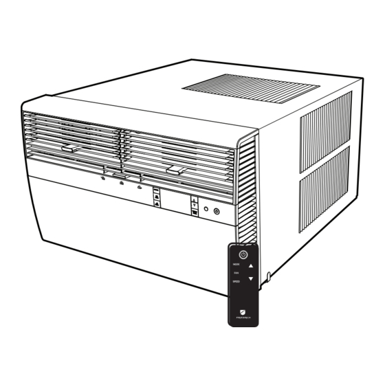
- Page 1 Kuhl Series ® Room Air Conditioners Standard Chassis Models Using R-32 Refrigerant Kühl 230-Volt: KCL36 115-Volt: KHS10 Kühl + Heat Pump THE EXPERTS IN ROOM AIR CONDITIONING 92000021_00...
-
Page 2: Table Of Contents
Register your Air Conditioner Model information can be found on the name plate. Please complete and mail the owner registration card fur- nished with this product, or register online at www.friedrich. com. For your future convenience, record the model information in Section R, information for the owner. -
Page 3: Important Safety And General Information
A. IMPORTANT SAFETY AND GENERAL INFORMATION A.1 Introduction This booklet contains the installation and operating instructions for your Air Conditioning unit. There are some precautions that should be taken to ensure proper operation. Improper installation can result in unsatisfactory operation or dangerous conditions. Read this booklet and any instructions packaged with separate equipment required to make up the system prior to installation. -
Page 4: Safety Warnings
CAUTION: Do Not Operate Equipment During Active Stages Of Construction To ensure proper operation, Friedrich requires that all equipment is not operated during active construction phases. This includes active stages of completing framing, drywalling, spackling, sanding, painting, flooring, and moulding in the equipment’s designated conditioning space. The use of this equipment during construction could result in premature failure of the components and/or system and is in violation of our standard warranty guidelines. - Page 5 A. IMPORTANT SAFETY AND GENERAL INFORMATION A.4.1 Unpacking Instructions A.4.2 Unpacking Instructions (Small and Medium Chassis) (Large Chassis) STEP 1. Cut all 4 packing straps. STEP 1. Cut all 4 packing straps. STEP 2. Remove wooden shipping bar dividers. STEP 2. Slowly remove outer box, careful not to loosen decorative front. STEP 3.
-
Page 6: Importance Of A Quality Installation
Opening of any ventilated Any tubing or refrigerant circuit work Opening of any sealed components Enclosures beyond the hinged door for filter cleaning Scan this QR code to be linked to the Friedrich professional support page where you can locate the Service Manual. -
Page 7: Product Inspection / Packing List
A. IMPORTANT SAFETY AND GENERAL INFORMATION A.6 Packing List 14 14 Thru-the-Wall Window Mount Installation Hardware Installation Hardware ITEM DESCRIPTION QTY. ITEM DESCRIPTION QTY. MOUNTING PARTS WINGBOARD MOUNTING PARTS WINGBOARD (MASONITE) SCREW, SHEET METAL #12A x 2″ “J” TYPE SPEED NUT CHASSIS SEAL GASKET (LIGHT FOAM) WINGBOARD CLIP (SPRING STEEL) SCREW, #8 x ½″... -
Page 8: Specifications
Please note that Wireless Programming and Control: junction and electrical boxes are not acceptable for outdoor use. Friedrich Connect allows you to conveniently control, program, and monitor your air conditioning unit remotely from a smartphone or computer. Pre-Programmed Timer Options: Your unit’s digital control comes equipped with a 24-hour timer. -
Page 9: Installation Of The Unit
C. INSTALLATION OF THE UNIT C.1 Pre-Installation Checkpoints C.3. Choosing a Location Installation Clearances Before attempting any installation, carefully consider the Improper installation of the Air Conditioner can cause poor perfor- following points: mance and premature wear of the unit. Ensure that the KUHL unit is installed with proper clearances as •... -
Page 10: Window Installation
C. INSTALLATION OF THE UNIT C.4 Window Installation NOTE: Hardware used during the installation is illustrated in section A. 6 STEP 1. Remove the chassis EntryGard retainer by removing the far right ™ screw (see Figure C.4.1). Save this screw to reattach the chassis retainer after installation (Step 12). - Page 11 C. INSTALLATION OF THE UNIT C.4 Window Installation (Continued) Alternate support method A: If you have a deep window sill which prevents you STEP 4. Check the window sill and frame to be sure they are in good from mounting the brackets as shown in Figure C.4.8, try the following: Using the condition and functioning.
- Page 12 C. INSTALLATION OF THE UNIT C.4 Window Installation (Continued) #8 x ″ LONG SCREW (ITEM 7) 2 REQUIRED TOP ANGLE (ITEM 5) CABINET Detail 2 SIDE ANGLE (ITEM 6) 2 REQUIRED LOOP SILL PLATE Detail 1 Figure C.4.4 TOP ANGLE CENTER (ITEM 5) CABINET...
- Page 13 C. INSTALLATION OF THE UNIT C.4 Window Installation (Continued) ″ SLOPE DOWN #10-24 x 1″ HEX HEAD SCREW (ITEM 2) SUPPORT BRACKET (ITEM 1) #12 x 2″ SCREW SUPPORT (ITEM 4) BRACKET SPACER SHOULD BE USED BETWEEN (ITEM 1) WALL AND BRACKET WHEN INSTALLED ON ALUMINUM OR VINYL SIDING.
- Page 14 C. INSTALLATION OF THE UNIT C.4 Window Installation (Continued) FOR LEDGES ″ SLOPE DOWN CONDENSER AIR INLETS #10-24 SCREW #10-24 FLAT WELD NUT #12 x 2″ SHEET METAL SCREW (ITEM 4) STONE LEDGE SPACER Figure C.4.8 ALTERNATE METHOD A ″ SLOPE DOWN #10-24 SCREW STRAIGHTEN TAB TO LAY FLAT ALONG THE BOTTOM RAIL OF...
- Page 15 C. INSTALLATION OF THE UNIT C.4 Window Installation (Continued) ALTERNATE METHOD B ″ SLOPE DOWN #10-24 SCREW DIMENSION “A” CUT TO FIT DIMENSION “A” CUT HERE AND BEND DOWN TO FORM A VERTICAL LEG. #10-24 FLAT WELD NUT STONE LEDGE OUTSIDE WALL DISCARD SHAD- ED AREA...
- Page 16 C. INSTALLATION OF THE UNIT C.4 Window Installation (Continued) WARNING CAUTION Cut/Sever Falling Object Hazard Although great care has been taken to minimize sharp edges in the construction of your unit, Not following Installation Instructions use gloves or other hand for mounting your air conditioner can protection when handling unit result in property damage, injury, or...
- Page 17 C. INSTALLATION OF THE UNIT C.4 Window Installation (Continued) INSERT FOAM WINDOW SEAL GASKET (ITEM 12) TOP OF CABINET PLACE WINGBOARD PANEL IN WINDOW JAM TO COMPRESS THE SPRINGS INSIDE THE RUNNERS, AND SWING THE WINGBOARD PANELS INTO PLACE AS INDICATED BY THE DASHED LINES.
- Page 18 C. INSTALLATION OF THE UNIT C.4 Window Installation (Continued) OPTIONAL: The factory assembles the supply cord so that it exits the left side of the unit at the bottom. At the consumer’s discretion, pull the supply cord taut through the loops (refer to Cord Routing Change, Section C.6) and route the cord down.
-
Page 19: Thru-The Wall Installation
C. INSTALLATION OF THE UNIT C.5 Thru-the Wall Installation NOTE: Hardware used during the installation is illustrated in section A. 6 STEP 1. Remove the chassis EntryGard ™ retainer by removing the far right screw (see Figure C.5.1). Save this screw to reattach the chassis retainer after installation (Step 12). - Page 20 C. INSTALLATION OF THE UNIT C.5 Thru-the Wall Installation (Cont.) TOP VIEW OF UNIT REMOVE AND DISCARD SCREWS BACK CONDENSOR COIL RIGHT SIDE LEFT SIDE COMPRESSOR FAN MOTOR EVAPORATOR COIL REMOVE AND SAVE SCREW FOR RE-INSTALLATION Figure C.5.3...
- Page 21 C. INSTALLATION OF THE UNIT C.5 Thru-the Wall Installation (Cont.) WARNING Falling Object Hazard Not following Installation Instructions for mounting your air conditioner can result in property damage, injury, or death. The following instructions apply to wood, masonry, brick, concrete or cinder block wall construction.
- Page 22 C. INSTALLATION OF THE UNIT C.5 Thru-the Wall Installation (Cont.) BEFORE AFTER CABINET CABINET SCREW (4 REQUIRED) NOTE: HOLES IN SILL SILL PLATE (4 REQUIRED) PLATE MOVED TO BACK SIDE DETAIL 1 TURN SILL PLATE END TO END DETAIL 3 (4 REQUIRED) DETAIL 2 SCREW...
- Page 23 C. INSTALLATION OF THE UNIT C.5 Thru-the Wall Installation (Cont.) CAULK ALL SIDES INSIDE AND OUTSIDE CAULK ALL SIDES INSIDE AND OUTSIDE CABINET CABINET SHIM TO FILL IN VOID AT THE TOP AND SIDE WITH WOOD SHIM TO FILL IN VOID AT THE AS REQUIRED.
- Page 24 C. INSTALLATION OF THE UNIT C.5 Thru-the Wall Installation (Cont.) STEP 8. Slide the cabinet into the hole far enough to allow the guide-channel NOTE: DO NOT LEVEL the cabinet from front to back. Make sure there of the sill plate to contact the inside wall surface (Figure C.5.9). is approximately ″...
- Page 25 C. INSTALLATION OF THE UNIT C.5 Thru-the Wall Installation (Cont.) NOTE: WHEN INSTALLING THE CHASSIS POWER CORD CLIP SEAL GASKET, BEGIN AT EITHER BOTTOM CORNER AND GO UP THE SIDE & ACROSS THE TOP & DOWN THE OPPOSITE SIDE. CHASSIS SEAL GASKET (ITEM 13) FRR024 Figure C.5.10 OPTIONAL: The factory assembles the supply cord so that it exits the left side...
- Page 26 C. INSTALLATION OF THE UNIT C.6 Cord Routing Change Unplug unit. STEP 2. Carefully pull out electrical control panel 1″, but not all the way. WARNING Electrical Shock Hazard Make sure your electrical receptacle has the same configuration as your air conditioner’s plug.
- Page 27 C. INSTALLATION OF THE UNIT C.6 Cord Routing Change STEP 5. Carefully push electrical control panel back into chassis. STEP 7. If running power cord to the right of the unit, install the cord into the cord retainer clips along the bottom front of the unit. ELECTRICAL CONTROL PANEL CORD RETAINER...
-
Page 28: Install Filter
C. INSTALLATION OF THE UNIT C.7 Install Filter TOP TAB FRONT FRAME WITH STANDARD MESH FILTER Figure C.7.4 STEP 1. Swing the door open and remove the filter by grasping the filter grip and pushing the filter holder upward and outward. (See Figure C.7.2) STEP 2. -
Page 29: Electrical
E. ELECTRICAL Electrical Safety Information Testing the Power Cord All Friedrich room air conditioners are shipped from the factory with a Leakage Current Detection Interrupter (LCDI) equipped power WARNING cord. The LCDI device on the end of the cord meets the UL and NEC requirements for cord connected air conditioners. -
Page 30: Startup And Operation
J. STARTUP AND OPERATION J.1 Final Inspection J.2 Air Flow Selection and Adjustment Airflow direction adjustment • Inspect and ensure that all components and accessories have been installed properly and that they have not been damaged The airflow path may be adjusted to distribute air independently from the left or during the installation progress. -
Page 31: Control Panel Operation
J. STARTUP AND OPERATION J.3 Control Panel Operation All of the control panel function buttons and mode icons can be viewed in Figure 8. Power On – Press the button to turn on the air conditioner. The power button illuminates to indicate that the power is on. The backlight on the power switch will automatically turn off after 20 seconds of inactivity. - Page 32 J. STARTUP AND OPERATION J.3 Control Panel Operation Accessing Sub-Menus The MENU button accesses the sub-menu. See Figure J.3.3. The arrow buttons navigate the 6 menu options See Figure J.3.4: – LIM – LOCK – TM – CnCT – F-C –...
- Page 33 J. STARTUP AND OPERATION J.3 Control Panel Operation Navigating Inside the Sub-Menus The MENU button moves you forward through the sub-menu. See Figure J.3.6. The RETURN button moves you backward once inside the LIM and TM menus. See Figure J.3.7. Figure J.3.6 MENU...
- Page 34 J. STARTUP AND OPERATION J.3 Control Panel Operation The LIM Menu Then you can set the higher setpoint limit using the arrow buttons. This is the limit menu. See Figure J.3.8. See Figure J.3.10. Upon entering the menu, the first option will be to set the lower setpoint limit using the arrow buttons.
- Page 35 J. STARTUP AND OPERATION J.3 Control Panel Operation Using the button, you switch to the minutes and complete setting the The TM Menu time. See Figure J.3.14. This is the TM menu used to set a timer. See Figure J.3.12. You select your mode.
- Page 36 J. STARTUP AND OPERATION J.3 Control Panel Operation The TM Menu continued Auto mode selected. See Figure J.3.16. Note: The auto mode timer sets both the cool and heat setpoint. Set the cool setpoint for your first timer period using the arrow buttons. Set the time to start the first timer period.
- Page 37 J. STARTUP AND OPERATION J.3 Control Panel Operation The TM Menu continued Set the cool setpoint for the second scheduled timer. See Figure J.3.20. Set the heat setpoint for the second timer. Set the time to start the second timer period. See Figure J.3.21. Press the button to complete the time timer setup.
- Page 38 J. STARTUP AND OPERATION J.3 Control Panel Operation The F-C Menu This menu is used to toggle between Fahrenheit and Celsius. This is the Fahrenheit/ Celsius Menu. See Figure J.3.23 Using the arrow buttons on the right side switches it from Fahrenheit to Celsius.
- Page 39 J. STARTUP AND OPERATION J.3 Control Panel Operation The Lock Menu This menu is used to lock the changing setting with a password. This is LOCK on. See Figure J.3.28. This is the Lock Menu. See Figure J.3.26. Set the first digit of the password using the arrow buttons. Use the button to proceed to the next digit.
- Page 40 J. STARTUP AND OPERATION J.3 Control Panel Operation The Lock Menu continued Set the second digit of the password using the same method. Set the fourth digit of the password using the same method. See Figure J.3.30 See Figures J.3.32 Set the third digit of the password using the same method.
- Page 41 J. STARTUP AND OPERATION J.3 Control Panel Operation The Lock Menu continued The ON on the right side of the display shows the lock function is Entering the correct password will give the user access to all of the sub- active.
- Page 42 J. STARTUP AND OPERATION J.3 Control Panel Operation The CnCT Menu This menu is used to turn on Wi-Fi connection. This is the CnCT menu. Pressing the button will activate Wi-Fi. See Figure J.3.38 The Wi-Fi symbol in the top right corner of the display shows Wi-Fi connection is on.
- Page 43 J. STARTUP AND OPERATION J.3 Control Panel Operation The diAG Menu This menu is used to access the diagnostic codes. See Figure J.3.40. Selecting this sub-menu shows the E that represents “Error.” See Figure J.3.41 Toggle through the error codes using the arrow keys. See Figure J.3.42 Figure J.3.40 MENU...
-
Page 44: Remote Control Operation
Noises operation. When the FAN SPEED button is pressed, the fan speed icon (triangle) All air conditioners make some noise. Friedrich units are designed to changes to indicate the new speed level. Fan speed automatically varies depending operate as quietly as possible. An air conditioner mounted in a wall is on the set temperature on the control panel and the actual room temperature. -
Page 45: Troubleshooting
M. TROUBLESHOOTING M.1. Troubleshooting Tips COMPLAINT CAUSE SOLUTION • • The unit is turned to the off position, or the Turn the unit to the on position and raise or lower temperature thermostat is satisfied. setting (as appropriate) to call for operation. •... -
Page 46: Diagnostic Codes
M. TROUBLESHOOTING M.1. Troubleshooting Tips (Cont) COMPLAINT CAUSE SOLUTION • Do not try to operate your air conditioner in the cooling mode • The outside temperature is below 60 °F when the outside temperature is below 60 °F (16 °C). The unit will (16 °C). -
Page 47: Appendixes
Window Installation Kits (Standard in Kühl Models without Heat) KWIKS – For all KES and KHS models. KWIKM – For all KEM and KHM models. KWIKL – For all KEL and KHL models. See www.friedrich.com for additional accessories for your unit. -
Page 48: Information For The Owner
Area Required Area Required Authorized Friedrich Warranty Service Company in the area for 100 - 150 5000 550 - 700 14000 future reference if necessary. Inspect the unit for any damage to the coils and tubing that could cause a leak. -
Page 49: Warranty
R. INFORMATION FOR THE OWNER R.3 Warranty...
Need help?
Do you have a question about the Kuhl KCL36 and is the answer not in the manual?
Questions and answers
what is the dimensions of the 10000 btu kuhl ac and heat pump will it fit my freidich 10000 btu ac box or do i need to put the new box in