
Subscribe to Our Youtube Channel
Related Manuals for Friedrich KP05A10 KP06A10


Summary of Contents for Friedrich KP05A10 KP06A10
- Page 1 Room Air Conditioner Service and Parts Manual KP Line KP05A10 KP06A10 KP05 / KP06 (03/03)
-
Page 2: Table Of Contents
1. PREFACE ...3 1.1 FEATURES...3 1.2 SPECIFICATIONS ...3 1.3 LOCATIONS OF CONTROLS ...4 1.4 SAFETY PRECAUTIONS ...4 1.5 INSULATION RESISTANCE TEST ...4 2. DISASSEMBLY INSTRUCTIONS 2.1 MECHANICAL PARTS ...5 2.1.1 FRONT GRILLE ...5 2.1.2 CABINET...5 2.1.3 CONTROL BOARD ...5 2.2 AIR HANDLING PARTS ...6 2.2.1 AIR GUIDE UPPER ...6 2.2.2 ORIFICE, TURBO FAN AND FAN ...6 2.2.3 MOTOR ...7... -
Page 3: Preface
This service manual provides various service information, including the mechanical and electrical parts, etc. This room air conditioner was manufactured and assembled under a strict quality control system. The refrigerant is charged at the factory. Be sure to read the safety precautions prior to servicing the unit. -
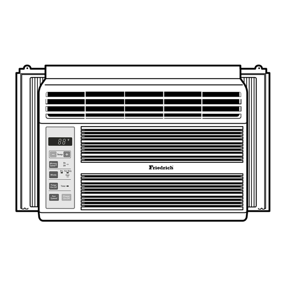
Page 4: Locations Of Controls
• Everytime you push this button, it will rotate between the COOL, FAN and DRY modes. ON/OFF TIMER ON–When the air conditioner is off, it can be set to automatically come on in 1 to 12 hours from its previous setting. Each touch will increase the timer by 1 hour. -
Page 5: Disassembly Instructions
2. DISASSEMBLY INSTRUCTIONS 2.1 MECHANICAL PARTS 2.1.1 FRONT GRILLE 1. Pull the inlet grille forward. 2. Remove the screw securing the Front Grille. (Fig. 3) 3. Push the grille up from the bottom and pull the top of the grille away from the case to lift the top tabs out of their slots. -
Page 6: Air Handling Parts
2.2 AIR HANDLING PARTS 2.2.1 AIR GUIDE UPPER 1. Disconnect the unit from the power source. 2. Remove the front grille. (Refer to Section 2.1.1) 3. Remove the cabinet. (Refer to Section 2.1.2) 4. Remove the control board. (Refer to Section 2.1.3) 5. -
Page 7: Motor
2.2.3 MOTOR 1. Disconnect the unit from the power source. 2. Remove the front grille. (Refer to Section 2.1.1) 3. Remove the cabinet. (Refer to Section 2.1.2) 4. Remove the control board. (Refer to Section 2.1.3) 5. Remove the air guide upper. (Refer to Section 2.2.1) 6. -
Page 8: Compressor
2.3.2 COMPRESSOR 1. Remove the front grille and cabinet. (Refer to Section 2.1) 2. Discharge the refrigerant by using a refrigerant recovery system. 3. Remove the overload protector. (Refer to Section 2.3.1) 4. After discharging the unit completely, unbrace the suction and discharge pipes at the compressor connections. -
Page 9: Power Cord
2.3.6 POWER CORD 1. Disconnect the unit from source of power. 2. Remove the front grille. (Refer to Section 2.1.1) 3. Remove the cabinet. (Refer to Section 2.1.2) 4. Remove a screw that secures control board to base pan. (Refer to Section 2.1.3) 5. -
Page 10: Evaporator
2.4.2 EVAPORATOR 1. Remove the cabinet. 2. Discharge the refrigerant by using a refrigerant recovery system. 3. Remove the air guide upper. (Refer to Section 2.2.1) 4. After discharging the refrigerant completely, unbraze the interconnecting tube at the condenser connections. 5. - Page 11 Equipment needed: Vacuum pump, charging cylinder, manifold gauge, brazing equipment, pinch-off tool capable of making a vapor proof seal, leak detector, tubing cutter, hand tools to remove components and service valve. CONDENSER (HIGH PRESSURE SIDE) COMPRESSOR EXTERNAL VACUUM PUMP Figure 21A-Pulling Vacuum COMPOUND GAUGE MANIFOLD GAUGE...
-
Page 12: Installation
3. INSTALLATION This air conditioner is designed with a button-down chassis so it can be easily installed in a window. 3.1 SELECT THE BEST LOCATION 1. To prevent vibration and noise, make sure the unit is installed securely and firmly. -
Page 13: Before Installation
Installation HARDWARE TYPE A: 11EA (SHORT SCREW) TYPE D: 1EA (SEAL STRIP) (Adhesive backed) (Not adhesive backed) 3.2.2 BEFORE INSTALLATION 1. Insert the guide panels into the guides of the air condi- tioner. Fasten the curtains to the unit with screws (TYPE A) as shown Figure. - Page 14 3. INSTALL THE AIR CONDITIONER IN THE WINDOW a. Carefully lift the air conditioner and slide it into the open window. Make sure the bottom guide of the air conditioner drops into the notches of the L bracket. See Figure. 28.
-
Page 15: Electrical Data
REMOVAL FROM WINDOW Turn the air conditioner off, disconnect the power cord, remove the L bracket and the screws installed through the top and bot- tom of the guide panels, and save for reinstallation later. Close the guide panels. Keeping a firm grip on the air conditioner, raise the sash, and carefully tilt the air conditioner backward, draining any condensate water. -
Page 16: Piping System
EVAPORATOR COILS COMPLETE LIQUID BOIL OFF POINT COOLED ROOM AIR HEAT LOAD LIQUID PRESSURE DROP ROOM AIR CONDITIONER CYCLE OF REFRIGERATION VAPOR INLET SUCTION LINE COOL LOW PRESSURE VAPOR OUTSIDE COOLING AIR FOR REFRIGERANT PASS THROUGH MOTOR... -
Page 17: Troubleshooting Guide
4.3 TROUBLESHOOTING GUIDE In general, possible trouble is classified in two kinds. The one is called Starting Failure which is caused by an electrical defect. The other is Ineffective Air Con- ditioning caused by a defect in the refrigeration circuit and improper application. Unit is running but cooling is ineffective. - Page 18 Check of power source. Check of control switch setting. Compressor fails only to start. Drop of power voltage. Defect of compressor capacitor. Capacitor check. Replacement. Irregular motor resistance ( ) Irregular motor insulation ( ) Replacement of compressor (Motor damaged). Fails to Start Improper thermostat setting...
- Page 19 ROOM AIR CONDITIONER VOLTAGE LIMITS NAME PLATE RATING 115V ± 10% COMPLAINT Fan motor will not run. No power Power supply cord Wire disconnected or connection loose Capacitor (Discharge capacitor before testing.) Will not rotate Fan motor runs. Revolves on overload...
- Page 20 COMPLAINT Fan motor noise. Blower Loose set screw Worn bearings Compressor will not run, Voltage fan motor runs. Wiring Thermistor Capacitor (discharge capacitor before servicing.) Compressor Overload Compressor cycles on Voltage overload. Overload CAUSE If cracked, out of balance, or partially missing, replace it.
- Page 21 COMPLAINT Compressor cycles on Fan motor overload. Condenser air flow restriction Condenser fins (damaged) Capacitor Wiring Refrigeration system Insufficient cooling Air filter Unit undersized Excessive noise Blower or fan Copper tubing CAUSE If not running, determine the cause. Replace if required.
-
Page 22: Circuit Diagram
5. CIRCUIT DIAGRAM LOCATION DESCRIPTION POWER CORD ASSY FAN MOTOR COMPRESSOR THERMISTOR CAPACITOR OVERLOAD PROTECTOR POWER INPUT WH(BL) BK(BR) (Ribbed) (Plain) GN/YL(GN) THERMISTOR MOTOR OR(BR) OR(BR) GN/YL (GN) CAPACITOR RY-COMP COMP. FUSE 3854A20022K WIRING DIAGRAM KP05A10 4681A10002R 5416A20014D 6750A30001U —22— CN-TH1 SYNC MOTOR... -
Page 23: Exploded View
6. EXPLODED VIEW 132111-1 132111-2 159900-2 152302 135303 135313 W0CZZ 264110 137215 268714 238310 268712 249950 130910 267110 349480 135312 145200 359012 W48602 159900-1 354210 263230 550140 —23— 559011 148000 554030 149980 352390-1 130410 552102 352111 352115 567502 554160 35211A W48602 346811 352390... -
Page 24: Service Parts List
COMPRESSOR 559011 FAN,PROPELLER 567502 O.L.P W0CZZ CAPACITOR,DRAWING W48602 CLAMP,SPRING 132111-1 FRAME ASSEMBLY 132111-2 FRAME ASSEMBLY 352111 TUBE ASSEMBLY,FORMED COND PART NO. FRIEDRICH PART NO. KP05A10 KP06A10 KP05A10 3041A10011F 3091A10020A 3531A10130D 3530A10157A 3550A30048A 3550U-L006A 67301202 4520AR3191A 5990AR3190A 5990AR3190B 4800A30003A 4998A10008A 5231AR2148G... - Page 25 MEMO —25—...
- Page 26 MEMO —26—...
- Page 27 Use Factory Certified Parts... FRIEDRICH AIR CONDITIONING CO. Visit our web site at www.friedrich.com Post Office Box 1540 • 4200 N. Pan Am Expressway • San Antonio, Texas 78295-1540 • (210) 357-4400 • FAX (210) 357-4480 P/NO.:3828A20207D KP05 / KP06 (03/03)
Need help?
Do you have a question about the KP05A10 KP06A10 and is the answer not in the manual?
Questions and answers