
Subscribe to Our Youtube Channel
Related Manuals for Friedrich Kuhl KCQ06A10A


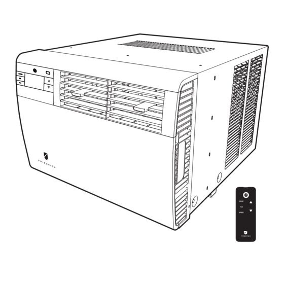
Summary of Contents for Friedrich Kuhl KCQ06A10A
- Page 1 Room Air Conditioners Q Chassis Models Kühl 115-Volt: KCQ06A10A, KCQ08A10A, KCQ10A10A, KCQ10A10B Kühl + 115-Volt: KEQ08A11A Electric Heat 93001404_03...
-
Page 2: Table Of Contents
Table of Contents INTRODUCTION Important Safety Information Personal Injury Or Death Hazards Kühl Control Options Component Identification User Interface Model and Serial Number Location Model Number Reference Guide Serial Number Reference Guide SPECIFICATIONS Refrigeration Systems Performance Data Installation Electrical Data Circuit Rating/ Breaker/ power cord/ wall Receptacle OPERATION Airflow Direction... -
Page 3: Introduction
INTRODUCTION Important Safety Information The information in this manual is intended for use by a qualified technician who is familiar with the safety proce- dures required for installation and repair, and who is equipped with the proper tools and test instruments required to service this product. -
Page 4: Personal Injury Or Death Hazards
INTRODUCTION Personal Injury Or Death Hazards WARNING AVERTISSEMENT ADVERTENCIA Do not remove, disable or Ne pas supprime, désactiver ou No eliminar, desactivar o pasar SAFETY bypass this unit’s safety contourner cette l´unité des por alto los dispositivos de devices. Doing so may cause dispositifs de sécurité, faire vous seguridad de la unidad. - Page 5 INTRODUCTION PERSONAL INJURY OR DEATH HAZARDS • REFRIGERATION SYSTEM REPAIR HAZARDS: • Use approved standard refrigerant recovering procedures and equipment to relieve high pressure before opening system for repair. Reference EPA regulations (40 CFR Part 82, Subpart F ) Section 608. •...
-
Page 6: Kühl Control Options
The 24-hour timer allows you to set 2 temperature changes at pre-set times on the unit control panel. Customizable Programming Options: Customizable timers, with up to four temperature adjustments per day, can be set using Friedrich Connect for one or multiple units. www.friedrich.com for complete details on Friedrich Connect. -
Page 7: Component Identification
This service manual was written to assist the professional service technician to quickly and accurately diagnose and repair malfunctions. Installation procedures are not given in this manual. They are given in the Installation/Operation manual which can be aquired on the Friedrich website. Component Identification Condensor Coil... -
Page 8: Model Number Reference Guide
INTRODUCTION Model Number Reference Guide K C M 21 A 1 0 A - A ENGINEERING REVSION LETTER INDICATES AN ENGINEERING MODIFI- CATION TO AN EXISTING MODEL TYPE MODEL K - KUHL W - WALLMASTER MARKETING SUFFIX LETTER INDICATES MODIFICATION TO AN EXISTING MODEL FUNCTION C - COOL ONLY... -
Page 9: Serial Number Reference Guide
19 = 2019 20 = 2020 21 = 2021 22 = 2022 MONTH OF MANUFACTURE 01 = JANUARY FACTORY DESIGNATION 02 = FEBRUARY M = FRIEDRICH MTY 03 = MARCH 04 = APRIL 05 = MAY 06 = JUNE 07 = JULY... -
Page 10: Specifications
SPECIFICATIONS Refrigeration Systems Performance Data R-410A Electrical Ratings REF. Breaker Conden- Discharge Suction LOCKED sor Temp Temp Temp AMPS AMPS ROTOR CHARGE HERTZ Model Deg. F Deg F Deg F COOL HEAT AMPS IN OZ Voltage AMPS Kühl (Cool Only) ®... -
Page 11: Installation
SPECIFICATIONS Installation Depth Shell Window Width In-wall Installation Carton Dimensions with Front Depth INCHES Finished Hole Inches Inches Minimum Minimum Inches to Louvers Extension Extension Inches Max. Depth Width Into Room* Outside Height Sleeve Inches Inches Inches * Inches Minimum** Maximum Height Width... -
Page 12: Electrical Data
SPECIFICATIONS Electrical Data WARNING NOTICE ELECTRIC SHOCK HAZARD Turn off electric power before service or installation. FIRE HAZARD All electrical connections and wiring MUST be electically unsafe conditions which could cause moderate the National Electrical Code and all local codes or serious property damage. - Page 13 Under no circumstances should you remove the ground prong from the plug. Test the power cord. All Friedrich room air conditioners are shipped from the factory with a Leakage Current Detection Interrupter (LCDI) equipped power cord. The LCDI device on the end of the cord meets the UL and NEC requirements for cord connected air conditioners.
-
Page 14: Operation
OPERATION Airflow Direction The airflow path may be adjusted to distribute air independently from the left or right side of the discharge opening. Each of the banks of louvers can be directed left, right, up, or down in order to achieve the most optimum airflow positioning. To adjust airflow direction, grab the lever in the center of the louver bank and move it in the direction that you would like the air to be directed. -
Page 15: User Interface
OPERATION User Interface All of the control panel function buttons and mode icons can be viewed in Figure 302. Power On – Press the button to turn on the air conditioner. The power button illuminates to indicate that the power is on. The backlight on the power switch will automatically turn off after 20 seconds of inactivity. - Page 16 OPERATION User Interface Accessing Sub-Menus The MENU button accesses the sub-menu. See Figure 10. The arrow buttons navigate the 6 menu options (See Figure 306): – LIM – LOCK – TM – CnCT – F-C – diAG The return button exits the menu. See Figure 305. Figure 304 MENU RETURN Figure 305...
- Page 17 OPERATION User Interface Navigating Inside the Sub-Menus The MENU button moves you forward through the sub-menu. See Figure 307. The return button moves you backward once inside the LIM and TM menus. See Figure 308. Figure 307 MENU RETURN Figure 308 MENU RETURN...
- Page 18 OPERATION User Interface The LIM Menu (Limit) This is the limit menu. See Figure 309. Upon entering the menu, the first option will be to set the lower setpoint limit using the arrow buttons. See Figure 310. Then you can set the higher setpoint limit using the arrow buttons. See Figure 311. Pressing the menu button completes the limit setting.
- Page 19 OPERATION User Interface The TM Menu (Timer) This is the TM menu used to set a timer. See Figure 313. In the menu, you set the current time using the arrow buttons. See Figure 314. (Note: These two “set clock” steps will be skipped if the unit is already connected to Wi-Fi.) First, set the hour.
- Page 20 OPERATION User Interface The TM Menu (Timer)continued Auto mode selected. See Figure 317. Set the cool setpoint for your first timer period using the arrow buttons. The cooling mode timer only sets the cool setpoint. See Figure 318. Next, set the heat setpoint for your first timer period. The heating mode timer only sets the heat setpoint. See Figure 319. Note: The auto mode timer sets both the cool and heat setpoint.
- Page 21 OPERATION User Interface The TM Menu (Timer) continued Set the cool setpoint for the second scheduled timer. See Figure 321. Set the heat setpoint for the second timer. Set the time to start the second timer period. See Figure 322. Press the MENU button to complete the time timer setup.
- Page 22 OPERATION User Interface The F-C Menu (Fahrenheit/ Celsius) This menu is used to toggle between Fahrenheit and Celsius. See Figure 324. Using the arrow buttons on the right side switches it from Fahrenheit to Celsius. See Figures 325 and 326. Figure 324 MENU RETURN Figure 325...
- Page 23 OPERATION User Interface The Lock Menu NOTICE This menu is used to lock the settings with a four(4) digit passcode. Be sure to write down your passcode if you activate This is the Lock Menu. See Figure 327. this feature. Please contact technical support if you The menu lock is defaulted to off.
- Page 24 OPERATION User Interface The Lock Menu continued The ON on the right side of the display shows the lock function is active. To go back into the menu, select the menu button again. See Figure 331. Enter the password in the same manner it was created. See Figure 332. Entering the correct password will give the user access to all of the sub-menus.
- Page 25 OPERATION User Interface The CnCT (WiFi Connection) Menu This menu is used to turn on Wi-Fi connection. This is the CnCT menu. Pressing the leftmost button will activate Wi-Fi. See Figure 335. To setup WiFi, refer to Wi-Fi setup instructions. The Wi-Fi symbol in the top right corner of the display shows Wi-Fi connection is on.
- Page 26 OPERATION User Interface The diAG Menu This menu is used to access the diagnostic codes. See Figure 337. Selecting this sub-menu shows the E that represents “Error.” See Figure 338. Toggle through the error codes using the arrow keys. See Figure 339. Figure 337 MENU RETURN Figure 338...
-
Page 27: Control Panel
OPERATION Control Panel SYSTEM - The MODE button allows you to sequentially select up to four modes of operation: AUTO Available on select models COOL HEAT Available on select models FAN ONLY AUTO FAN (No Cooling Demand) When in AUTO mode, the fan only operates when the system has a demand to cool or heat the room. In the ON fan mode, the fan operates all the time. -
Page 28: Remote Control
OPERATION Remote Control Remote Control - Refer to Figure 340A during operation description. Getting Started - Install two (2) AAA batteries in the battery compartment located on the back of the unit. Operation - The remote control should be within 25 feet of the air conditioner for operation (refer to Figure 340B for effectiveness). Press the power button to turn the remote on. -
Page 29: Unit
Noises Friedrich units are designed to operate as quietly as possible. An air conditioner mounted in a wall is quieter than one mounted in a window. It is important to ensure that the chassis seal gasket is properly installed (refer to SPECIFICATIONS FIGURE 205). - Page 30 OPERATION Heat Control Operation - Electric Heat Only (KEQ08A11A) When in the Heat mode, with and without Fan Mode Auto (Fan cycling): If the indoor ambient temperature is below the Heat Demand Threshold (Heat Set Point minus 1.5 ˚F), turn on electric heat.
- Page 31 OPERATION Heating Fan Delay This is only for fan Mode Auto (Fan cycles with cool/heat operation) and not for continuous fan mode. When unit cycles Heating ON – starts the fan 5 seconds EARLY. When unit cycles Heating OFF – DELAYS the fan off for 15 seconds.
-
Page 32: General Knowledge Sequence Of Refrigeration
OPERATION General Knowledge Sequence Of Refrigeration A good understanding of the basic operation of the refrigeration system is essential for the service technician. Without this understanding, accurate troubleshooting of refrigeration system problems will be more difficult and time consuming, if not (in some cases) entirely impossible. -
Page 33: Routine Maintenance
ROUTINE MAINTENANCE REMOVE AND INSTALL THE FRONT COVER Remove the decorative front cover. WARNING 1.Remove screws if installed. EntryGard™ 2. Open the decorative front cover door. ELECTRIC SHOCK HAZARD 3. Locate and disconnect electronic control power Disconnect power to the unit before cable harness. - Page 34 ROUTINE MAINTENANCE Coils & Chassis NOTE: Do not use a caustic (alakaline) or acidic cleaning agent on coils or base pan. Use a biodegradable cleaning agent and degreaser. The use of harsh cleaning materials may lead to deterioration of the aluminum fins or the coil end plates.
- Page 35 ROUTINE MAINTENANCE FILTER REMOVAL / INSTALLATION INSTRUCTIONS Swing the door open, See Figure 402,and remove the filter by grasping the filter grips and pulling the bottom towards you. . See Figure 403. Clean the front frame by removing the carbon filter (if installed) and washing the dirt from the filter. Use a mild soap solution if necessary. Allow filter to dry.
-
Page 36: Remove And Install The Chassis
REMOVE AND INSTALL THE CHASSIS REMOVE AND INSTALL THE CHASSIS Remove the chassis WARNING 1. Remove the EntryGard™ Screws. (Refer to Figure 501) ELECTRIC SHOCK HAZARD Disconnect power to the unit before 2. Hold the cabinet stationary then carefully slide the servicing. -
Page 37: Troubleshooting
IS THE FRESH / EXHAUST AIR VENT OPEN? _____ ____ 150 - 250 6000 IS A FRIEDRICH SLEEVE INSTALLED? _____ ____ 250 - 300 7000 IS A FRIEDRICH OUTDOOR GRILLE INSTALLED? _____ ____ IS MAINTENANCE BEING PERFORMED? _____ ____ 300 - 350 8000 350 - 400 9000... -
Page 38: Diagnostic Codes
TROUBLESHOOTING Diagnostic Codes FAULT PROBLEM CONTROL BOARD'S ACTION CODE Front Panel Button Stuck For More Continue to monitor for "OPEN" (Unstuck) switch. Do not process Than 20 Seconds switch input. ENSURE FRONT COVER DOES NOT DEPRESS BUTTONS Indoor Temperature Sensor is Open Set temp to 75°F in COOLING or 68°F in HEATING. - Page 39 TROUBLESHOOTING Tips Problem Possible Cause Possible Solution Push the power button on and raise or lower The power button is off or the set point temperature setting (as appropriate) to call for temperature is satisfied. operation. Plug into a properly grounded 3 prong receptacle. The LCDI power cord is unplugged.
-
Page 40: Tips
TROUBLESHOOTING Tips Continued COMPLAINT CAUSE SOLUTION Do not try to operate your air conditioner in the Operating in Cooling mode while the cooling mode when the outside temperature is outside temperature is below 60 °F below 60 °F (16 °C). The unit will not cool prop- (16 °C). - Page 41 TROUBLESHOOTING Tips Continued COMPLAINT CAUSE SOLUTION Test button & replace user interface if inopera- Inoperative system button tive Broken, loose or incorrect wiring Refer to applicable wiring diagram Fan motor does not run. Open capacitor Test capacitor & replace if inoperative Fan speed button defective Replace user interface if inoperative Test fan motor &...
- Page 42 TROUBLESHOOTING Tips Continued COMPLAINT CAUSE SOLUTION Compressor relay contacts stuck Replace electronic control board Incorrect wiring Refer to appropriate wiring diagrams Electronic control board does not turn unit off Unit undersized for area to be cooled Refer to industry standard sizing chart Defective thermistor Replace thermistor or electronic control board Incorrect wiring...
- Page 43 TROUBLESHOOTING Tips Continued COMPLAINT CAUSE SOLUTION Ensure that foam gaskets are installed in Sublimation: between window panes & in between the unit & When unconditioned saturated, outside the sleeve. Also, ensure that fresh air mixes with conditioned air, conden- air/exhaust vents (on applicable models) are in sation forms on the cooler surfaces the closed position &...
- Page 44 TROUBLESHOOTING Tips Continued AIR CONDITIONERS: TROUBLE SHOOTING TIPS REFRIGERANT SYSTEM DIAGNOSIS – COOLING CYCLE LOW SUCTION PRESSURE HIGH SUCTION PRESSURE LOW HEAD PRESSURE HIGH HEAD PRESSURE Low Load Condi�ons High Load Conditions Low Load Condi�ons High Load Conditions Low Air Flow Across High Air Flow Across Refrigerant System Low Airflow Across...
-
Page 45: Component Testing
COMPONENT TESTING Compressor Checks WARNING WARNING ELECTRIC SHOCK HAZARD BURN HAZARD Turn off electric power before service or installation. Proper safety procedures must be followed, All electrical connections and wiring MUST be and proper protective clothing must be worn when working with a torch. the National Electrical Code and all local codes which have jurisdiction. - Page 46 COMPONENT TESTING Compressor Checks WARNING WARNING HIGH PRESSURE HAZARD ELECTRIC SHOCK HAZARD Sealed Refrigeration System contains refrigerant Turn off electric power before service or and oil under high pressure. installation. Extreme care must be used, if it Proper safety procedures must be followed, becomes necessary to work on equipment with and proper protective clothing must be worn power applied.
-
Page 47: Capillary Tube Assy (Cool Only Units)
COMPONENT TESTING Capillary Tube Assy (Cool Only Units) Test the Capillary Tube and Check Valve Assy 1. Check the capillary tube temperature by hand where the refrigerant enters the capillary tube. A partial restriction of the capillary tube will be indicated by frost or freezing in that area. 2. -
Page 48: Capacitors
COMPONENTS TESTING Fan Motor A single phase permanent split capacitor motor is used to drive the evaporator blower and condenser fan. A self- resetting overload is located inside the motor to protect against high temperature and high amperage conditions. WARNING Figure 23 Blower/Fan Motor ELECTRIC SHOCK HAZARD... -
Page 49: Heating Element
COMPONENTS TESTING Heating Element WARNING Heating Element Example ELECTRIC SHOCK HAZARD Turn off electric power before service or installation. Extreme care must be used, if it becomes necessary to work on equipment with power applied. Failure to do so could result in serious injury or death. -
Page 50: Testing The User Interface And Electronic Control Board
COMPONENTS TESTING WARNING ELECTRIC SHOCK HAZARD Turn off electric power before service or installation. Extreme care must be used, if it becomes necessary to work on equipment with power applied. Failure to do so could result in serious injury or death. - Page 51 COMPONENTS TESTING Electronic Control Board Identification USER INTERFACE AMB TEMP SENSOR ID COIL TEMP SENSOR OD COIL TEMP SENSOR DISCH AIR TEMP SENSOR HIGH PRESSURE SWITCH/JUMPER Reversing L2 / RV2 Valve Relay FAN 1 LOW SPEED RELAY L2 / RV2 FAN 2 RELAY HEATER...
-
Page 52: Replace The Electronic Control Board
COMPONENTS TESTING Replace the Electronic Control Board WARNING ELECTRIC SHOCK HAZARD Turn off electric power before service or installation. Extreme care must be used, if it becomes necessary to work on equipment with power applied. Failure to do so could result in serious injury or death. -
Page 53: R-410A Sealed System Repair
11. Introduce liquid refrigerant charge into the high side of the system. 12. For low side pressure charging of R-410A, use a charging adaptor. 13. Use Friedrich approved R-410A filter dryers only. IMPORTANT SEALED SYSTEM REPAIRS TO COOL-ONLY MODELS REQUIRE THE INSTALLATION OF A LIQUID LINE DRIER. - Page 54 R-410A SEALED SYSTEM REPAIRS Refrigerant Charging WARNING WARNING HIGH PRESSURE HAZARD Sealed Refrigeration System contains refrigerant RISK OF ELECTRIC SHOCK and oil under high pressure. Unplug and/or disconnect all electrical power Proper safety procedures must be followed, to the unit before performing inspections, and proper protective clothing must be worn maintenances or service.
-
Page 55: Undercharged Refrigerant Systems
R-410A SEALED SYSTEM REPAIRS Undercharged Refrigerant Systems NOTE: Ensure fan is on high speed during testing. An undercharged system will result in poor WARNING performance (low pressures, etc.) in both the heating and cooling cycle. HIGH PRESSURE HAZARD Sealed Refrigeration System contains refrigerant Whenever you service a unit with an undercharge of and oil under high pressure. -
Page 56: Overcharged Refrigerant Systems
R-410A SEALED SYSTEM REPAIRS Overcharged Refrigerant Systems NOTE: Units that have not been charged since factory will not have an overcharge. NOTE: Ensure fan is on high speed during testing. WARNING Compressor amps will be near normal or higher. Noncondensables can also cause these symptoms. RISK OF ELECTRIC SHOCK To confirm, remove some of the charge, if conditions Unplug and/or disconnect all electrical power... -
Page 57: Restricted Refrigerant System
R-410A SEALED SYSTEM REPAIRS Restricted Refrigerant System NOTE: Ensure fan is on high speed during testing. Troubleshooting a restricted refrigerant system can be difficult. The following procedures are the more common problems and solutions to these problems. There are two types of refrigerant restrictions: Partial restrictions and complete restrictions. A partial restriction allows some of the refrigerant to circulate through the system. -
Page 58: Sealed System Method Of Charging/ Repairs
R-410A SEALED SYSTEM REPAIRS Sealed System Method of Charging/ Repairs WARNING CAUTION BURN HAZARD FREEZE HAZARD Proper safety procedures must be followed, Proper safety procedures must be followed, and proper protective clothing must be worn and proper protective clothing must be worn when working with a torch. -
Page 59: Compressor Replacement
R-410A SEALED SYSTEM REPAIRS Compressor Replacement 1. Be certain to perform all necessary electrical and refrigeration tests to be sure the compressor is actually defective before replacing. WARNING 2. Recover all refrigerant from the system though the process tubes. PROPER HANDLING OF RECOVERED REFRIGERANT ACCORDING ELECTRIC SHOCK HAZARD Turn off electric power before service or TO EPA REGULATIONS IS REQUIRED. -
Page 60: Compressor Replacement -Special Procedure In Case Of Compressor Burnout
R-410A SEALED SYSTEM REPAIRS Compressor Replacement -Special Procedure in Case of Compressor Burnout 1. Recover all refrigerant and oil from the system. 2. Remove compressor, capillary tube and filter drier from the WARNING system. HIGH PRESSURE HAZARD Sealed Refrigeration System contains refrigerant 3. -
Page 61: Wiring Diagrams
WIRING DIAGRAMS Figure 801 (Wiring Diagrams) - Page 62 WIRING DIAGRAMS Figure 802 (Wiring Diagrams)
-
Page 63: Interactive Parts Viewer
INTERACTIVE PARTS VIEWER All Friedrich Service Parts can be found on our online interactive parts viewer. Please click on the link below: Interactive Parts Viewer For Further Assistence contact Friedrich customer service at (1-800-541-6645). -
Page 64: Available Accessories
AVAILABLE ACCESSORIES Premium Carbon Filters Remove odors and VOCs (volatile organic compounds). Achieve up to a MERV 6 rating when used with standard filter. 3 pack Model Kit No. KCQ and KEQ KWCFQ Drain Kit Allows field installed drain tube to be installed to the bottom of the sleeve to route the condensate from the unit. -
Page 65: Appendix
APPENDIX Appendix 1 - Thermistor Resistence Values (This Table Applies to All Thermistors) RESISTANCE TEMP RESISTENCE (K Ohms) TOLERANCE % CENTR 210.889 225.548 240.224 6.50 6.51 178.952 190.889 202.825 6.25 6.25 151.591 161.325 171.059 6.03 6.03 128.434 136.363 144.292 5.81 5.81 108.886 115.340... - Page 66 FRIEDRICH in your Room Air Condi- tioner fails because of a defect in workmanship or material within sixty months from date of purchase, FRIEDRICH will pay a labor allowance of $100 and parts necessary to repair the Sealed Refrigeration System;...
- Page 67 CUSTOMER SATISFACTION and QUALITY ASSURANCE Friedrich is a conscientious manufacturer, concerned about customer satisfaction, product quality, and controlling warranty costs. As an Authorized Service Provider you play a vital role in these areas. By adhering to the policies and procedures you provide us with vital information on each warranty repair you complete. This information is used to identify product failure trends, initiate corrective action, and improve product quality, thereby further reducing warranty expenses while increasing customer satisfaction levels.
Need help?
Do you have a question about the Kuhl KCQ06A10A and is the answer not in the manual?
Questions and answers