
Related Manuals for Friedrich Kuhl KCQ08


Summary of Contents for Friedrich Kuhl KCQ08
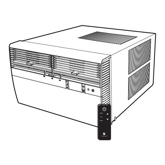
- Page 1 Kuhl Series ® Room Air Conditioners Q Chassis Models Using R-32 Refrigerant Kühl KCQ08B10A 115-Volt: THE EXPERTS IN ROOM AIR CONDITIONING 92000022_00...
-
Page 2: Table Of Contents
Register your Air Conditioner Model information can be found on the name plate. Please complete and mail the owner registration card fur- nished with this product, or register online at www.friedrich. com. For your future convenience, record the model information in Section R, information for the owner. -
Page 3: Important Safety And General Information
A. IMPORTANT SAFETY AND GENERAL INFORMATION A.1 Introduction This booklet contains the installation and operating instructions for your Air Conditioning unit. There are some precautions that should be taken to ensure proper operation. Improper installation can result in unsatisfactory operation or dangerous conditions. Read this booklet and any instructions packaged with separate equipment required to make up the system prior to installation. - Page 4 CAUTION: Do Not Operate Equipment During Active Stages Of Construction To ensure proper operation, Friedrich requires that all equipment is not operated during active construction phases. This includes active stages of completing framing, drywalling, spackling, sanding, painting, flooring, and moulding in the equipment’s designated conditioning space. The use of this equipment during construction could result in premature failure of the components and/or system and is in violation of our standard warranty guidelines.
-
Page 5: Unpacking Instructions
A. IMPORTANT SAFETY AND GENERAL INFORMATION A.4.1 Unpacking Instructions STEP 1. Cut all 4 packing straps. STEP 2. Slowly remove outer box, careful not to loosen decorative front. STEP 3. Remove upper cover. STEP 4. Remove 4 corner angles. STEP 5. Remove base carton. STEP 1 STRAPS x4 STEP 2... -
Page 6: Importance Of A Quality Installation
Opening of any ventilated Any tubing or refrigerant circuit work Opening of any sealed components Enclosures beyond the hinged door for filter cleaning Scan this QR code to be linked to the Friedrich professional support page where you can locate the Service Manual. -
Page 7: Packing List
A. IMPORTANT SAFETY AND GENERAL INFORMATION A.6 Packing List Installation Hardware Installation Hardware ITEM DESCRIPTION QTY. ITEM DESCRIPTION QTY. Q KÜHL UNIT SCREW #8 x ½" (BLUE BAG) Q SIDE CURTAINS (INCLUDES 8 PUSH PINS) SCREW #8 x 1 ¼" (GREY BAG) WINDOW SEAL GASKET SPARE PUSH PINS SHELL GASKET (ADHESIVE-BACK) -
Page 8: Product Data
Please note that Wireless Programming and Control: junction and electrical boxes are not acceptable for outdoor use. Friedrich Connect allows you to conveniently control, program, and monitor your air conditioning unit remotely from a smartphone or computer. Pre-Programmed Timer Options: Your unit’s digital control comes equipped with a 24-hour timer. -
Page 9: Installation Of The Unit
C. INSTALLATION OF THE UNIT C.1 Pre-Installation Checkpoints C.3. Choosing a Location Installation Clearances Before attempting any installation, carefully consider the Improper installation of the Air Conditioner can cause poor perfor- following points: mance and premature wear of the unit. Ensure that the KUHL unit is installed with proper clearances as •... -
Page 10: Window Installation
C. INSTALLATION OF THE UNIT C.4 Window Installation STEP 3. Once both curtains have been installed, slide hands underneath the WARNING unit to lift and carry to the window, as shown in Figure C.5.3. Obtain assistance as needed. Falling Object Hazard Not following Installation Instructions for mounting your air conditioner can result in property damage, injury, or... - Page 11 C. INSTALLATION OF THE UNIT C.4 Window Installation (Continued) STEP 4 Pull unit from sleeve, using the side handles located on either side of the decorative front. Obtain assistance as needed. Place unit out of the way on a secure, flat surface (Figure C.4.4). STEP 5 Place the sleeve in window with the bottom support rail up against the back edge of the window sill.
- Page 12 C. INSTALLATION OF THE UNIT C.4 Window Installation (Continued) STEP 8 Inspect unit prior to inserting back into sleeve. Manually rotate fan to STEP 10 Plug in unit. see that it turns freely. Make sure electrical cord is positioned in the Now that installation is complete, your unit is ready to operate! Simply plug in front of unit and out of the way when inserting it back into the sleeve.
- Page 13 C. INSTALLATION OF THE UNIT C.5 Thru-the Wall Installation STEP 2. Remove shell channel from top of the sleeve (Figure C.5.2). STEP 1. After removing the unit from shipping carton, slide chassis out of sleeve. Hold the cabinet stationary. Then, use the hand grips on both ends of the control unit support bracket to pull the chassis out of the NOTE: Not applicable to heat pump models sold without quick mounting...
- Page 14 C. INSTALLATION OF THE UNIT C.5 Thru-the Wall Installation (Cont.) STEP 5 Position the front edge to extend into the room " minimum at top of sleeve and 1" minimum at bottom (Figure C.5.4). STEP 6 Secure each side of the sleeve with supplied 1 ¼" screw (F in parts list) or nails through the holes in the sides.
- Page 15 C. INSTALLATION OF THE UNIT C.5 Thru-the Wall Installation (Cont.) STEP 9 Inspect unit prior to inserting back into sleeve. Manually rotate fan to STEP 10 Plug in unit. see that it turns freely. Make sure electrical cord is positioned in the Now that installation is complete, your unit is ready to operate! Simply plug in front of unit and out of the way when inserting it back into the sleeve.
- Page 16 C. INSTALLATION OF THE UNIT C.6 Cord Routing Change Unplug unit. WARNING Your Kühl Q unit will come with the power cord already installed and routed to the left side of the unit. For convenience and optimum appearance the direction of the power Electrical Shock Hazard cord can be changed from left to right by following the procedure Make sure your electrical receptacle has the...
- Page 17 Figure C.6.6 C. INSTALLATION OF THE UNIT C.6 Cord Routing Change CLOSE UP OF CORD UNDER LEFT MOUNTING SCREW EMBOSSMENT FACTORY SETTING WITH LEFT-SIDE CORD PLACEMENT Figure C.6.3 Figure C.6.5 NEW CORD ALIGNMENT FOR ROUTING CORD EXIT TO THE RIGHT OF UNIT Figure C.6.4...
-
Page 18: Install Filter
C. INSTALLATION OF THE UNIT C.7 Install Filter TOP TAB FRONT FRAME WITH STANDARD MESH FILTER Figure C.7.4 STEP 1. Swing the door open and remove the filter by grasping the filter grip and pushing the filter holder upward and outward. (See Figure C.7.2) STEP 2. -
Page 19: Electrical
E. ELECTRICAL Electrical Safety Information Testing the Power Cord All Friedrich room air conditioners are shipped from the factory with a Leakage Current Detection Interrupter (LCDI) equipped power WARNING cord. The LCDI device on the end of the cord meets the UL and NEC requirements for cord connected air conditioners. -
Page 20: Startup And Operation
J. STARTUP AND OPERATION Airflow direction adjustment The airflow path may be adjusted to distribute air independently from the left or right side of the discharge opening. Each of the banks of louvers can be directed left, right, up, or down in order to achieve the most optimum airflow positioning. To adjust airflow direction, grab the lever in the center of the louver bank and move it in the direction that you would like the air to be directed. -
Page 21: Control Panel Operation
J. STARTUP AND OPERATION J.3 Control Panel Operation Power On – Press the button to turn on the air conditioner. The power button illuminates to indicate that the power is on. The backlight on the power switch will automatically turn off after 20 seconds of inactivity. Display –... - Page 22 J. STARTUP AND OPERATION J.3 Control Panel Operation Accessing Sub-Menus The MENU button accesses the sub-menu. See Figure J.3.3. The arrow buttons navigate the 6 menu options See Figure J.3.4: – LIM – LOCK – TM – CnCT – F-C –...
- Page 23 J. STARTUP AND OPERATION J.3 Control Panel Operation Navigating Inside the Sub-Menus The MENU button moves you forward through the sub-menu. See Figure J.3.6. The RETURN button moves you backward once inside the LIM and TM menus. See Figure J.3.7. Figure J.3.6 MENU...
- Page 24 J. STARTUP AND OPERATION J.3 Control Panel Operation The LIM Menu Then you can set the higher setpoint limit using the arrow buttons. This is the limit menu. See Figure J.3.8. See Figure J.3.10. Upon entering the menu, the first option will be to set the lower setpoint limit using the arrow buttons.
- Page 25 J. STARTUP AND OPERATION J.3 Control Panel Operation Using the button, you switch to the minutes and complete setting the The TM Menu time. See Figure J.3.14. This is the TM menu used to set a timer. See Figure J.3.12. You select your mode.
- Page 26 J. STARTUP AND OPERATION J.3 Control Panel Operation The TM Menu continued Auto mode selected. See Figure J.3.16. Note: The auto mode timer sets both the cool and heat setpoint. Set the cool setpoint for your first timer period using the arrow buttons. Set the time to start the first timer period.
- Page 27 J. STARTUP AND OPERATION J.3 Control Panel Operation The TM Menu continued Set the cool setpoint for the second scheduled timer. See Figure J.3.20. Set the heat setpoint for the second timer. Set the time to start the second timer period. See Figure J.3.21. Press the button to complete the time timer setup.
- Page 28 J. STARTUP AND OPERATION J.3 Control Panel Operation The F-C Menu This menu is used to toggle between Fahrenheit and Celsius. This is the Fahrenheit/ Celsius Menu. See Figure J.3.23 Using the arrow buttons on the right side switches it from Fahrenheit to Celsius.
- Page 29 J. STARTUP AND OPERATION J.3 Control Panel Operation The Lock Menu This menu is used to lock the changing setting with a password. This is LOCK on. See Figure J.3.28. This is the Lock Menu. See Figure J.3.26. Set the first digit of the password using the arrow buttons. Use the button to proceed to the next digit.
- Page 30 J. STARTUP AND OPERATION J.3 Control Panel Operation The Lock Menu continued Set the second digit of the password using the same method. Set the fourth digit of the password using the same method. See Figure J.3.30 See Figures J.3.32 Set the third digit of the password using the same method.
- Page 31 J. STARTUP AND OPERATION J.3 Control Panel Operation The Lock Menu continued The ON on the right side of the display shows the lock function is Entering the correct password will give the user access to all of the sub- active.
- Page 32 J. STARTUP AND OPERATION J.3 Control Panel Operation The CnCT Menu This menu is used to turn on Wi-Fi connection. This is the CnCT menu. Pressing the button will activate Wi-Fi. See Figure J.3.38 The Wi-Fi symbol in the top right corner of the display shows Wi-Fi connection is on.
- Page 33 J. STARTUP AND OPERATION J.3 Control Panel Operation The diAG Menu This menu is used to access the diagnostic codes. See Figure J.3.40. Selecting this sub-menu shows the E that represents “Error.” See Figure J.3.41 Toggle through the error codes using the arrow keys. See Figure J.3.42 Figure J.3.40 MENU...
-
Page 34: Remote Control Operation
Noises operation. When the FAN SPEED button is pressed, the fan speed icon (triangle) All air conditioners make some noise. Friedrich units are designed to changes to indicate the new speed level. Fan speed automatically varies depending operate as quietly as possible. An air conditioner mounted in a wall is on the set temperature on the control panel and the actual room temperature. -
Page 35: Troubleshooting
M. TROUBLESHOOTING M.1. Troubleshooting Tips COMPLAINT CAUSE SOLUTION • • The unit is turned to the off position, or the Turn the unit to the on position and raise or lower temperature thermostat is satisfied. setting (as appropriate) to call for operation. •... -
Page 36: Troubleshooting Tips (Cont)
KWIKL – For all KEL and KHL models. Carbon Filter Kits See www.friedrich.com for additional accessories for your unit. The kits vary depending on the chassis size (small, medium, large). Each kit contains three (3) filters. -
Page 37: Information For The Owner
Area Required Area Required Authorized Friedrich Warranty Service Company in the area for 100 - 150 5000 550 - 700 14000 future reference if necessary. Inspect the unit for any damage to the coils and tubing that could cause a leak. -
Page 38: Warranty
R. INFORMATION FOR THE OWNER R.3 Warranty...
Need help?
Do you have a question about the Kuhl KCQ08 and is the answer not in the manual?
Questions and answers