Table of Contents
Advertisement
Quick Links
GBA C 6201 7 E
Instructions for Use
Multifunctional well Hot-Cold
Built-in unit ready to plug-in
Model-No. Art. No.
CW 330
C 6201
CW 660
C 6202
CW 990
C 6203
CW 660/2
C 6223
CW 990/3
C 6212
Scholl Apparatebau GmbH & Co. KG
Zinhainer Weg 4
D–56470 Bad Marienberg/Germany
+0049 (0) 2661 – 9868-10
Phone
+0049 (0) 2661 – 9868-38 (Service)
Fax
Internet
www.scholl-gastro.de
E-mail
info@scholl-gastro.de
BA
Last revised 03-2022
Built-in unit for central cooling system
Model-No. Art. No.
CWZ 330
C 6204
CWZ 660
C 6205
CWZ 990
C 6206
CWZ 660/2 C 6234
CWZ 990/3 C 6235
Page 1 of 26
März 9, 2022
Rev. 7
Advertisement
Table of Contents

Related Manuals for Scholl CW 330


Summary of Contents for Scholl CW 330
- Page 1 CW 660/2 C 6223 CWZ 660/2 C 6234 CW 990/3 C 6212 CWZ 990/3 C 6235 Scholl Apparatebau GmbH & Co. KG Zinhainer Weg 4 D–56470 Bad Marienberg/Germany +0049 (0) 2661 – 9868-10 Phone +0049 (0) 2661 – 9868-38 (Service) Internet www.scholl-gastro.de...
-
Page 2: Table Of Contents
GBA C 6201 7 E ABLE OF CONTENTS Table of contents ............................... 2 Preface ................................4 General ..............................5 Information about the user manual ....................5 Liability and warranty........................5 Copyright ............................5 Declaration of Conformity........................ 6 Safety ................................. 7 General ............................. - Page 3 GBA C 6201 7 E 5.2.1 Installation of the Multifunctional well ..................15 5.2.2 Electrical connections ........................ 16 Operation ............................16 5.3.1 Control panel ..........................17 Cleaning and maintenance ........................18 Safety instructions for cleaning...................... 18 Cleaning............................18 Safety instructions for maintenance ....................19 Maintenance ..........................
-
Page 4: Preface
REFACE Congratulations! In purchasing this new SCHOLL appliance you have chosen a product which meets highest technical stand- ards while providing outstanding convenience in practical use. This appliance has been designed with minimal energy consumption in mind. Used responsibly, it will serve you well in an ecologically sound manner. -
Page 5: General
GBA C 6201 7 E ENERAL NFORMATION ABOUT THE USER MANUAL This user manual describes the installation, operation and maintenance of the device and serves as an im- portant source of information and reference. The knowledge of all safety and handling instructions contained in the user manual creates the conditions for the safe and proper operation of this device. -
Page 6: Declaration Of Conformity
GBA C 6201 7 E ECLARATION OF ONFORMITY The device corresponds to the latest standards and EU directives. We certify this in the EC Declaration of Conformity. Page 6 of 26 März 9, 2022 Last revised 03-2022 Rev. 7... -
Page 7: Safety
GBA C 6201 7 E AFETY This section provides an overview of all-important safety aspects. In addition, each chapter provides precise safety instructions for the prevention of dangers which are marked with symbols. Moreover, the pictograms, signs and labels found on the device are to be observed and kept in legible condition. -
Page 8: Intended Use
GBA C 6201 7 E NTENDED USE The reliability of the device is only guaranteed if used properly in accordance with the specifications in the user manual. Any technical interventions, assembly and maintenance are to be made by qualified service personnel. The multifunctional well is for keeping dishes warm or cool (not for warming or cooling) of prepared dishes. -
Page 9: Transport, Packaging And Storage
GBA C 6201 7 E RANSPORT PACKAGING AND STORAGE RANSPORT INSPECTION The delivery must be checked immediately upon receipt for completeness and transport damage. In case of visible transport damage, do not accept the delivery, or only do so conditionally. The extent of the damage on the transport has to be marked on the documents/delivery note. -
Page 10: Technical Data
GBA C 6201 7 E ECHNICAL DATA ECHNICAL SPECIFICATIONS Built-in unit Multifunctional well Hot-Cold, temperature continuously adjustable Model-No. CW 330 CW 660 CW 990 Art.-No. C 6201 C 6202 C 6203 Casing CNS 18/10 CNS 18/10 CNS 18/10 GN size... - Page 11 GBA C 6201 7 E Built-in unit Multifunctional well Hot-Cold for central cooling system, temperature continuously adjustable Model-No. CWZ 330 CWZ 660 CWZ 990 Art.-No. C 6204 C 6205 C 6206 Casing CNS 18/10 CNS 18/10 CNS 18/10 GN size 1 x 1/1 - 100 2 x 1/1 - 100 3 x 1/1 - 100...
-
Page 12: Product Diagram
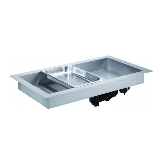
GBA C 6201 7 E RODUCT DIAGRAM 4.2.1 M ULTIFUNCTIONAL WELL OLD BUILT IN UNIT TEMPERATURE CONTINUOUSLY ADJUSTABLE Figure size 1 x 1/1 GN 4.2.2 M ULTIFUNCTIONAL WELL OLD BUILT IN UNIT FOR CENTRAL COOLING SYSTEM TEMPERATURE CONTINUOUSLY ADJUSTABLE Figure size 1 x 1/1 GN Page 12 of 26 März 9, 2022 Last revised 03-2022... -
Page 13: Multifunctional Well Hot-Cold Built-In Unit Temperature Separately Adjustable
GBA C 6201 7 E 4.2.3 M ULTIFUNCTIONAL WELL OLD BUILT IN UNIT TEMPERATURE SEPARATELY ADJUSTABLE Figure size 2 x 1/1 GN 4.2.4 M ULTIFUNCTIONAL WELL OLD BUILT IN UNIT FOR CENTRAL COOLING SYSTEM TEMPERATURE SEPARATELY ADJUSTABLE Figure size 2 x 1/1 GN Page 13 of 26 März 9, 2022 Last revised 03-2022... -
Page 14: Installation And Operation
GBA C 6201 7 E NSTALLATION AND OPERATION AFETY INFORMATION WARNING! Risk of electrocution! The device must be installed by qualified professionals. • Device may cause injuries due to improper installation! • Before installation, check the data of the local power grid with the technical specifications of the unit (see nameplate). -
Page 15: Installation And Electric Connection
GBA C 6201 7 E NSTALLATION AND ELECTRIC CONNECTION 5.2.1 I NSTALLATION OF THE ULTIFUNCTIONAL WELL • Put your device on a level and safe surface which stands the weight of the device. • Prepare the cut-out of the table according to our installation drawings and check the cut-out. •... -
Page 16: Electrical Connections
GBA C 6201 7 E 5.2.2 E LECTRICAL CONNECTIONS • The socket circuit must be secured according to the performance details. • Connect the controller to the circuit board. • Plug the Schuko plug into the socket. Figure only for the following devices: C 6201, C 6202, C 6203 PERATION •... -
Page 17: Control Panel
GBA C 6201 7 E 5.3.1 C ONTROL PANEL The multifunctional well can be set and operated via the touch control panel mounted on the front. The five buttons are used for adjusting settings, switching (between heating or cooling mode), quick choice between preset values, as well as parameterization. -
Page 18: Cleaning And Maintenance
GBA C 6201 7 E LEANING AND MAINTENANCE AFETY INSTRUCTIONS FOR CLEANING • Before cleaning and before repairing, disconnect the device from the outlet (pull the plug!) and al- low it cool. • Do not use caustic cleaning agents and make sure that no water seeps into the device. •... -
Page 19: Safety Instructions For Maintenance
GBA C 6201 7 E AFETY INSTRUCTIONS FOR MAINTENANCE • Check the main cable for damage from time to time. Do not use the device if the cable is damaged. If the cable is damaged, it must be replaced by customer service or a qualified electrician to avoid risks. -
Page 20: Possible Malfunctions
GBA C 6201 7 E OSSIBLE MALFUNCTIONS Problem Cause Remedy • Power plug not plugged in • Pull out the plug and insert it properly correctly • Fuse of the power supply has • Check fuse, test unit on a differ- No function tripped ent elec. -
Page 21: Disposal
GBA C 6201 7 E ISPOSAL Old equipment Your old device must be disposed of at the end of its service life in accordance with local regulations. It is advisable to contact a specialised waste management company, or to contact the local disposal service in your community. -
Page 22: Installation Drawings
ULTIFUNCTIONAL WELL Model-No Art.-No. GN size Cut-out size Installation Well worktop height CW 330 C 6201 1 x 1/1 - 100 375 x 580 mm 250 mm continuously 2 x 1/1 – 100 CW 660 C 6202 720 x 580 mm... -
Page 23: Temperature Controller Multifunctional Well
GBA C 6201 7 E EMPERATURE CONTROLLER MULTIFUNCTIONAL WELL Dimensions Cut-out size Page 23 of 26 März 9, 2022 Last revised 03-2022 Rev. 7... -
Page 24: Circuit Diagrams
GBA C 6201 7 E IRCUIT DIAGRAMS Circuit diagrams are available upon request. 10.1 I NSTALLATION DIAGRAM CIRCUIT BOARD Figure only for the following devices: C 6201, C 6202, C 6203 Page 24 of 26 März 9, 2022 Last revised 03-2022 Rev. -
Page 25: Warranty And Service
GBA C 6201 7 E ARRANTY AND SERVICE 11.1 W ARRANTY CONDITIONS The manufacturer accepts no liability or warranty in the following cases: ➢ failure to observe notes and instructions given in the Instructions for Use; ➢ use of the product in a manner not conforming to its intended use; ➢... -
Page 26: Service Address
7:00 a.m. till 4:00 p.m. Fridays from 7:00 a.m. till 12:15 p.m. Outside these office hours please communicate your requests per e-mail or telefax. Scholl Apparatebau GmbH & Co. KG Zinhainer Weg 4 D-56470 Bad Marienberg/Germany Phone 0049 (0)2661/9868-10... - Page 27 1. Übersicht Zuleitung + Wago Klemmen =Schweiz Zuleitung Platine ZUL_PCB_PE MV1_PCB_PE Magnetventil Platine 1 / 6.2 MV2_PCB_PE Magnetventil Platine 2 / 6.4 Max. Vorsicherung 16A Erdung 4-L Endklemme grün-gelb Wago264 81009006 Zul. mit Schweiz-St. ger. 3x1,5 3,0m SW 81006035 Magnetventil Platine 3 MV3_PCB_PE MV1_PE Magnetventil 1...
- Page 28 2. Übersicht Regler =Kalt Warm Regler 230V Warm Regler 230V 81001003 81001003 Artikel Nummer: 16 620 000 16A (ohmsch.) 16A (ohmsch.) 6A (induk.) 6A (induk.) 250V AC 250V AC Fühler 1 Fühler 1 Heizung/ Heizung/ Kompressor Kompressor =Kalt-Warm Kalt-Warm Regler 230V Kalt-Warm Regler 230V 81001001 81001001...
- Page 29 2.a Übersicht Regler/Stecker R1_1 R1_2 R1_3 R1_4 R1_5 R1_6 R2_1 R2_2 R2_3 R2_4 R2_5 R2_6 =2xGN1 Artikel Nummer: 14 620 000 16 620 000 81006009 81006008 81006009 81006008 Kabel 2x0,50mm² L=1250mm grau Kabel 4x1,5mm² L=1250mm grau Kabel 2x0,50mm² L=1250mm grau Kabel 4x1,5mm²...
- Page 30 3. Übersicht Kompressor + Lüfter PSU_L KOM_PCB_L -X23 Kompressor 4-L Mittelklemme orange Wago264 81009005 KOM_PE KOM_N -W12-M1 -W13-M2 -W14-M3 Zuleitung Kompressor 3x1,5mm² L=500mm weiß Vorkonfektioniert Vorkonfektioniert 81006006 GNYE -M1.1 Kompressorsteuerung 81009001 Steuerung Kompressor DLE7.5CN 230V 82001003 81004003 81004003 Kompressor DLE7.5CN Ventilator 12V DC 80x80x25 stark Ventilator 12V DC 80x80x25 stark Kompressor...
- Page 31 4. Übersicht Heizung Heizung 1 Heizung 2 Heizung 3 H1_N H1_L H2_L H3_N H3_L H2_N 2.a.2 2.a.5 2.a.8 -X26 -X24 -X25 Heizung 1 Heizung 2 Heizung 3 2-L Mittelklemme lichtgrau Wago264 2-L Mittelklemme lichtgrau Wago264 2-L Mittelklemme lichtgrau Wago264 81009013 81009013 81009013 -W15-R1...
- Page 32 5. Übersicht Magnetventil Magnetventil 1 Magnetventil 2 Magnetventil 3 MV1_R_L MV1_PCB_L MV2_R_L MV2_PCB_L MV3_R_L MV3_PCB_L 2.a.4 2.a.1 2.a.7 -X27 -X28 -X29 Magnetventil Magnetventil Magnetventil 4-L Mittelklemme lichtgrau Wago264 4-L Mittelklemme lichtgrau Wago264 4-L Mittelklemme lichtgrau Wago264 81009034 81009034 81009034 MV1_PE MV1_N MV2_PE MV2_N...
- Page 33 6. Übersicht Relais + Netzteil MV1_PCB_PE MV1_PCB_N MV1_PCB_L MV2_PCB_PE MV2_PCB_N MV2_PCB_L MV3_PCB_PE MV3_PCB_N MV3_PCB_L -W21 -W22 -W23 -W24 -W25 -W26 -W27 -W28 -W29 81006020 81006023 81006020 81006021 81006023 81006020 81006021 81006023 81006021 1x1,5mm² 1x1,5mm² 1x1,5mm² 1x1,5mm² 1x1,5mm² 1x1,5mm² 1x1,5mm² 1x1,5mm² 1x1,5mm²...
- Page 34 7. Übersicht Fühler F1_L F1_N F2_L F2_N F3_L F3_N 2.a.3 2.a.3 2.a.9 2.a.6 2.a.9 2.a.6 -W35-B1 -W36-B2 -W37-B3 -W38-B4 -W39-B5 -W40-B6 Vorkonfektioniert Vorkonfektioniert Vorkonfektioniert Vorkonfektioniert Vorkonfektioniert Vorkonfektioniert =3xGN1 Artikel Nummer: 14 630 000 16 630 000 Fühler mit Anschraublasche 1xPt100 Fühler mit Anschraublasche 1xPt100 Fühler mit Anschraublasche 1xPt100 Fühler mit Anschraublasche 1xPt100...
- Page 35 1. Übersicht Zuleitung + Wago Klemmen =Schweiz MV1_PE Magnetventil 1 / 4.2 MV2_PE Magnetventil 2 / 4.4 Max. Vorsicherung 16A Erdung 4-L Endklemme grün-gelb Wago264 81009006 Zul. mit Schweiz-St. ger. 3x1,5 3,0m SW 81006035 MV3_PE Magnetventil 3 / 4.6 Erdung =England 4-L Endklemme grün-gelb Wago264 81009006...
- Page 36 2. Übersicht Regler =Kalt Warm Regler 230V Warm Regler 230V 81001003 81001003 Artikel Nummer: 16 620 000 16A (ohmsch.) 16A (ohmsch.) 6A (induk.) 6A (induk.) 250V AC 250V AC Fühler 1 Fühler 1 Heizung/ Heizung/ Kompressor Kompressor =Kalt-Warm Kalt-Warm Regler 230V Kalt-Warm Regler 230V 81001001 81001001...
- Page 37 2.a Übersicht Regler-Stecker R1_1 R1_2 R1_3 R1_4 R1_5 R1_6 R2_1 R2_2 R2_3 R2_4 R2_5 R2_6 =2xGN1 Artikel Nummer: 14 620 000 16 620 000 2xGN1 81006008 81006009 81006008 81006009 Kabel 4x1,5mm² L=1250mm grau Kabel 2x0,50mm² L=1250mm grau Kabel 4x1,5mm² L=1250mm grau Kabel 2x0,50mm²...
- Page 38 3. Übersicht Heizung Heizung 1 Heizung 2 Heizung 3 H3_L H1_N H1_L H2_N H2_L H3_N 2.a.2 2.a.5 2.a.8 Heizung 1 Heizung 2 Heizung 3 2-L Mittelklemme lichtgrau Wago264 2-L Mittelklemme lichtgrau Wago264 2-L Mittelklemme lichtgrau Wago264 81009013 81009013 81009013 -W1-R1 -W2-R2 -W3-R3 Vorkonfektioniert...
- Page 39 4. Übersicht Magnetventil Magnetventil 1 Magnetventil 2 Magnetventil 3 MV1_R_L MV2_R_L MV3_R_L 2.a.1 2.a.4 2.a.7 Magnetventil Magnetventil Magnetventil 4-L Mittelklemme lichtgrau Wago264 4-L Mittelklemme lichtgrau Wago264 4-L Mittelklemme lichtgrau Wago264 81009034 81009034 81009034 MV1_PE MV1_N MV2_PE MV2_N MV3_PE MV3_N -W4-K1 -W5-K2 -W6-K3 Kabel 3x1,5mm²...
- Page 40 6. Übersicht Fühler 2.a.3 2.a.3 2.a.6 2.a.6 2.a.9 2.a.9 F1_L F1_N F2_L F2_N F3_L F3_N -W17-B1 -W18-B2 -W19-B3 -?W2-B4 -W20-B5 -W21-B6 Vorkonfektioniert Vorkonfektioniert Vorkonfektioniert Vorkonfektioniert Vorkonfektioniert Vorkonfektioniert =3xGN1 Artikel Nummer: 14 630 000 16 630 000 Fühler mit Anschraublasche 1xPt100 Fühler mit Anschraublasche 1xPt100 Fühler mit Anschraublasche 1xPt100 Fühler mit Anschraublasche 1xPt100...
Need help?
Do you have a question about the CW 330 and is the answer not in the manual?
Questions and answers