Table of Contents
Advertisement
Quick Links
This document covers the mounting and wiring of the IO-R-34 module
for expanding an EC-BOS-8. It assumes that you are an engineer,
technician, or service person who is performing control system design
or installation. Please read through this entire document before
beginning the installation procedures.
Product Description
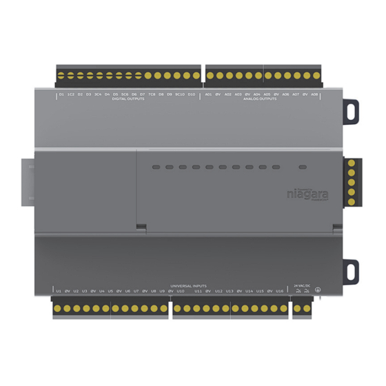
The IO-R-34 expands an EC-BOS-8
remotely located, including:
16 Universal Inputs (UIs) compatible with 0-10Vdc, 0-20mA, dry
•
contacts, pulsing dry contacts, 0-100K ohm resistive, or Type 3 thermistor temperature sensors.
10 Digital Outputs (DOs) with Form-A relay contacts for on/off control of loads up to 24Vac/dc, at 0.5A max.
•
8 Analog Outputs (AOs) for 0-10Vdc analog control of loads at 2.5K ohm minimum, or 4mA drain maximum.
•
The IO module uses DIN rail mounting and has two end-mounted 5-pin connectors that support direct-chaining
(in-line attachment) to IO-R-16 modules.
Communications to an EC-BOS-8 uses RS-485 multidrop on 3 wires of an end-mounted 5-pin connector. The other
two wires are for OUTPUT power (15 Vdc) used to power IO-R-16 modules. The IO-R-34 can provide power to up
to 4 attached IO-R-16 modules (if used). A two position connector is provided for primary power input to the module.
The RS-485 bus is wired back to Com 1 or Com 2 of the EC-BOS-8.
Related Documentation
For more information on mounting, wiring and configuring a system, refer to the EC-BOS-8 Mounting & Wiring
Guide, Remote IO-R-16 Mounting and Wiring Guide, and the NRIO Driver Guide.
System Planning
System planning requires consideration of options regarding power, RS-485 communications, mounting and wiring.
The following sections describe communications and power variables to consider before mounting and wiring your
hardware.
Number of Supported Expansion Modules
An EC-BOS-8 can support a maximum of 8 IO-R-34 modules OR a maximum of 16 IO-R-16 modules on a single
RS-485 bus. So, the IO-R-34 counts as two IO-R-16 modules. For example, the EC-BOS-8 could support 2 IO-R-34
modules and 12 IO-R-16 modules.
modules.
1. EC-BOS-8 with EC-Net 4.3 and later and an available RS-485 port.
See
"System Planning"
on page 1 for more details.
Niagara Framework is a trademark of Tridium, Inc.
Remote IO-R-34 Module Mounting and Wiring Guide
Remote IO-R-34 Module
Mounting and Wiring Guide
1
with 34 I/O points that can be
Table 1
shows possible options for combinations of IO-R-16 and IO-R-34
August 2, 2017
1
Advertisement
Table of Contents

Subscribe to Our Youtube Channel
Related Manuals for Distech Controls IO-R-16


Summary of Contents for Distech Controls IO-R-16
- Page 1 Communications to an EC-BOS-8 uses RS-485 multidrop on 3 wires of an end-mounted 5-pin connector. The other two wires are for OUTPUT power (15 Vdc) used to power IO-R-16 modules. The IO-R-34 can provide power to up to 4 attached IO-R-16 modules (if used). A two position connector is provided for primary power input to the module.
- Page 2 Option 9 IO-R-34 Both IO-R-16 and IO-R-34 should have a UPS power backup if continuous operation during power failures is a requirement. These modules do not support the battery powered configurations provided on some legacy hardware. The 5 pin power/comm connectors do not include a battery pin, preventing connection to (and possible damage from) legacy controllers.
-
Page 3: Included In This Package
22 to 26.4Vdc power supply capable of supplying at least 916mA (22 Watts). This is sufficient to power a – fully loaded IO-R-34 (4 IO-R-16 modules plus the IO-R-34). DIN rail, type NS35/7.5 (35mm x 7.5mm) and low-profile DIN rail end-clips (stop clips), recommended for •... -
Page 4: Safety Precautions
Connect S terminal wiring as shown in Figure 6 or communication errors may result. S terminal serves Caution as reference ground between isolated RS-485 ports on EC-BOS-8, IO-R-16 and IO-R-34 modules. Remote IO-R-34 Module Mounting and Wiring Guide August 2, 2017... -
Page 5: Weee (Waste Of Electrical And Electronic Equipment)
1). Rotate the module flush against the DIN rail and then press the locking clip upward to release it and secure the module to the rail. Slide the IO-R-34 module along the DIN rail to its intended location. If connecting to an IO-R-16 module, Step 3 seat the 5-position plug into that module’s connector socket. -
Page 6: Mounting On Din Rail
DIN rail clip both ends D5 5C6 D6 D7 7C8 D8 9C10 D10 AO1 0V AO2 AO3 0V AO4 0V AO6 0V AO8 IO-R-16 IO-R-16 IO-R-34 5-position connector plug with cabling to EC-BOS and other remote modules. 24Vac/24Vdc To remove an IO-R-34 module from a DIN rail, remove DIN rail end clips and (if applicable) slide it away Note from other modules. -
Page 7: Wiring Details
Connect S terminal wiring as shown in Figure 6 or communication errors may result. S terminal serves Caution as reference ground between isolated RS-485 ports on EC-BOS-8 and IO-R-16 and IO-R-34 modules. Apply power to the unit. See “Power up and Initial Checkout,” page 15. -
Page 8: Power Wiring
AWG or larger wire. Keep these wires as short as possible. Figure 4 for the location of the earth grounding wire for the IO-R-34. Figure 4 Earth ground connection required to the IO-R-34 module as well as IO-R-16 modules, if used. D5 5C6 D6 D7 7C8 D8 9C10 D10... - Page 9 RS-485 communications from the EC-BOS-8 to each IO module (or assembly of modules) requires a continuous “daisy-chain” wiring topology using a shielded, twisted-pair cable. Wire between the IO-R-16 assemblies using the 5-position end connectors. At the EC-BOS-8, wire to either of its 3-position RS-485 connectors.
- Page 10 Shielded twisted pair cabling D5 5C6 D6 D7 7C8 D8 9C10 D10 AO1 0V AO2 AO3 0V AO4 0V AO6 0V AO8 Add up to 4 IO-R-16 IO-R-16 IO-R-34 modules per IO-R-34 – One or more IO-R-34 D5 5C6 D6...
- Page 11 Wiring Details Inputs Figure 7 Thermistor wiring. U1 0V U2 U3 0V U4 Cut and tape shield wire back at Thermistor. 10K Thermistor Shielded, Twisted Cable, Stud in enclosure 61m (200 ft) maximum Shield Resistive 0-100K ohms The inputs can read a resistive signal within a range from 0 to 100,000 ohms. Wiring is the same as shown for a Thermistor temperature sensor (Figure Resistive signals require a ResistiveInputPoint.
-
Page 12: Binary Input
Wiring Details Inputs Figure 9 4 to 20 mA wiring. U1 0V U2 U3 0V U4 4—20 mA Sensor (self-powered sensor) Use point: VoltageInputPoint Cut and tape shield wire back at sensor. Range: 0—20 mA Conversion: 500 Ohm Shunt 499 Ohm resistor secondary conversion: Linear (supplied with unit) Shielded, Twisted Cable,... -
Page 13: Relay Outputs
Wiring Details Outputs Figure 10 Binary input wiring. U1 0V U2 U3 0V U4 Pulse Range: Up to 20 Hz, Cut and tape shield 50% Duty Cycle wire back at sensor. Minimum dwell time > 25ms Use point: CounterInputPoint Shielded, Twisted Cable, 61m (200 ft) maximum Stud in enclosure Shield... -
Page 14: Analog Outputs
NrioModule (Software) Representation NrioModule (Software) Representation Figure 11 Relay output wiring diagram. 24Vac Transformer Mains 24Vac Loads (see previous (Line) Warning) Use point: RelayOutputWritable 24Vdc Power 24Vdc Supply – D2 D3 Note that 15-position DO connector plug has 5 common terminals “C” (1–2, 3–4, 5–6, 7–8, 9–10), which are isolated from each other. -
Page 15: Power Up And Initial Checkout
Power up and Initial Checkout Power up and Initial Checkout After a remote I/O module is discovered and added to the station under this NrioNetwork (each one as an Note Nrio34Module), the serial status LEDs for the EC-BOS’s RS-485 port continually flash, reflecting polling activity. -
Page 16: Standard Replacement Parts
Replacement Parts Replacement Parts Replacement Parts Servicing the IO-R-34 may call for replacement parts. There are two categories of parts: Standard Replacement Parts • New Replacement Units • Standard Replacement Parts Standard replacement parts are listed in Table 2 and can be ordered from stock without restriction. Standard replacement parts cannot be returned for credit and should be disposed of in an appropriate manner. -
Page 17: Returning A Defective Unit
Replacement Parts Returning a Defective Unit Mount the replacement IO-R-34 as it was previously, using the same DIN rail location and/or screws. Step 6 Reconnect the earth ground wire to the module’s grounding lug. Step 7 Reconnect all I/O connectors to the IO-R-34. Step 8 If any of your I/O points have voltage, turn the devices back on, or reconnect power to them. - Page 18 ©, Distech Controls Inc., 2010 to 2015. All rights reserved. Images are simulated. While all efforts have been made to verify the accuracy of information in this manual, Distech Controls is not responsible for damages or claims arising from the use of this manual.
Need help?
Do you have a question about the IO-R-16 and is the answer not in the manual?
Questions and answers