Table of Contents
Advertisement
Quick Links
This document covers the mounting and wiring of a Remote I/O Module
(IO-R-16), for expanding an EC-BOS-8. It assumes that you are an engineer,
technician, or service person who is performing control system design or
installation. Please read through this entire document before beginning the
installation procedures.
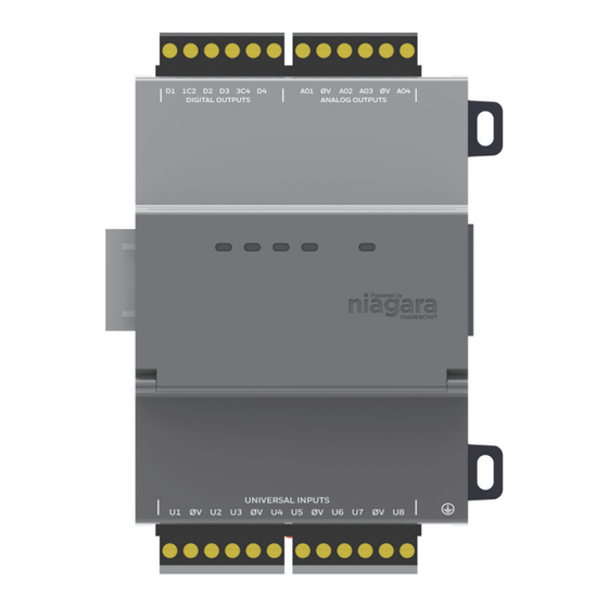
Product Description
The IO-R-16 expands an EC-BOS-8
located, including:
8 Universal inputs (UIs), compatible with 0–10Vdc, 0–20mA, dry contacts,
•
pulsing dry contacts, 0–100K ohm resistive, or Type 3 thermistor
temperature sensors.
4 Digital outputs with Form-A relay contacts, for on/off control of loads up
•
to 24Vac/dc, at 0.5A max.
4 Analog outputs (AOs) for 0–10Vdc analog control of loads at 2.5K ohm
•
minimum, or 4mA drain maximum.
The IO module uses DIN rail mounting and has two end-mounted 5-pin connectors that support direct-chaining
(in-line attachment) to other IO-R-16 modules or IO-R-34 modules.
Communications to an EC-BOS-8 use RS-485 multidrop on 3 wires of an end-mounted 5-pin connector. The other
2 wires on that connector are for INPUT power (15Vdc) which can be supplied from a DIN-mountable option
(IO-R-34) or a third party 13.5-15.75 Vdc power supply. The RS-485 bus is wired back to Com 1 or Com 2 of the
EC-BOS-8.
Related Documentation
For more information on mounting, wiring and configuring a system, refer to the EC-BOS-8 Mounting & Wiring
Guide, Remote IO-R-34 Mounting and Wiring Guide, and the NRIO Guide.
System Planning
System planning requires consideration of options regarding power, RS-485 communications, mounting and wiring.
The following sections describe communications and power variables to consider before mounting and wiring your
hardware.
Number of Supported Expansion Modules
An EC-BOS-8 can support up to a maximum of 16 IO-R-16 modules via a single RS-485 bus. If an IO-R-34 is
included, the IO-R-34 counts as two modules. So, for example, the EC-BOS-8 could support 2 IO-R-34 modules and
12 IO-R-16 modules.
Table 1
Power Supply Options and Considerations
You can provide power to the IO-R-16 from the 5-pin connector of an IO-R-34. Each IO-R-34 module can power up
to 4 IO-R-16 modules. You can also use a third-party 13.5-15.75 Vdc power supply (output regulated to within ±4%)
wired to the P+ and P- terminals of an IO-R-16 module's 5-position end connector.
1. EC-BOS-8 with EC-Net 4.3 and later and an available RS-485 port.
See
"System Planning,"
page 1 for more details.
Niagara Framework is a trademark of Tridium, Inc.
Remote IO-R-16 Module Mounting and Wiring Guide
Remote IO-R-16 Module
Mounting and Wiring Guide
1
with 16 I/O points that can be remotely
shows possible options for combinations of IO-R-16 and IO-R-34 modules.
August 2, 2017
1
Advertisement
Table of Contents

Related Manuals for Distech Controls IO-R-16


Summary of Contents for Distech Controls IO-R-16
- Page 1 Number of Supported Expansion Modules An EC-BOS-8 can support up to a maximum of 16 IO-R-16 modules via a single RS-485 bus. If an IO-R-34 is included, the IO-R-34 counts as two modules. So, for example, the EC-BOS-8 could support 2 IO-R-34 modules and 12 IO-R-16 modules.
- Page 2 3. Operation without power backup If an IO-R-16 module is powered locally, with an IO-R-34, for example, and a momentary AC power loss occurs, note that a number of undesirable things can result, including: Load cycling from IO-R-16 relays dropping out, including several seconds lag to first re-establish •...
- Page 3 Note that each IO-R-16 draws (at most, when all four relays are pulled in) 0.133A, and thus can introduce voltage drop when long cabling distances are used for power/backup.
-
Page 4: Included In This Package
Be sure to heed these warnings to prevent personal injury or equipment damage. Warning • A 15Vdc circuit powers the IO-R-16 module. Disconnect power before installation or servicing to prevent electrical shock or equipment damage. • Make all connections in accordance with national and local electrical codes. Use copper conductors only. -
Page 5: Static Discharge Precautions
Use a wrist strap when handling PCBs, with the wrist strap clamp secured to earth ground. Module Connection Precautions Do not connect more than the maximum number of IO-R-16 modules to the RS-485 port of the parent Caution EC-BOS—note that 16 is the maximum number supported in software. However, less IO-R-16 modules may be supported. -
Page 6: Physical Mounting
Pull or pry down the plastic locking clip until it snaps into the open (down) position. Step 1 Position the IO-R-16 module on the rail, tilting to hook the top DIN rail tab over the upper edge of the DIN Step 2... -
Page 7: Mounting On Din Rail
EC-BOS and other remote modules. 24Vac/24Vdc To remove an IO-R-16 module from a DIN rail, remove DIN rail end clips and (if applicable) slide it away Note from other modules. Move the plastic locking tab down to open position then lift unit outwards. - Page 8 IO-R-16 Board Layout and Terminals IO-R-16 Board Layout and Terminals IO-R-16 Board Layout and Terminals The IO-R-16 module provides 8 universal inputs, 4 digital relay outputs, and 4 0–10Vdc analog outputs. Wiring terminal positions are shown below (Figure 3), along with LED locations.
-
Page 9: Wiring Details
“Grounding” section on page 9 for details. Wire the supply power to the IO-R-16, but do not energize the power source until all other wiring is completed. Depending on how you are powering the IO-R-16, methods differ: If powering the IO-R-16 from an IO-R-34, slide the two modules together to mate the connectors. - Page 10 IO-R-34 24Vac/24Vdc In some cases, some number of IO-R-16 modules may be powered this way (from IO-R-34), while others may be powered locally using a third-party 13.5-15.75 Vdc power supply. This may be advisable when IO modules are located long distances from the IO-R-34 providing power, to avoid excessive voltage drops due to wiring resistances.
- Page 11 Power supply models furnishing 15Vdc output are the most commonly available. • Only remote IO-R-16 modules can be powered by a 15Vdc power supply—the EC-BOS-8 and the • IO-R-34 requires 24Vdc. See the appropriate Mounting & Wiring Guide for details.
- Page 12 Wiring Details Inputs Figure 7 RS-485 wiring from the EC-BOS to one or more IO-R-16 modules uses a “daisy-chain” connection. EC-BOS-8 RS-485 Port Connect RS-485 shield Shielded twisted pair cabling wire to ground at one end only. Terminals on the 5-position...
- Page 13 4–20 mA sensors. Input accuracy is ±2% of span, without user calibration. Figure 10 shows the wiring diagram, which requires a 499 ohm resistor wired across the input terminals. 4–20 mA sensors also require the VoltageInputPoint. Remote IO-R-16 Module Mounting and Wiring Guide August 2, 2017...
-
Page 14: Binary Input
Caution making or changing any wiring connections to the IO-R-16 module. This is in addition to removing power from the IO-R-16 module. It is important to not apply external power to the UI inputs without the 499 ohm resistor in place. -
Page 15: Relay Outputs
Use point: BooleanInputPoint Shielded, Twisted Cable, 61m (200 ft) maximum Stud in enclosure Shield Outputs A IO-R-16 module has four (4) digital relay outputs and four (4) 0–10 volt analog outputs. Relay Outputs Each relay output is rated at 24 Vac or Vdc at 0.5A. Relay outputs have MOV (metal oxide varistor) suppressors to support inductive-type loads such as heavy-duty relay coils. -
Page 16: Analog Outputs
AO1 0V AO2 AO3 0V AO4 Nrio16Module (Software) Representation In the EC-Net station interface to the EC-BOS and IO-R-16 module, the module’s I/O is modeled in the station’s NrioNetwork (copied from the nrio palette), under a child Nrio16Module “device level” component. This Nrio16Module has a default name of “io16_n”. -
Page 17: Power Up And Initial Checkout
To replace a faulty IO-R-16 unit, order and install a new IO-R-16 accessory module. If the faulty IO-R-16 is still in warranty, you can receive credit by returning it. Be sure to contact the vendor for a return material authorization (RMA) number before shipping an item for return credit. -
Page 18: Returning A Defective Unit
If any I/O points have voltage, turn the devices off or disconnect power to them. Note Note positions of all I/O wiring going to the IO-R-16 module to be replaced, as well as for any other Step 3 installed modules. If necessary, label connectors and accessory modules to avoid mis-connection later (after IO-R-16 is replaced). - Page 19 Replacement Parts and New Units Returning a Defective Unit Please provide: Product model • Nature of defect • PO number to secure the RMA • Remote IO-R-16 Module Mounting and Wiring Guide August 2, 2017...
- Page 20 ©, Distech Controls Inc., 2010 to 2015. All rights reserved. Images are simulated. While all efforts have been made to verify the accuracy of information in this manual, Distech Controls is not responsible for damages or claims arising from the use of this manual.
Need help?
Do you have a question about the IO-R-16 and is the answer not in the manual?
Questions and answers