Table of Contents
Advertisement
Quick Links
SC-ARES
Analog Resistance Module
Product Description
This document describes the hardware installation procedures for the SC-ARES Analog Resistance Module.
The analog resistance module is an interface that accepts an analog signal input (voltage or current) and uses that signal to proportionally control a variable
resistance output. The device output simulates a 3 wire slide wire or rotary potentiometer. The resistive output is electrically isolated from the input control
signal.
The input signal type is DIP switch selectable to one of several factory calibrated standard ranges and the output has both ends of the potentiometer and
the wiper available on the terminal connectors. The output resistance simulates a potentiometer and does not wrap around at the end points.
The resistance module includes a regulated power output that can be used to power a current-loop transducer and also features a failsafe input that will
connect to the output terminals in case of power loss or for manual output control. There is also an LED power indicator and a manual override jumper for
failsafe operation.
The product comes with standard snap-track for easy mounting or is available with various resistance values. The potentiometer may be ordered with no
offset value such as 0-135 Ω, or may be configured with an offset resistance such as 20-30K Ω.
General Installation Requirements
For proper installation and subsequent operation of each device, pay special attention to the following recommendations:
-
Upon unpacking the product, inspect the contents of the carton for shipping damages. Do not install damaged device.
-
Avoid areas where corroding, deteriorating or explosive vapors, fumes or gases may be present.
-
Ensure that all equipment is installed according to local, regional, and national regulations.
Personal injury or loss of life may occur if you do not follow a procedure as specified.
Equipment damage or loss of data may occur if you do not follow a procedure as specified.
Take reasonable precautions to prevent electrostatic discharges to the controller when installing, servicing or operating
the controller. Discharge accumulated static electricity by touching one's hand to a well-grounded object before working
with the controller.
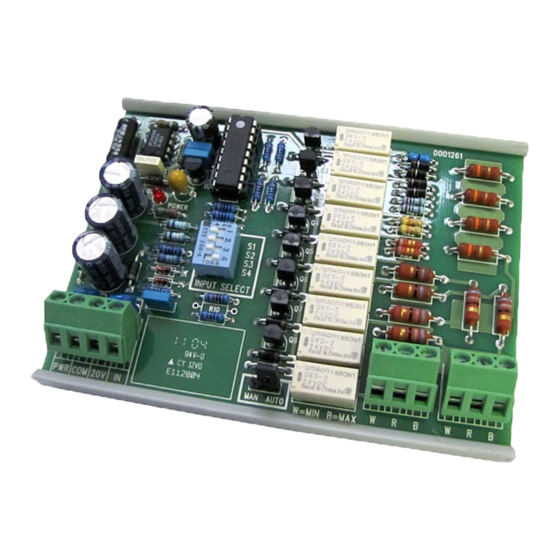
Figure 1: SC-ARES Analog Resistance Module
I n s t a l l a t i o n G u i d e
Advertisement
Table of Contents

Related Manuals for Distech Controls SC-ARES


Summary of Contents for Distech Controls SC-ARES
- Page 1 Product Description This document describes the hardware installation procedures for the SC-ARES Analog Resistance Module. The analog resistance module is an interface that accepts an analog signal input (voltage or current) and uses that signal to proportionally control a variable resistance output.
- Page 2 Mounting Instructions The snap-track device may be mounted in any position. Use only fingers to remove the PCB from the snap-track, do not pry on the PCB with tools. Do not flex the PCB during removal or installation. Slide the PCB out of the snap-track or push against one side of the snap-track and lift the PCB out. See Figure 2.
- Page 3 Wiring Deactivate the 24 Vac power supply until all connections are made to the device to prevent electrical shock or equipment damage. Follow proper electrostatic discharge handling procedures when installing the device or equipment damage may occur. Use 22 AWG shielded wiring for all connections and do not locate the device wires in the same conduit with wiring used to supply inductive loads such as motors.
- Page 4 Operation – Input and Output Signals The input signal type is selected with the 4 position DIP switch labeled INPUT SELECT. The available input signal types and DIP switch positions are shown in the chart below. Figure 6 Input and Output Signals Figure 7 Applications of Operation Input Output Signals The ranges shown in the chart are all pre-calibrated such that 0-100% of the input signal will cause the output resistance from W to R to change from the pot minimum to the maximum value.
- Page 5 ©, Distech Controls 2020 All rights reserved. While all efforts have been made to verify the accuracy of information in this manual, Distech Controls is not responsible for damages or claims arising from the use of this manual. Persons using this manual are assumed to be trained HVAC specialist / installers and are responsible for using the correct wiring procedures and maintaining safe working conditions with fail-safe environments.
Need help?
Do you have a question about the SC-ARES and is the answer not in the manual?
Questions and answers