
Related Manuals for Retsch BB50


Summary of Contents for Retsch BB50
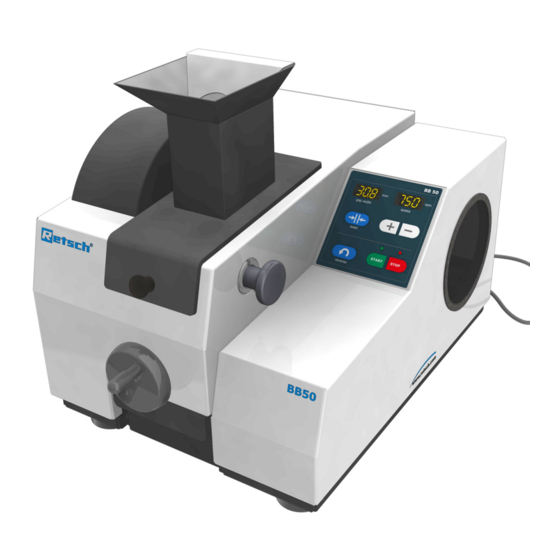
- Page 1 Manual Jaw Crusher BB50 Translation © Retsch GmbH, 42781 Haan, Retsch-Allee 1-5, Germany 07.02.2023 0004...
- Page 2 Copyright © Copyright by Retsch GmbH Haan, Retsch-Allee 1-5 D-42781 Haan Federal Republic of Germany...
-
Page 4: Table Of Contents
Notes on the Operating Manual ....................6 Explanations of the safety warnings ....................7 General safety instructions ........................ 8 Repairs ............................... 9 Confirmation ..........................10 Technical data ..........................11 Use of the machine for the intended purpose ................11 3.1.1 Properties of the grinding material ..................... - Page 5 Operating elements and displays ....................22 Overview Table of the Operating Elements and the Display............23 Switching On and Off ........................23 Setting the gap width to zero position .................... 23 Setting the gap width ........................24 Reverse grinding ..........................25 Setting the Speed ..........................
-
Page 6: Notes On The Operating Manual
This operating manual does not contain any repair instructions. If faults arise or repairs are necessary, please contact your supplier or get in touch with Retsch GmbH directly. Application technology information relating to samples to be processed is not included but can be read on the Internet on the respective device’s page at www.retsch.com. -
Page 7: Explanations Of The Safety Warnings
1.1 Explanations of the safety warnings In this Operating Manual we give you the following safety warnings Serious injury may result from failing to heed these safety warnings. We give you the following warnings and corresponding content. WARNING Type of danger / personal injury Source of danger –... -
Page 8: General Safety Instructions
All persons concerned with the machine in any form This machine is a modern, high performance product from Retsch GmbH and complies with the state of the art. Operational safety is given if the machine is handled for the intended purpose and attention is given to this technical documentation. -
Page 9: Repairs
1.3 Repairs This operating manual does not contain any repair instructions. For your own safety, repairs may only be carried out by Retsch GmbH or an authorized representative or by Retsch service engineers. In that case please inform: The Retsch representative in your country... -
Page 10: Confirmation
2 Confirmation This operating manual contains essential instructions for operating and maintaining the device which must be strictly observed. It is essential that they be read by the operator and by the qualified staff responsible for the device before the device is commissioned. This operating manual must be available and accessible at the place of use at all times. -
Page 11: Technical Data
The grinding of tough samples and/or large feed sizes with zirconium oxide (ZrO2) equipment may lead to material damage to the device. In such cases, consultation with the representative of Retsch GmbH in your country or directly with Retsch GmbH is recommended before grinding. 3.1.1 Properties of the grinding material In principle every hard and brittle grinding material with hardness grade >3 according to the... -
Page 12: Working Instructions
Technical data C1.0004 CAUTION Risk of explosion or fire Changing sample properties − The properties and therefore also the hazardousness of the sample can change during the grinding process. • Do not use any substances in this device which carry the risk of explosion or fire. -
Page 13: Protective Equipment
Technical data NOTICE If the crushing chamber (T) is filled with more than 2/3, then the fill hopper guide plates could be damaged; the moving breaker arm would force product behind the breaker arm and into the crusher housing. 3.3 Protective equipment Fig. -
Page 14: Receptacle Volume
Technical data 3.8 Receptacle volume The collection volume is < 3 l. 3.9 Feed size The maximum feed size is 40mm. 3.10 Rated power – 200-240 V: 1150W, 2 x 8A 3.11 Dimensions and weight When closed: Height: 463 mm Width: 421 mm Depth: 607 / 562 mm Weight: approx. -
Page 15: Transport, Scope Of Delivery, Installation
Transport, scope of delivery, installation 4 Transport, scope of delivery, installation 4.1 Packaging The packaging has been adapted to the mode of transport. It complies with the generally applicable packaging guidelines. NOTICE Storage of packaging – In the event of a complaint or return, your warranty claims may be endangered if the packaging is inadequate or the machine has not been secured correctly. -
Page 16: Electrical Connection
Transport, scope of delivery, installation Atmospheric humidity: Maximum relative humidity 80% at temperatures up to 31°C, decreasing linearly up to 50% relative humidity at 40°C NOTICE Atmospheric humidity – Electronic and mechanical components may be damaged and the performance data alter to an unknown extent. •... -
Page 17: Type Plate Description
Transport, scope of delivery, installation 4.6 Type plate description Fig. 4: Type plate 1 Device designation 2 Part number 3 Power version, Mains frequency 4 Fuse type and fuse strength 5 Capacity, Amperage 6 Year of production 7 Weight 8 Serial number 9 Bar code 10 Manufacturer’s address 11 UKCA marking... -
Page 18: Removing Transport Safeguards
Transport, scope of delivery, installation 4.7 Removing Transport Safeguards Fig. 5: Carrying the machine - preparation • Before installing the carry support, remove the hopper (B) and the grinding room cover (P). (see chapter Cleaning → removing the fill hopper / removing the splash-back protection) •... -
Page 19: Removing The Transport Safeguard
Transport, scope of delivery, installation 4.8 Removing the transport safeguard Fig. 7: Removing the transport lock The machine is secured by steel plates on both sides. • Remove the two screws (TS). • Pull the transport lock (TB) out sideways. 4.9 Installation of the machine Installation height: maximum 2000 m above sea level... -
Page 20: Operating The Machine
Operating the machine 5 Operating the machine 5.1 Views of the Instrument Fig. 8: Front view H,K,L Fig. 9: Rear view... -
Page 21: Overview Table Of The Parts Of The Device
Operating the machine Fig. 10: Machine partially open 5.2 Overview table of the parts of the device Element Description Function Splash-back protection Prevents sample ejection Fill hopper Receives the grinding material Release handle Releases the folding hopper Hand wheel with folding handle Setting the gap width... -
Page 22: Operating Elements And Displays
Operating the machine Drawer Receives the ground sample material Operator panel and display (see below) Bolt for front crusher arm Holds the front crusher arm On and off switch Disconnects the controller from or connects it to the mains. Machine fuse Overload protection. -
Page 23: Overview Table Of The Operating Elements And The Display
Operating the machine Fig. 11: View of the operator panel and displays 5.4 Overview Table of the Operating Elements and the Display Element Description Function Display of the gap width in mm Displays the gap width Display of the speed Number of crushing jaw lifts per minute Gap width zeroing Zero value setting on crushing jaw contact... -
Page 24: Setting The Gap Width
Operating the machine When aligning the gap width, the breaking jaws must not demonstrate any contact to each other when beginning the adjustment. • Before starting the machine, twist the hand wheel (D) 2 revolutions in an anti-clockwise direction. Fig. 13: Aligning the gap width •... -
Page 25: Reverse Grinding
Operating the machine Fig. 15: Gap width 5.8 Reverse grinding Fig. 16: Bridging effect in the grinding chamber Fig. 17: Reverse button Using the reverse function you can release grinding material in the event of a blockage in the machine or of bridging. •... -
Page 26: Setting The Speed
Operating the machine 5.9 Setting the Speed Fig. 18: Setting the speed • Switch the machine on at the main switch. The selectable grinding speed lies between 550 and 950 revolutions per minute • Briefly press button (F4 +) to increase the speed in increments of 50. •... -
Page 27: Stopping The Grinding Process
Operating the machine You can reduce the gap width (sw) with a twist of the hand wheel (D) in a clockwise direction. You can increase the gap width (sw) with a twist of the hand wheel (D) in an anti-clockwise direction. The values on the display (F1) specify the gap width in mm. -
Page 28: Safety Functions And Fault Display
Safety functions and fault display 6 Safety functions and fault display 6.1 Fault messages DESCRIPTION Switch machine off and back on. E 10 DRIVE OVERLOADED E 10 Where necessary wait 10 minutes E 22 ERROR KEYPAD E 22 Switch machine off and back on. Frequency converter is faulty. -
Page 29: Cleaning, Wear And Service
Cleaning, wear and service 7 Cleaning, wear and service 7.1 Cleaning WARNING Risk of a fatal electric shock An electric shock can cause injuries in the form of burns and cardiac arrhythmia, respiratory arrest or cardiac arrest. • Do not clean the blender under running water. Use only a cloth dampened with water. -
Page 30: Removing The Splash-Back Protection
Cleaning, wear and service 7.1.2 Removing the splash-back protection CAUTION 1.V0072 Risk of injury to eyes and skin Ejected sample material – Sample material can be ejected from the machine if the splash- back protection is missing. • Never operate the machine without the splash-back protection. -
Page 31: Replacing The Breaking Jaws
Cleaning, wear and service 7.2.1 Replacing the breaking jaws 7.2.2 Replacing the front breaking jaw NOTICE Zircon breaking jaws (ZB) are bonded across the entire surface (ZV). • Have the zircon breaking jaws replaced by an authorised service technician. Fig. 24: Bonding the zircon breaking jaws •... - Page 32 Cleaning, wear and service Fig. 26: Using the (bolt) removal tool • Pull the bolt (G) out of the guide. • Place the bolt (G) in the removal groove (Rn) of the front crusher arm. Fig. 27: Removing the breaking jaw •...
- Page 33 Cleaning, wear and service Fig. 28: Replacing the breaking jaw • Unscrew the two screws (RS). • Remove the retaining plate (RH) • Replace the breaking jaw (RB). Fig. 29: Screw securing adhesive • Use two new screws (RS) for installation or secure both screws with liquid screw securing adhesive (RL).
- Page 34 Cleaning, wear and service Fig. 30: Replacing the rear breaking jaw The rear breaking jaw is replaced directly in the machine. The rear crusher arm remains in the machine in the process. • Unscrew the two screws (RS). • Remove the retaining plate (RH) •...
-
Page 35: Wear
Cleaning, wear and service 7.3 Wear 7.3.1 Resetting the wear alert NOTICE After replacing the breaking jaws, the wear warning should be reset. Fig. 32: Wear alert The wear alert (F42) appears when the breaking jaws are worn. The currently set gap width flashes in the gap width (F1) display and the error code H43 is displayed in the speed (F2) display. -
Page 36: Disposal
Disposal 8 Disposal Please observe the respective statutory requirements with respect to disposal. Information on disposal of electrical and electronic machines in the European Community. Within the European Community the disposal of electrically operated devices is regulated by national provisions that are based on the EU Directive 2002/96/EC on Waste Electrical and Electronic Equipment (WEEE). -
Page 37: Index
9 Index 88.8/888 28 Fault messages 28 feed size 14 Feed size 14 Aligning the gap width 24 Front view 20 Ambient temperature 15 funnel-shaped 12 Amperage 17 Fuse strength 17 Atmospheric humidity 16 Fuse type 17 Bar code 17 Gap width 25 Bonding 31 General safety instructions 8... - Page 38 Part number 17 Setting the Speed 26 PLS 28 Starting the grinding process 26 Power version 17 Stopping the grinding process 27 property damage 7 Switching On and Off 23 Protective devices 13 Switch-on time 11 Protective equipment 13 Target group 8 Rated power 14 Technical data 11 Rear view 20...
- Page 41 © Retsch GmbH, 42781 Haan, Retsch-Allee 1-5, Germany 07.02.2023 0000...
- Page 44 Copyright ® Copyright by Retsch GmbH Haan, Retsch-Allee 1-5 D-42781 Haan Federal Republic of Germany...
Need help?
Do you have a question about the BB50 and is the answer not in the manual?
Questions and answers