Table of Contents
Advertisement
Quick Links
Advertisement
Table of Contents

Related Manuals for Supero SUPERSERVER 6017R-MTLF


Summary of Contents for Supero SUPERSERVER 6017R-MTLF
- Page 1 ® UPER UPER ERVER 6017R-MTLF Revision 1.0...
- Page 2 The information in this User’s Manual has been carefully reviewed and is believed to be accurate. The vendor assumes no responsibility for any inaccuracies that may be contained in this document, makes no commitment to update or to keep current the information in this manual, or to notify any person or organization of the updates.
- Page 3 SuperServer 6017R-MTLF. Installation and maintenance should be performed by experienced technicians only. The SuperServer 6017R-MTLF is a 1U rackmount server based on the SC- 813MFTQ-441CB server chassis and the Super X9DRL-EF serverboard. Please refer to our web site for updates on supported processors.
- Page 4 SUPERSERVER 6017R-MTLF User's Manual Chapter 5: Advanced Serverboard Setup Chapter 5 provides detailed information on the X9DRL-EF serverboard, including the locations and functions of connectors, headers and jumpers. Refer to this chapter when adding or removing processors or main memory and when reconfi guring the serverboard.
- Page 5 Preface Notes...
-
Page 6: Table Of Contents
SUPERSERVER 6017R-MTLF User's Manual Table of Contents Chapter 1 Introduction Overview ......................1-1 Serverboard Features ..................1-2 Processors ...................... 1-2 Memory ......................1-2 SATA ......................1-2 PCI Expansion Slots ..................1-2 I/O Ports ......................1-2 Server Chassis Features ................1-3 System Power .................... - Page 7 Table of Contents Chapter 3 System Interface Overview ......................3-1 Control Panel Buttons ..................3-1 Reset ....................... 3-1 Power ......................3-1 Control Panel LEDs ..................3-2 Information LED ....................3-2 NIC2 ........................ 3-2 NIC1 ........................ 3-2 HDD ......................... 3-2 Power ......................3-3 SATA Drive Carrier LEDs ................
- Page 8 SUPERSERVER 6017R-MTLF User's Manual Installing an LGA 2011 Processor ..............5-5 Installing a Passive CPU Heatsink ..............5-8 Removing the Heatsink ................... 5-8 Installing Memory Modules ................5-9 Installing & Removing DIMMs ................. 5-9 Memory Support ..................5-10 Populating Memory Slots ................. 5-10 Populating with UDIMM ECC/Non-ECC DIMMs ........
- Page 9 Table of Contents Explanation of Jumpers ................5-20 CMOS Clear ..................... 5-20 LAN1/LAN2 Enable/Disable ..............5-20 VGA Enable/Disable ................. 5-21 Watch Dog ....................5-21 BMC Enable .................... 5-21 C Bus to PCI/PCI-Exp. Slots ..............5-21 5-11 Onboard Indicators ..................5-22 LAN Port LEDs ..................
- Page 10 SUPERSERVER 6017R-MTLF User's Manual Advanced Setup Confi gurations..............7-3 Event Logs ....................7-24 IPMI ....................... 7-25 Boot ....................... 7-28 Security ......................7-29 Save & Exit ....................7-30 Appendix A BIOS Post Error Codes Appendix B System Specifi cations...
-
Page 11: Chapter 1 Introduction
Chapter 1 Introduction Overview The SuperServer 6017R-MTLF is comprised of two main subsystems: the SC- 813MFTQ-441CB 1U chassis and the X9DRL-EF serverboard. Please refer to our web site for information on operating systems that have been certifi ed for use with the SuperServer 6017R-MTLF (www.supermicro.com). -
Page 12: Serverboard Features
ERVER 6017R-MTLF User's Manual Serverboard Features At the heart of the SuperServer 6017R-MTLF lies the X9DRL-EF, a dual processor serverboard based on the Intel® PCH C602J chipset. Below are the main features of the X9DRL-EF. See Figure 1-1 for a block diagram of the chipset. -
Page 13: Server Chassis Features
The following is a general outline of the main features of the SC813MFTQ-441CB chassis. System Power When confi gured as a SuperServer 6017R-MTLF, the SC813MFTQ-441CB chassis includes a single 440W-480W power supply. SATA Subsystem The SC813MFTQ-441CB chassis was designed to support four SATA hard drives, which are hot-swappable units. - Page 14 UPER ERVER 6017R-MTLF User's Manual Figure 1-1. Intel C602J Chipset: System Block Diagram Note: This is a general block diagram. Please see Chapter 5 for details. 2208 CPU1 CPU0 Socket 01 Socket 00 E5-2600 E5-2600 Fan x6 NCT7904D PEG[7] PCI-E 2.0 x1 SATA GEN 3 PEG[1:4] PCI-E 2.0 x8(X4)
-
Page 15: Contacting Supermicro
Chapter 1: Introduction Contacting Supermicro Headquarters Address: Super Micro Computer, Inc. 980 Rock Ave. San Jose, CA 95131 U.S.A. Tel: +1 (408) 503-8000 Fax: +1 (408) 503-8008 Email: marketing@supermicro.com (General Information) support@supermicro.com (Technical Support) Web Site: www.supermicro.com Europe Address: Super Micro Computer B.V. Het Sterrenbeeld 28, 5215 ML 's-Hertogenbosch, The Netherlands Tel:... - Page 16 UPER ERVER 6017R-MTLF User's Manual Notes...
-
Page 17: Chapter 2 Server Installation
Preparing for Setup The box the SuperServer 6017R-MTLF was shipped in should include two sets of rail assemblies, six rail mounting brackets and the mounting screws you will need to install the system into the rack. Follow the steps in the order given to complete the installation process in a minimal amount of time. -
Page 18: Warnings And Precautions
UPER ERVER 6017R-MTLF User's Manual installation only in a Restricted Access Location (dedicated equipment rooms, service closets and the like). • This product is not suitable for use with visual display work place devices acccording to §2 of the the German Ordinance for Work with Visual Display Units. -
Page 19: Rack Mounting Considerations
Chapter 2: Server Installation Rack Mounting Considerations Ambient Operating Temperature If installed in a closed or multi-unit rack assembly, the ambient operating tempera- ture of the rack environment may be greater than the ambient temperature of the room. Therefore, consideration should be given to installing the equipment in an environment compatible with the manufacturer’s maximum rated ambient tempera- ture (Tmra). -
Page 20: Installing The System Into A Rack
ERVER 6017R-MTLF User's Manual Installing the System into a Rack This section provides information on installing the SuperServer 6017R-MTLF into a rack unit with the rack rails provided. If the server has already been mounted into a rack, you can skip ahead to Sections 2-5 and 2-6. -
Page 21: Installing The Rack Rails
Figure 2-1. Installing Rear Inner Chassis Rails Installing the Rack Rails Determine where you want to place the SuperServer 6017R-MTLF in the rack (see Rack and Server Precautions in Section 2-4). Position the chassis rail guides at the desired location in the rack, keeping the sliding rail guide facing the inside of the rack. -
Page 22: Installing The Server Into The Rack
UPER ERVER 6017R-MTLF User's Manual Installing the Server into the Rack You should now have rails attached to both the chassis and the rack unit. The next step is to install the server into the rack. Do this by lining up the rear of the chassis rails with the front of the rack rails. -
Page 23: Installing The Server Into A Telco Rack
Chapter 2: Server Installation Installing the Server into a Telco Rack To install the SuperServer 6017R-MTLF into a Telco type rack, use two L-shaped brackets on either side of the chassis (four total). First, determine how far the server will extend out the front of the rack. Larger chassis should be positioned to balance the weight between front and back. - Page 24 UPER ERVER 6017R-MTLF User's Manual Notes...
-
Page 25: Chapter 3 System Interface
Chapter 3: System Interface Chapter 3 System Interface Overview There are several LEDs on the control panel as well as others on the SATA drive carriers to keep you constantly informed of the overall status of the system as well as the activity and health of specifi... -
Page 26: Control Panel Leds
UPER ERVER 6017R-MTLF User's Manual Control Panel LEDs The control panel located on the front of the SC813MFTQ-441CB chassis has fi ve LEDs. These LEDs provide you with critical information related to different parts of the system. This section explains what each LED indicates when illuminated and any corrective action you may need to take. -
Page 27: Power
Chapter 3: System Interface Power Indicates power is being supplied to the system's power supply units. This LED should normally be illuminated when the system is operating. SATA Drive Carrier LEDs Each drive carrier has two LEDs. • Green: When illuminated, the green LED on the drive carrier indicates drive activity. - Page 28 UPER ERVER 6017R-MTLF User's Manual Notes...
-
Page 29: Chapter 4 Standardized Warning Statements For Ac Systems
Chapter 4: Warning Statements for AC Systems Chapter 4 Standardized Warning Statements for AC Systems About Standardized Warning Statements The following statements are industry standard warnings, provided to warn the user of situations which have the potential for bodily injury. Should you have questions or experience difficulty, contact Supermicro's Technical Support department for assistance. - Page 30 SUPERSERVER 6017R-MTLF User's Manual Warnung WICHTIGE SICHERHEITSHINWEISE Dieses Warnsymbol bedeutet Gefahr. Sie befi nden sich in einer Situation, die zu Verletzungen führen kann. Machen Sie sich vor der Arbeit mit Geräten mit den Gefahren elektrischer Schaltungen und den üblichen Verfahren zur Vorbeugung vor Unfällen vertraut.
- Page 31 Warning Statements for AC Systems ﺟﺴﺪﻳﺔ ﺍﺻﺎﺑﺔ ﺗﺘﺴﺒﺐ ﻓﻲ ﺣﺎﻟﺔ ﻳﻤﻜﻦ ﺃﻥ ﺍﻧﻚ ﻓﻲ ﺧﻄﺮ ﻳﻌﻨﻲ ﻫﺬﺍ ﺍﻟﺮﻣﺰ !ﺗﺤﺬﻳﺮ ﺍﻟﺪﻭﺍﺋﺮ ﺑﺎﻟﻤﺨﺎﻁﺮ ﺍﻟﻨﺎﺟﻤﺔ ﻋﻦ ﻦ ﻋﻠﻰ ﻋﻠﻢ ، ﻛ ﻣﻌﺪﺍﺕ ﺗﻌﻤﻞ ﻋﻠﻰ ﺃﻱ ﻗﺒﻞ ﺃﻥ ﺍﻟﻜﻬﺮﺑﺎﺋﻴﺔ ﺣﻮﺍﺩﺙ ﺃﻱ ﻭﻗﻮﻉ ﻤﻨﻊ ﻟ ﺍﻟﻮﻗﺎﺋﻴﺔ...
-
Page 32: Installation Instructions
SUPERSERVER 6017R-MTLF User's Manual Installation Instructions Warning! Read the installation instructions before connecting the system to the power source. 設置手順書 システムを電源に接続する前に、 設置手順書をお読み下さい。 警告 将此系统连接电源前,请先阅读安装说明。 警告 將系統與電源連接前,請先閱讀安裝說明。 Warnung Vor dem Anschließen des Systems an die Stromquelle die Installationsanweisungen lesen. ¡Advertencia! Lea las instrucciones de instalación antes de conectar el sistema a la red de alimentación. -
Page 33: Circuit Breaker
Chapter 4: Warning Statements for AC Systems Circuit Breaker Warning! This product relies on the building's installation for short-circuit (overcurrent) protection. Ensure that the protective device is rated not greater than: 250 V, 20 A. サーキッ ト ・ ブレーカー この製品は、 短絡 (過電流) 保護装置がある建物での設置を前提としています。 保護装置の定格が250 V、... -
Page 34: Power Disconnection Warning
SUPERSERVER 6017R-MTLF User's Manual 경고! 이 제품은 전원의 단락(과전류)방지에 대해서 전적으로 건물의 관련 설비에 의존합니다. 보호장치의 정격이 반드시 250V(볼트), 20A(암페어)를 초과하지 않도록 해야 합니다. Waarschuwing Dit product is afhankelijk van de kortsluitbeveiliging (overspanning) van uw electrische installatie. Controleer of het beveiligde aparaat niet groter gedimensioneerd is dan 220V, 20A. - Page 35 Chapter 4: Warning Statements for AC Systems ¡Advertencia! El sistema debe ser disconnected de todas las fuentes de energía y del cable eléctrico quitado de los módulos de fuente de alimentación antes de tener acceso el interior del chasis para instalar o para quitar componentes de sistema. Attention Le système doit être débranché...
-
Page 36: Equipment Installation
SUPERSERVER 6017R-MTLF User's Manual Equipment Installation Warning! Only trained and qualifi ed personnel should be allowed to install, replace, or service this equipment. 機器の設置 トレーニングを受け認定された人だけがこの装置の設置、 交換、 またはサービスを許可 されています。 警告 只有经过培训且具有资格的人员才能进行此设备的安装、更换和维修。 警告 只有經過受訓且具資格人員才可安裝、更換與維修此設備。 Warnung Das Installieren, Ersetzen oder Bedienen dieser Ausrüstung sollte nur geschultem, qualifi... -
Page 37: Restricted Area
Chapter 4: Warning Statements for AC Systems Waarschuwing Deze apparatuur mag alleen worden geïnstalleerd, vervangen of hersteld door geschoold en gekwalifi ceerd personeel. Restricted Area Warning! This unit is intended for installation in restricted access areas. A restricted access area can be accessed only through the use of a special tool, lock and key, or other means of security. -
Page 38: Battery Handling
SUPERSERVER 6017R-MTLF User's Manual אזור עם גישה מוגבלת !אזהרה יש להתקין את היחידה באזורים שיש בהם הגבלת גישה. הגישה ניתנת בעזרת .('כלי אבטחה בלבד )מפתח, מנעול וכד ﻣﺤﻈﻮﺭﺓ ﻣﻨﺎﻁﻖ ﻟﺘﺮﻛﻴﺒﻬﺎ ﻓﻲ ﻫﺬﻩ ﺍﻟﻮﺣﺪﺓ ﺗﺨﺼﻴﺺ ﺗﻢ ،ﺃﺩﺍﺓ ﺧﺎﺻﺔ ﻣﻦ ﺧﻼﻝ ﺍﺳﺘﺨﺪﺍﻡ... - Page 39 Chapter 4: Warning Statements for AC Systems Warnung Bei Einsetzen einer falschen Batterie besteht Explosionsgefahr. Ersetzen Sie die Batterie nur durch den gleichen oder vom Hersteller empfohlenen Batterietyp. Entsorgen Sie die benutzten Batterien nach den Anweisungen des Herstellers. Attention Danger d'explosion si la pile n'est pas remplacée correctement. Ne la remplacer que par une pile de type semblable ou équivalent, recommandée par le fabricant.
-
Page 40: Redundant Power Supplies
SUPERSERVER 6017R-MTLF User's Manual Redundant Power Supplies Warning! This unit might have more than one power supply connection. All connections must be removed to de-energize the unit. 冗長電源装置 このユニッ トは複数の電源装置が接続されている場合があります。 ユニッ トの電源を切るためには、 すべての接続を取り外さなければなりません。 警告 此部件连接的电源可能不止一个,必须将所有电源断开才能停止给该部件供电。 警告 此裝置連接的電源可能不只一個,必須切斷所有電源才能停止對該裝置的供電。 Warnung Dieses Gerät kann mehr als eine Stromzufuhr haben. Um sicherzustellen, dass der Einheit kein trom zugeführt wird, müssen alle Verbindungen entfernt werden. -
Page 41: Backplane Voltage
Chapter 4: Warning Statements for AC Systems ﺍﻣﺪﺍﺩ ﺍﻟﻄﺎﻗﺔ ﺑﻮﺣﺪﺍﺕ ﻋﺪﺓ ﺍﺗﺼﺎﻻﺕ ﺠﻬﺎﺯ ﺍﻟ ﻳﻜﻮﻥ ﻟﻬﺬﺍ ﻗﺪ ﺍﻟﻜﻬﺮﺑﺎء ﻋﻦ ﻮﺣﺪﺓ ﺍﻟ ﻟﻌﺰﻝ ﻛﺎﻓﺔ ﺍﻻﺗﺼﺎﻻﺕ ﻳﺠﺐ ﺇﺯﺍﻟﺔ 경고! 이 장치에는 한 개 이상의 전원 공급 단자가 연결되어 있을 수 있습니다. 이 장치에 전원을... -
Page 42: Comply With Local And National Electrical Codes
SUPERSERVER 6017R-MTLF User's Manual מתח בפנל האחורי !הרה אז קיימת סכנת מתח בפנל האחורי בזמן תפעול המערכת. יש להיזהר במהלך .העבודה ﺍﻟﻠﻮﺣﺔ ﺃﻭﺍﻟﻄﺎﻗﺔ ﺍﻟﻤﻮﺟﻮﺩﺓ ﻋﻠﻰ ﺍﻟﺘﻴﺎﺭ ﺍﻟﻜﻬﺮﺑﺎﺋﻲ ﻣﻦ ﺧﻄﺮ ﻫﻨﺎﻙ ﻫﺬﺍ ﺍﻟﺠﻬﺎﺯ ﺧﺪﻣﺔ ﻛﻦ ﺣﺬﺭﺍ ﻋﻨﺪ ﻳﻌﻤﻞ ﺍﻟﻨﻈﺎﻡ ﻋﻨﺪﻣﺎ ﻳﻜﻮﻥ... -
Page 43: Product Disposal
Chapter 4: Warning Statements for AC Systems Attention L'équipement doit être installé conformément aux normes électriques nationales et locales. תיאום חוקי החשמל הארצי !אזהרה הציוד חייבת להיות תואמת לחוקי החשמל המקומיים והארציים התקנת ﺍﻟﻤﺘﻌﻠﻘﺔ ﺍﻟﻤﺤﻠﻴﺔ ﻭﺍﻟﻮﻁﻨﻴﺔ ﻘﻮﺍﻧﻴﻦ ﻳﺠﺐ ﺃﻥ ﻳﻤﺘﺜﻞ ﻟﻠ ﺍﻟﻜﻬﺮﺑﺎﺋﻴﺔ... -
Page 44: Hot Swap Fan Warning
SUPERSERVER 6017R-MTLF User's Manual ¡Advertencia! Al deshacerse por completo de este producto debe seguir todas las leyes y reglamentos nacionales. Attention La mise au rebut ou le recyclage de ce produit sont généralement soumis à des lois et/ou directives de respect de l'environnement. Renseignez-vous auprès de l'organisme compétent. - Page 45 Chapter 4: Warning Statements for AC Systems 警告 當您從機架移除風扇裝置,風扇可能仍在轉動。小心不要將手指、螺絲起子和其他 物品太靠近風扇。 Warnung Die Lüfter drehen sich u. U. noch, wenn die Lüfterbaugruppe aus dem Chassis genommen wird. Halten Sie Finger, Schraubendreher und andere Gegenstände von den Öffnungen des Lüftergehäuses entfernt. ¡Advertencia! Los ventiladores podran dar vuelta cuando usted quite ell montaje del ventilador del chasis.
-
Page 46: Power Cable And Ac Adapter
SUPERSERVER 6017R-MTLF User's Manual Power Cable and AC Adapter Warning! When installing the product, use the provided or designated connection cables, power cables and AC adaptors. Using any other cables and adaptors could cause a malfunction or a fi re. Electrical Appliance and Material Safety Law prohibits the use of UL or CSA -certifi... - Page 47 Chapter 4: Warning Statements for AC Systems Attention Lors de l'installation du produit, utilisez les bables de connection fournis ou désigné. L'utilisation d'autres cables et adaptateurs peut provoquer un dysfonctionnement ou un incendie. Appareils électroménagers et de loi sur la sécurité Matériel interdit l'utilisation de UL ou CSA câbles certifi...
- Page 48 SUPERSERVER 6017R-MTLF User's Manual Notes 4-20...
-
Page 49: Chapter 5 Advanced Serverboard Setup
Chapter 5: Advanced Serverboard Setup Chapter 5 Advanced Serverboard Setup This chapter covers the steps required to install the X9DRL-EF serverboard into the SC813MFTQ-441CB chassis, connect the data and power cables and install add-on cards. All serverboard jumpers and connections are also described. A layout and quick reference chart are included in this chapter for your reference. -
Page 50: Unpacking
SUPERSERVER 6017R-MTLF User's Manual Unpacking The serverboard is shipped in antistatic packaging to avoid electrical static dis- charge. When unpacking the board, make sure the person handling it is static protected. Serverboard Installation This section explains the fi rst step of physically mounting the X9DRL-EF into the SC813MFTQ-441CB chassis. -
Page 51: Connecting Cables
Chapter 5: Advanced Serverboard Setup Connecting Cables Now that the serverboard is installed, the next step is to connect the cables to the board. These include the data cables for the peripherals and control panel and the power cables. Connecting Data Cables The cables used to transfer data from the peripheral devices have been carefully routed to prevent them from blocking the fl... -
Page 52: Rear I/O Ports
SUPERSERVER 6017R-MTLF User's Manual Figure 5-1. Control Panel Header Pins Ground x (Key) x (Key) Power On LED HDD LED NIC1 LED NIC2 LED OH/Fan Fail LED Vcc/Front UID LED Power Fail LED Ground Reset (Button) Ground Power (Button) Rear I/O Ports The I/O ports are color coded in conformance with the PC 99 specifi... -
Page 53: Installing The Processor And Heatsink
Chapter 5: Advanced Serverboard Setup Installing the Processor and Heatsink Caution: When handling the processor package, avoid placing direct pressure on the label area of the fan. Notes: • Always connect the power cord last and always remove it before adding, re- moving or changing any hardware components. - Page 54 SUPERSERVER 6017R-MTLF User's Manual 3. With the lever labeled 'Close 1st' fully retracted, gently push down on the 'Open 1st' lever to open the load plate. Lift the load plate to open it completely. Gently push 4. Using your thumb and the index...
- Page 55 Chapter 5: Advanced Serverboard Setup Caution: You can only install the CPU to the socket in one direction. Make sure that the CPU is properly inserted into the socket before closing the load plate. If it doesn't close properly, do not force it as it may damage your CPU. Instead, open the load plate again and double-check that the CPU is aligned properly.
-
Page 56: Installing A Passive Cpu Heatsink
SUPERSERVER 6017R-MTLF User's Manual Installing a Passive CPU Heatsink 1. Do not apply any thermal grease to the heatsink or the CPU die -- the re- quired amount has already been applied. 2. Place the heatsink on top of the CPU so that the four mounting holes are aligned with those on the serverboard and the heatsink bracket underneath. -
Page 57: Installing Memory Modules
Chapter 5: Advanced Serverboard Setup Installing Memory Modules Note: Check the Supermicro web site for recommended memory modules. CAUTION Exercise extreme care when installing or removing DIMMs to prevent any possible damage. Installing & Removing DIMMs Press the release tabs 1. -
Page 58: Memory Support
SUPERSERVER 6017R-MTLF User's Manual Memory Support The X9DRL-EF serverboard supports up to 256GB of DDR3-1600/1333/1066/800 Registered (RDIMM)/Load Reduced (LRDIMM) ECC or Unbuffered (UDIMM) ECC/ Non-ECC DIMMs. For the latest memory updates, please refer to our website at http://www.supermicro.com/products/serverboard. Populating Memory Slots For memory to work properly, follow the installation tables below. -
Page 59: Populating With Rdimm Ecc Dimms
Chapter 5: Advanced Serverboard Setup Populating with RDIMM ECC DIMMs Intel E5-2600 Series Processor RDIMM Memory Support 1 Slot Per Channel Memory Capacity Ranks Per Per DIMM DIMM & 1DPC Data Width (See the Note Below) 1.35V 1.5V SRx8 1066, 1333 1066, 1333, 1600 DRx8 1066, 1333... -
Page 60: Serverboard Details
SUPERSERVER 6017R-MTLF User's Manual Serverboard Details Serverboard Layout Figure 5-5. X9DRL-EF Layout USB6/7 USB8/9 COM1 JCOM2 CTRL CTRL LAN2 LAN1 IPMI_LAN BIOS CPU2 Battery 6-SGPIO1 X9DRL-7F/EF 6-SGPIO0 LSI 2208 CTRL JMLED1 L-SAS3 L-SATS L-SAS1 L-SAS0 Intel PCH I-SATA5 I-SATA4 I-SATA3... - Page 61 Chapter 5: Advanced Serverboard Setup Jumper Description Default Setting JBT1 Clear CMOS See Section 5-10 C1/JI SMB to PCI-E Slots Off (Disabled) JPB1 BMC Enable Pins 1-2 (Enabled) JPG1 VGA Enable Pins 1-2 (Enabled) JPL1/JPL2 GLAN1/GLAN2 Enable Pins 1-2 (Enabled) JWD1 Watch Dog Timer Enable Pins 1-2 (Reset)
-
Page 62: Connector Defi Nitions
SUPERSERVER 6017R-MTLF User's Manual Connector Defi nitions ATX Power 24-pin Connector Pin Defi nitions Pin# Defi nition Pin # Defi nition ATX Power Connector +3.3V +3.3V The primary power supply connector -12V +3.3V (JPW4) on the X9DRL-EF meets the SSI EPS 12V specification. Refer... -
Page 63: Power Fail Led
Chapter 5: Advanced Serverboard Setup Power Fail LED PWR Fail LED Pin Defi nitions The Power Fail LED connection is Pin# Defi nition located on pins 5 and 6 of JF1. Re- 3.3V fer to the table on the right for pin Signal defi... -
Page 64: Power On Led
SUPERSERVER 6017R-MTLF User's Manual Power On LED The Power On LED connector is lo- Power LED Pin Defi nitions cated on pins 15 and 16 of JF1. This Pin# Defi nition connection is used to provide LED 3.3V indication of power being supplied to PWR LED the system. -
Page 65: Universal Serial Bus (Usb)
Chapter 5: Advanced Serverboard Setup USB Ports Pin Defi nitions (USB6/7/8/9) Pin# Defi nitions Universal Serial Bus (USB) There are two Universal Serial Bus ports located on the I/O panel and Ground fi ve additional USB headers located on the serverboard. The headers, USB Headers labeled USB2/3 and USB4/5, can be Pin Defi... -
Page 66: Sgpio Headers
SUPERSERVER 6017R-MTLF User's Manual SGPIO Headers Two SGPIO (Serial General Purpose SGPIO Headers Pin Defi nitions Input/Output) headers are included on Pin# Defi nition Defi nition the serverboard. These headers are used to communicate with the System Ground Data Monitoring chip on the backplane and... -
Page 67: Lan1/2 (Ethernet Ports)
Chapter 5: Advanced Serverboard Setup LAN Port Pin Defi nitions Pin# Defi nition Pin# Defi nition LAN1/2 (Ethernet Ports) P2V5SB SGND Two gigabit Ethernet ports (LAN1 and TD0+ Act LED LAN2) are located on the I/O back- TD0- P3V3SB plane. These ports accept RJ45 type TD1+ Link 100 LED (Yellow, +3V3SB) -
Page 68: 5-10 Jumper Settings
SUPERSERVER 6017R-MTLF User's Manual 5-10 Jumper Settings Explanation of Jumpers To modify the operation of the serverboard, jumpers can be used Connector Pins to choose between optional settings. Jumpers create shorts between two pins to change the function of the con- Jumper nector. -
Page 69: Vga Enable/Disable
Chapter 5: Advanced Serverboard Setup VGA Enable/Disable VGA Enable/Disable Jumper Settings JPG1 allows you to enable or disable Jumper Setting Defi nition the VGA port. The default position is on Pins 1-2 Enabled pins 1 and 2 to enable VGA. See the Pins 2-3 Disabled table on the right for jumper settings. -
Page 70: 5-11 Onboard Indicators
SUPERSERVER 6017R-MTLF User's Manual 5-11 Onboard Indicators Activity LED Link LED LAN Port LEDs The LAN1/2 Ethernet ports each have LAN LED (Connection Speed Indicator) two LEDs. One right LED indicates ac- LED Color Defi nition tivity when blinking while the other LED... -
Page 71: Sata Activity Led
Chapter 5: Advanced Serverboard Setup SATA Activity LED Status SATA Activity LED Color/State Defi nition A SATA activity LED is located at Green: Blinking SATA: Active JLED1. When JLED1 is blinking, there SATA: Disabled or is activity on the SATA ports. Failed BMC Heartbeat LED BMC Heartbeat LED... -
Page 72: 5-13 Installing Software
SUPERSERVER 6017R-MTLF User's Manual 5-13 Installing Software The Supermicro ftp site contains drivers and utilities for your system at ftp://ftp. supermicro.com. Some of these must be installed, such as the chipset driver. After accessing the ftp site, go into the CDR_Images directory and locate the ISO fi... -
Page 73: Superdoctor Iii
Chapter 5: Advanced Serverboard Setup SuperDoctor III The SuperDoctor® III program is a web-based management tool that supports remote management capability. It includes Remote and Local Management tools. The local management is called SD III Client. The SuperDoctor III program allows you to monitor the environment and operations of your system. -
Page 74: 5-14 Onboard Battery
SUPERSERVER 6017R-MTLF User's Manual Figure 5-8. SuperDoctor III Interface Display Screen (Remote Control) Note: The SuperDoctor III program and User’s Manual can be downloaded from the Supermicro web site at http://www.supermicro.com/products/accessories/soft- ware/SuperDoctorIII.cfm. For Linux, we recommend that you use the SuperDoctor II application instead. -
Page 75: Chapter 6 Advanced Chassis Setup
Chapter 6: Advanced Chassis Setup Chapter 6 Advanced Chassis Setup This chapter covers the steps required to install components and perform mainte- nance on the SC813MTQ chassis. For component installation, follow the steps in the order given to eliminate the most common problems encountered. If some steps are unnecessary, skip ahead to the step that follows. -
Page 76: Control Panel
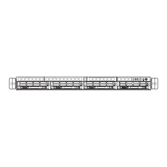
UPER ERVER 6017R-MTLF User's Manual Figure 6-1. Chassis Front View Control Panel SATA Drives (4) Figure 6-2. Chassis Rear View Power Supply I/O Ports Control Panel The control panel (located on the front of the chassis) must be connected to the JF1 connector on the serverboard to provide you with system control buttons and status indicators. -
Page 77: System Fans
Chapter 6: Advanced Chassis Setup System Fans Five 4-cm high-performance fans provide the cooling for the SuperServer 6017R- MTLF. The chassis includes air seals under the fans and at the chassis cross sec- tion, which separates the drive bay area from the serverboard area of the chassis to promote better airfl... -
Page 78: Sata Drive Installation
UPER ERVER 6017R-MTLF User's Manual Accessing the Drive Bays SATA Drives: Because of their hotswap capability, you do not need to access the inside of the chassis or power down the system to install or replace SATA drives. Proceed to the next step for instructions. DVD-ROM Drive (optional): For installing/removing a DVD-ROM drive, you will need to gain access to the inside of the server by removing the top cover of the chassis. -
Page 79: Sata Backplane
Chapter 6: Advanced Chassis Setup Figure 6-4. Mounting a Drive in a Carrier SATA Backplane The SATA drives plug into a backplane that provides power, drive ID and bus termination. Figure 6-5. Removing a Drive from the Server... - Page 80 UPER ERVER 6017R-MTLF User's Manual DVD-ROM Drive Installation (Optional) The top cover of the chassis must be opened to gain full access to the DVD-ROM drive bay. The 6017R-MTLF accomodates only slim DVD-ROM drives. Side mount- ing brackets are needed to mount a slim DVD-ROM drive into the 6017R-MTLF server.
-
Page 81: Power Supply
Chapter 6: Advanced Chassis Setup Power Supply The SuperServer 6017R-MTLF has a single power supply with an output range of 440W-480W. This power supply has the capability of operating with an input voltage of 100-140V or 180-240V. Power must be removed from the server and the server removed from the rack prior to replacing a failed power supply. - Page 82 UPER ERVER 6017R-MTLF User's Manual Notes...
-
Page 83: Chapter 7 Bios
Chapter 7: BIOS Chapter 7 BIOS Introduction This chapter describes the AMI BIOS Setup utility for the X9DRL-7F/X9DRL-EF. It also provides the instructions on how to navigate the AMI BIOS Setup utility screens. The AMI ROM BIOS is stored in a Flash EEPROM and can be easily updated. Starting BIOS Setup Utility To enter the AMI BIOS Setup utility screens, press the <Del>... -
Page 84: Starting The Setup Utility
SUPERSERVER 6017R-MTLF User's Manual Note: For AMI UEFI BIOS Recovery, please refer to the UEFI BIOS Re- covery User Guide posted @http://www.supermicro.com/support/manuals/. Starting the Setup Utility Normally, the only visible Power-On Self-Test (POST) routine is the memory test. As the memory is being tested, press the <Del> key to enter the main menu of the AMI BIOS Setup utility. -
Page 85: Advanced Setup Confi Gurations
Chapter 7: BIOS The AMI BIOS main menu displays the following information: System Time/System Date Use this option to change the system time and date. Highlight System Time or System Date using the arrow keys. Enter new values through the keyboard and press <Enter>. - Page 86 SUPERSERVER 6017R-MTLF User's Manual Boot Feature Quiet Boot Use this feature to select the bootup screen display between POST messages or the OEM logo. Select Disabled to display the POST messages. Select Enabled to display the OEM logo. The default setting is Enabled.
- Page 87 Chapter 7: BIOS to power off when the user presses the power button for 4 seconds or longer. The options are Instant Off and 4 Seconds Override. Restore on AC Power Loss Use this feature to set the power state after a power outage. Select Stay Off for the system power to remain off after a power loss.
- Page 88 SUPERSERVER 6017R-MTLF User's Manual • L2 Cache • L3 Cache CPU Speed This item displays the speed of the CPU installed in a socket specifi ed. 64-bit This item indicates if the CPU installed in the socket specifi ed by the user sup- ports 64-bit technology.
- Page 89 Chapter 7: BIOS Intel® AES-NI Select Enable to use the Intel Advanced Encryption Standard (AES) New In- structions (NI) to ensure data security. The options are Enabled and Disabled. MLC Streamer Prefetcher (Available when supported by the CPU) If set to Enabled, the MLC (mid-level cache) streamer prefetcher will prefetch streams of data and instructions from the main memory to the L2 cache to im- prove CPU performance.
- Page 90 SUPERSERVER 6017R-MTLF User's Manual EIST (Available when Power Technology is set to Custom) EIST (Enhanced Intel SpeedStep Technology) allows the system to automatically adjust processor voltage and core frequency to reduce power consumption and heat dissipation. The options are Disabled (GV3 Disabled), and Enabled (GV3 Enabled).
- Page 91 Chapter 7: BIOS Factory Long Duration Power Limit This item displays the power limit (in watts) set by the manufacturer during which long duration power is maintained. Long Duration Power Limit This item displays the power limit (in watts) set by the user during which long dura- tion power is maintained.
- Page 92 SUPERSERVER 6017R-MTLF User's Manual Ageing Timer Rollover Select Disabled to allow the BIOS to determine how long the system should wait before reallocating resources to PCI-E devices for data transferring when a deadlock occurs. Select 32 us for the BIOS to wait for 32 us second before reallocating system resources for use of PCI-E data transferring when a deadlock occurs.
- Page 93 Chapter 7: BIOS Current QPI Frequency This item displays the current frequency of the QPI Link. Isoc Select Enabled to enable Ischronous support to meet QoS (Quality of Service) requirements. This feature is especially important for virtualization technology. The options are Disabled and Enabled. QPI (Quick Path Interconnect) Link Speed Mode Use this feature to select data transfer speed for QPI Link connections.
- Page 94 SUPERSERVER 6017R-MTLF User's Manual DRAM RAPL Mode RAPL (Running Average Power Limit) provides mechanisms to enforce power consumption limits on supported processors. The options are DRAM RAPL MODE0 , DRAM RAPL MODE1, and Disabled. DDR Speed Use this feature to force a DDR3 memory module to run at a frequency other than what is specifi...
- Page 95 Chapter 7: BIOS Thermal Throttling Throttling improves reliability and reduces power consumption in the proces- sor via automatic voltage control during processor idle states. The options are Disabled and CLTT (Closed Loop Thermal Throttling). South Bridge This feature allows the user to confi gure the settings for the Intel PCH chip. PCH Information This feature displays the following PCH information.
- Page 96 SUPERSERVER 6017R-MTLF User's Manual SATA Confi guration When this submenu is selected, the AMI BIOS automatically detects the presence of IDE or SATA devices and displays the following items. SATA Port0~SATA Port5: The AMI BIOS displays the status of each SATA port as detected by the BIOS.
- Page 97 Chapter 7: BIOS RAID Mode The following items are displayed when RAID Mode is selected: SATA RAID Option ROM/UEFI Driver Select Enabled to boot the system from a SATA RAID device or a UEFI (Unifi ed Extensible Firmware Interface) device. The options are Enabled or Disabled.
- Page 98 SUPERSERVER 6017R-MTLF User's Manual Maximum Read Request Select Auto to allow the system BIOS to automatically set the maximum read request size for a PCI-E device to enhance system performance. The options are Auto, 128 Bytes, 256 Bytes, 512 Bytes, 1024 Bytes, 2048 Bytes, and 4096 Bytes.
- Page 99 Chapter 7: BIOS Network Stack When this featurer is set to Enabled, both PXE (Preboot Execution Environment) and UEFI (Unifi ed Extensible Firmware Interface) will be enabled for network stack support. The options are Enabled and Disabled. Super IO Confi guration Super IO Chip Displays the Super IO chip type.
- Page 100 SUPERSERVER 6017R-MTLF User's Manual SOL (Serial_Over_LAN) Change Settings This option specifi es the base I/O port address and the Interrupt Request address of Serial Port 2. The options are Auto, IO=3F8h; IRQ=4; IO=3F8h; IRQ=3; IO=2F8h; IRQ=3; IO=3E8h; IRQ=5; IO=2E8h; IRQ=7; IO=3F8h; IRQ=3, 4, 5, 6, 7, 10, 11, 12;...
- Page 101 Chapter 7: BIOS Bits Per Second This item sets the transmission speed for a serial port used in Console Redirec- tion. Make sure that the same speed is used in the host computer and the client computer. A lower transmission speed may be required for long and busy lines. The options are 9600, 19200, 38400, 57600, and 115200 (bits per second).
- Page 102 SUPERSERVER 6017R-MTLF User's Manual Legacy OS Redirection Use this feature to select the number of rows and columns used in Console Redirection for legacy OS support. The options are 80x24 and 80x25. Putty Keypad Use this feature to select function key and keypad setting on Putty. The options are VT100, LINUX, XTERMR6, SCO, ESCN, and VT400.
- Page 103 Chapter 7: BIOS Flow Control This feature allows the user to set the fl ow control for Console Redirection to prevent data loss caused by buffer overfl ow. Send a "Stop" signal to stop send- ing data when the receiving buffer is full. Send a "Start" signal to start sending data when the receiving buffer is empty.
- Page 104 SUPERSERVER 6017R-MTLF User's Manual High Precision Event Timer Select Enabled to activate the High Precision Event Timer (HPET) that produces periodic interrupts at a much higher frequency than a Real-time Clock (RTC) does in synchronizing multimedia streams, providing smooth playback, reducing the de- pendency on other timestamp calculation devices, such as an x86 RDTSC Instruc- tion embedded in the CPU.
- Page 105 Chapter 7: BIOS Intel TXT(LT-SX) Confi guration This feature indicates if the following hardware components support the Intel TXT (Trusted Execution Technology), which helps protect against software-based attacks and ensures protection, confi dentiality and integrity of data stored or created on the system.
-
Page 106: Event Logs
SUPERSERVER 6017R-MTLF User's Manual Event Logs Use this menu to confi gure Event Log settings. Change SmBIOS Event Log Settings Enabling/Disabling Options Smbios Event Log Change this item to enable or disable all features of the Smbios Event Logging during boot. -
Page 107: Ipmi
Chapter 7: BIOS This option erases all logged events. The options are No, Yes, Next reset, and Yes, Every reset. When Log is Full This option automatically clears the Event Log memory of all messages when it is full. The options are Do Nothing and Erase Immediately. Log System Boot Event This option toggles the System Boot Event logging to enabled or disabled. - Page 108 SUPERSERVER 6017R-MTLF User's Manual System Event Log Enabling/Disabling Options SEL Components Select Enabled for all system event logging at bootup. The options are Enabled and Disabled. Erasing Settings Erase SEL Select 'Yes, On next reset' to erase all system event logs upon next system reboot.
- Page 109 Chapter 7: BIOS Subnet Mask This item displays the sub-network that this computer belongs to. The value of each three-digit number separated by dots should not exceed 255. Station MAC Address This item displays the Station Mac address for this computer. Mac addresses are 6 two-digit hexadecimal numbers.
-
Page 110: Boot
SUPERSERVER 6017R-MTLF User's Manual Boot This menu allows the user to confi gure the following boot settings for the system. Set Boot Priorities 1st Boot Device/2nd Boot Device/3rd Boot Device/4th Boot Device/5th Boot Device/6th Boot Device Use this feature to specify the sequence of boot priority for a device specifi ed by the user. -
Page 111: Security
Chapter 7: BIOS Network Device BBS Priorities This submenu allows the user to specify the boot priority sequence of a network device. 1st Device UEFI Boot Device BBS Priorities This submenu allows the user to specify the boot priority sequence of a UEFI bootable device. -
Page 112: Save & Exit
SUPERSERVER 6017R-MTLF User's Manual Save & Exit This submenu allows the user to confi gure the Save and Exit settings for the system. Discard Changes and Exit Select this option to quit the BIOS Setup without making any permanent changes to the system confi... - Page 113 Chapter 7: BIOS Discard Changes Select this feature and press <Enter> to discard all the changes and return to the BIOS setup. When the dialog box appears, asking you if you want to load previ- ous values, select Yes to load the values previous saved, or select No to keep the changes you've made so far.
- Page 114 SUPERSERVER 6017R-MTLF User's Manual Notes 7-32...
-
Page 115: Appendix A Bios Post Error Codes
Appendix A: BIOS POST Error Codes Appendix A BIOS Post Error Codes During the POST (Power-On Self-Test) routines, which are performed each time the system is powered on, errors may occur. Non-fatal errors are those which, in most cases, allow the system to continue the boot-up process. - Page 116 SUPERSERVER 6017R-MTLF/6017R-MTLF User's Manual Notes...
-
Page 117: Appendix B System Specifi Cations
Appendix B: System Specifi cations Appendix B System Specifi cations Processors Two Intel® E5-2600 Series processors in LGA2011 sockets Note: refer to our web site for details on supported processors and operating systems. Chipset Intel PCH C602J BIOS ® 128Mb SPI AMI BIOS SM Flash BIOS Memory Capacity Eight memory slots that support up to 256GB of DDR3-1600/1333/1066/800... - Page 118 SUPERSERVER 6017R-MTLF User's Manual System Cooling Five 4-cm high performance fans (FAN-0147L4) One air shroud (Part# MCP-310-19009-0N) System Input Requirements AC Input Voltage: 100-140VAC, 180-240VAC auto-range Rated Input Current: 5.5-4A (100-140V), 3.5-2.5A (180-240V) Rated Input Frequency: 50 to 60 Hz...
- Page 119 Appendix B: System Specifi cations Notes...
- Page 120 SUPERSERVER 6017R-MTLF User's Manual (continued from front) The products sold by Supermicro are not intended for and will not be used in life support systems, medical equipment, nuclear facilities or systems, aircraft, aircraft devices, aircraft/emergency com- munication devices or other critical systems whose failure to perform be reasonably expected to result in signifi...
Need help?
Do you have a question about the SUPERSERVER 6017R-MTLF and is the answer not in the manual?
Questions and answers