Table of Contents
Advertisement
Quick Links
Advertisement
Table of Contents

Related Manuals for Supero SUPERSERVER 6017R-N3RF4+


Summary of Contents for Supero SUPERSERVER 6017R-N3RF4+
- Page 1 UPER ® UPER ERVER 6017R-N3RF4+ 6017R-N3RFT+ USER’S MANUAL 1.0a...
- Page 2 Clara County in the State of California, USA. The State of California, County of Santa Clara shall be the exclusive venue for the resolution of any such disputes. Super Micro's total liability for all claims will not exceed the price paid for the hardware product.
-
Page 3: About This Manual
Preface Preface About This Manual This manual is written for professional system integrators and PC technicians. It provides information for the installation and use of the SuperServer 6017R- N3RF4+/6017R-N3RFT+. Installation and maintenance should be performed by experienced technicians only. Manual Organization Chapter 1: Introduction The fi... - Page 4 UPER ERVER 6017R-N3RF4+/6017R-N3RFT+ User's Manual Chapter 6: Advanced Chassis Setup Refer to Chapter 6 for detailed information on the SC819TQ-R700WB server chas- sis. You should follow the procedures given in this chapter when installing, removing or reconfi guring SAS or peripheral drives and when replacing system power supply modules and cooling fans.
- Page 5 Preface Notes...
-
Page 6: Table Of Contents
UPER ERVER 6017R-N3RF4+/6017R-N3RFT+ User's Manual Table of Contents Chapter 1 Introduction Overview ......................1-1 Serverboard Features ..................1-2 Processors ...................... 1-2 Memory ......................1-2 Onboard SAS ....................1-2 Onboard Serial ATA ..................1-2 Rear I/O Ports ....................1-2 Graphics Controller ..................1-2 Server Chassis Features ................ - Page 7 Table of Contents Chapter 3 System Interface Overview ......................3-1 Control Panel Buttons ..................3-1 UID ........................3-1 Reset ....................... 3-1 Power ......................3-1 Control Panel LEDs ..................3-2 Information LED ....................3-2 NIC2 ........................ 3-2 NIC1 ........................ 3-2 HDD ......................... 3-2 Power ......................
- Page 8 UPER ERVER 6017R-N3RF4+/6017R-N3RFT+ User's Manual Connecting Power Cables ................5-6 Connecting the Control Panel ................. 5-6 I/O Ports ......................5-7 Installing Memory .................... 5-8 Adding PCI Cards ..................5-11 Serverboard Details ..................5-12 X9DRW-3LN4F+/X9DRW-3TF+ Quick Reference ........5-13 Connector Defi nitions ..................5-15 Jumper Settings ....................
-
Page 9: Chapter 1 Introduction
Chapter 1: Introduction Chapter 1 Introduction Overview The SuperServer 6017R-N3RF4+/6017R-N3RFT+ is a high-end server comprised of two main subsystems: the SC819TQ-R700WB 1U server chassis and the X9DRW- 3LN4F+/X9DRW-3TF+ dual processor serverboard. Please refer to our web site for information on operating systems that have been certifi ed for use with the system (www.supermicro.com). -
Page 10: Serverboard Features
UPER ERVER 6017R-N3RF4+/6017R-N3RFT+ User's Manual Serverboard Features At the heart of the SuperServer 6017R-N3RF4+/6017R-N3RFT+ lies the X9DRW- 3LN4F+/X9DRW-3TF+, a dual processor serverboard based on the Intel® C606 chipset. Below are the main features of the serverboard. (See Figure 1-1 for a block diagram of the chipset). -
Page 11: Server Chassis Features
Chapter 1: Introduction Server Chassis Features The 6017R-N3RF4+/6017R-N3RFT+ is built upon the SC819TQ-R700WB chassis. Details on the chassis and on servicing procedures can be found in Chapter 6.The following is a general outline of the main features of the chassis. System Power The SC819TQ-R700WB features a redundant 700W power supply consisting of two power modules. -
Page 12: System Block Diagram
UPER ERVER 6017R-N3RF4+/6017R-N3RFT+ User's Manual Figure 1-1. Intel C606 Chipset: System Block Diagram Note: This is a general block diagram. Please see Chapter 5 for details. Powerville / Twinville L3 / L4 To WIO Riser Card PE3 PE2 CPU REAR LEFT WIO RIGHT WIO U7C1... -
Page 13: Contacting Supermicro
Chapter 1: Introduction Contacting Supermicro Headquarters Address: Super Micro Computer, Inc. 980 Rock Ave. San Jose, CA 95131 U.S.A. Tel: +1 (408) 503-8000 Fax: +1 (408) 503-8008 Email: marketing@supermicro.com (General Information) support@supermicro.com (Technical Support) Web Site: www.supermicro.com Europe Address: Super Micro Computer B.V. - Page 14 UPER ERVER 6017R-N3RF4+/6017R-N3RFT+ User's Manual Notes...
-
Page 15: Chapter 2 Server Installation
Chapter 2: Server Installation Chapter 2 Server Installation Overview This chapter provides a quick setup checklist to get your 6017R-N3RF4+/6017R- N3RFT+ up and running. Following these steps in the order given should enable you to have the system operational within a minimum amount of time. This quick setup assumes that your system has come to you with the processors and memory pre-installed. -
Page 16: Warnings And Precautions
UPER ERVER 6017R-N3RF4+/6017R-N3RFT+ User's Manual installation only in a Restricted Access Location (dedicated equipment rooms, service closets and the like). • This product is not suitable for use with visual display work place devices acccording to §2 of the the German Ordinance for Work with Visual Display Units. Warnings and Precautions! Rack Precautions •... -
Page 17: Rack Mounting Considerations
Chapter 2: Server Installation Rack Mounting Considerations Ambient Operating Temperature If installed in a closed or multi-unit rack assembly, the ambient operating tempera- ture of the rack environment may be greater than the ambient temperature of the room. Therefore, consideration should be given to installing the equipment in an environment compatible with the manufacturer’s maximum rated ambient tempera- ture (Tmra). -
Page 18: Installing The System Into A Rack
UPER ERVER 6017R-N3RF4+/6017R-N3RFT+ User's Manual Installing the System into a Rack This section provides information on installing the 6017R-N3RF4+/6017R-N3RFT+ into a rack unit with the rack rails provided. If the system has already been mounted into a rack, you can skip ahead to Sections 2-5 and 2-6. There are a variety of rack units on the market, which may mean the assembly procedure will differ slightly. -
Page 19: Installing The Outer Rails
Chapter 2: Server Installation Installing the Outer Rails Installing the Outer Rails to the Rack 1. Measure the distance from the front rail to the rear rail of the rack. 2. Attach a short bracket to the front side of the right outer rail and a long bracket to the rear side of the right outer rail. -
Page 20: Installing The Server Into A Telco Rack
UPER ERVER 6017R-N3RF4+/6017R-N3RFT+ User's Manual Installing the Server into the Rack Installing the Chassis into a Rack (Figure 2-3) 1. Confi rm that chassis includes the inner rails and rail extensions . Also, confi rm that the outer rails are installed on the rack. 2. - Page 21 Chapter 2: Server Installation Figure 2-3. Installing the Server into a Rack Warning! To prevent bodily injury when mounting or servicing this unit in a rack, you must take special precautions to ensure that the system remains stable. The following guidelines are provided to ensure your safety: •...
- Page 22 UPER ERVER 6017R-N3RF4+/6017R-N3RFT+ User's Manual Notes...
-
Page 23: Chapter 3 System Interface
Chapter 3: System Interface Chapter 3 System Interface Overview There are several LEDs on the control panel as well as others on the hard drive carriers to keep you constantly informed of the overall status of the system as well as the activity and health of specifi... -
Page 24: Control Panel Leds
UPER ERVER 6017R-N3RF4+/6017R-N3RFT+ User's Manual Control Panel LEDs The control panel located on the front of the SC819TQ chassis has fi ve LEDs. These LEDs provide you with critical information related to different parts of the system. This section explains what each LED indicates when illuminated and any corrective action you may need to take. -
Page 25: Power
Chapter 3: System Interface Power Indicates power is being supplied to the system's power supply units. This LED should normally be illuminated when the system is operating. Drive Carrier LEDs Green: Each drive carrier has a green LED. When illuminated, this green LED indicates drive activity. - Page 26 UPER ERVER 6017R-N3RF4+/6017R-N3RFT+ User's Manual Notes...
-
Page 27: Chapter 4 Standardized Warning Statements For Ac Systems
Chapter 4: Warning Statements for AC Systems Chapter 4 Standardized Warning Statements for AC Systems About Standardized Warning Statements The following statements are industry standard warnings, provided to warn the user of situations which have the potential for bodily injury. Should you have questions or experience difficulty, contact Supermicro's Technical Support department for assistance. - Page 28 UPER ERVER 6017R-N3RF4+/6017R-N3RFT+ User's Manual Warnung WICHTIGE SICHERHEITSHINWEISE Dieses Warnsymbol bedeutet Gefahr. Sie befi nden sich in einer Situation, die zu Verletzungen führen kann. Machen Sie sich vor der Arbeit mit Geräten mit den Gefahren elektrischer Schaltungen und den üblichen Verfahren zur Vorbeugung vor Unfällen vertraut.
- Page 29 Warning Statements for AC Systems ﺟﺴﺪﻳﺔ ﺍﺻﺎﺑﺔ ﺗﺘﺴﺒﺐ ﻓﻲ ﺣﺎﻟﺔ ﻳﻤﻜﻦ ﺃﻥ ﺍﻧﻚ ﻓﻲ ﺧﻄﺮ ﻳﻌﻨﻲ ﻫﺬﺍ ﺍﻟﺮﻣﺰ !ﺗﺤﺬﻳﺮ ﺍﻟﺪﻭﺍﺋﺮ ﺑﺎﻟﻤﺨﺎﻁﺮ ﺍﻟﻨﺎﺟﻤﺔ ﻋﻦ ﻦ ﻋﻠﻰ ﻋﻠﻢ ، ﻛ ﻣﻌﺪﺍﺕ ﺗﻌﻤﻞ ﻋﻠﻰ ﺃﻱ ﻗﺒﻞ ﺃﻥ ﺍﻟﻜﻬﺮﺑﺎﺋﻴﺔ ﺣﻮﺍﺩﺙ ﺃﻱ ﻭﻗﻮﻉ ﻤﻨﻊ ﻟ ﺍﻟﻮﻗﺎﺋﻴﺔ...
-
Page 30: Installation Instructions
UPER ERVER 6017R-N3RF4+/6017R-N3RFT+ User's Manual Installation Instructions Warning! Read the installation instructions before connecting the system to the power source. 警告 将此系统连接电源前,请先阅读安装说明。 警告 將系統與電源連接前,請先閱讀安裝說明。 Warnung Vor dem Anschließen des Systems an die Stromquelle die Installationsanweisungen lesen. ¡Advertencia! Lea las instrucciones de instalación antes de conectar el sistema a la red de alimentación. -
Page 31: Circuit Breaker
Chapter 4: Warning Statements for AC Systems Circuit Breaker Warning! This product relies on the building's installation for short-circuit (overcurrent) protection. Ensure that the protective device is rated not greater than: 250 V, 20 A. 警告 此产品的短路(过载电流)保护由建筑物的供电系统提供,确保短路保护设备的额定电 流不大于250V,20A。 警告 此產品的短路(過載電流)保護由建築物的供電系統提供,確保短路保護設備的額定電 流不大於250V,20A。... -
Page 32: Power Disconnection Warning
UPER ERVER 6017R-N3RF4+/6017R-N3RFT+ User's Manual Waarschuwing Dit product is afhankelijk van de kortsluitbeveiliging (overspanning) van uw electrische installatie. Controleer of het beveiligde aparaat niet groter gedimensioneerd is dan 220V, 20A. Power Disconnection Warning Warning! The system must be disconnected from all sources of power and the power cord removed from the power supply module(s) before accessing the chassis interior to install or remove system components. - Page 33 Chapter 4: Warning Statements for AC Systems ¡Advertencia! El sistema debe ser disconnected de todas las fuentes de energía y del cable eléctrico quitado de los módulos de fuente de alimentación antes de tener acceso el interior del chasis para instalar o para quitar componentes de sistema. Attention Le système doit être débranché...
-
Page 34: Equipment Installation
UPER ERVER 6017R-N3RF4+/6017R-N3RFT+ User's Manual Equipment Installation Warning! Only trained and qualifi ed personnel should be allowed to install, replace, or service this equipment. 警告 只有经过培训且具有资格的人员才能进行此设备的安装、更换和维修。 警告 只有經過受訓且具資格人員才可安裝、更換與維修此設備。 Warnung Das Installieren, Ersetzen oder Bedienen dieser Ausrüstung sollte nur geschultem, qualifi ziertem Personal gestattet werden. ¡Advertencia! Solamente el personal califi... -
Page 35: Restricted Area
Chapter 4: Warning Statements for AC Systems Waarschuwing Deze apparatuur mag alleen worden geïnstalleerd, vervangen of hersteld door geschoold en gekwalifi ceerd personeel. Restricted Area Warning! This unit is intended for installation in restricted access areas. A restricted access area can be accessed only through the use of a special tool, lock and key, or other means of security. -
Page 36: Battery Handling
UPER ERVER 6017R-N3RF4+/6017R-N3RFT+ User's Manual אזור עם גישה מוגבלת !אזהרה יש להתקין את היחידה באזורים שיש בהם הגבלת גישה. הגישה ניתנת בעזרת .('כלי אבטחה בלבד )מפתח, מנעול וכד ﻣﺤﻈﻮﺭﺓ ﻣﻨﺎﻁﻖ ﻟﺘﺮﻛﻴﺒﻬﺎ ﻓﻲ ﻫﺬﻩ ﺍﻟﻮﺣﺪﺓ ﺗﺨﺼﻴﺺ ﺗﻢ ،ﺃﺩﺍﺓ ﺧﺎﺻﺔ ﻣﻦ ﺧﻼﻝ ﺍﺳﺘﺨﺪﺍﻡ ﻓﻘﻂ... - Page 37 Chapter 4: Warning Statements for AC Systems Warnung Bei Einsetzen einer falschen Batterie besteht Explosionsgefahr. Ersetzen Sie die Batterie nur durch den gleichen oder vom Hersteller empfohlenen Batterietyp. Entsorgen Sie die benutzten Batterien nach den Anweisungen des Herstellers. Attention Danger d'explosion si la pile n'est pas remplacée correctement. Ne la remplacer que par une pile de type semblable ou équivalent, recommandée par le fabricant.
-
Page 38: Redundant Power Supplies
UPER ERVER 6017R-N3RF4+/6017R-N3RFT+ User's Manual Redundant Power Supplies Warning! This unit might have more than one power supply connection. All connections must be removed to de-energize the unit. 警告 此部件连接的电源可能不止一个,必须将所有电源断开才能停止给该部件供电。 警告 此裝置連接的電源可能不只一個,必須切斷所有電源才能停止對該裝置的供電。 Warnung Dieses Gerät kann mehr als eine Stromzufuhr haben. Um sicherzustellen, dass der Einheit kein trom zugeführt wird, müssen alle Verbindungen entfernt werden. -
Page 39: Backplane Voltage
Chapter 4: Warning Statements for AC Systems ﺍﻣﺪﺍﺩ ﺍﻟﻄﺎﻗﺔ ﺑﻮﺣﺪﺍﺕ ﻋﺪﺓ ﺍﺗﺼﺎﻻﺕ ﺠﻬﺎﺯ ﺍﻟ ﻳﻜﻮﻥ ﻟﻬﺬﺍ ﻗﺪ ﺍﻟﻜﻬﺮﺑﺎء ﻋﻦ ﻮﺣﺪﺓ ﺍﻟ ﻟﻌﺰﻝ ﻛﺎﻓﺔ ﺍﻻﺗﺼﺎﻻﺕ ﻳﺠﺐ ﺇﺯﺍﻟﺔ Waarschuwing Deze eenheid kan meer dan één stroomtoevoeraansluiting bevatten. Alle aansluitingen dienen verwijderd te worden om het apparaat stroomloos te maken. Backplane Voltage Warning! Hazardous voltage or energy is present on the backplane when the system is... -
Page 40: Comply With Local And National Electrical Codes
UPER ERVER 6017R-N3RF4+/6017R-N3RFT+ User's Manual מתח בפנל האחורי !הרה אז קיימת סכנת מתח בפנל האחורי בזמן תפעול המערכת. יש להיזהר במהלך .העבודה ﺍﻟﻠﻮﺣﺔ ﺃﻭﺍﻟﻄﺎﻗﺔ ﺍﻟﻤﻮﺟﻮﺩﺓ ﻋﻠﻰ ﺍﻟﺘﻴﺎﺭ ﺍﻟﻜﻬﺮﺑﺎﺋﻲ ﻣﻦ ﺧﻄﺮ ﻫﻨﺎﻙ ﻫﺬﺍ ﺍﻟﺠﻬﺎﺯ ﺧﺪﻣﺔ ﻛﻦ ﺣﺬﺭﺍ ﻋﻨﺪ ﻳﻌﻤﻞ ﺍﻟﻨﻈﺎﻡ ﻋﻨﺪﻣﺎ ﻳﻜﻮﻥ Waarschuwing Een gevaarlijke spanning of energie is aanwezig op de backplane wanneer het systeem in gebruik is. -
Page 41: Product Disposal
Chapter 4: Warning Statements for AC Systems Attention L'équipement doit être installé conformément aux normes électriques nationales et locales. תיאום חוקי החשמל הארצי !אזהרה הציוד חייבת להיות תואמת לחוקי החשמל המקומיים והארציים התקנת ﺍﻟﻤﺘﻌﻠﻘﺔ ﺍﻟﻤﺤﻠﻴﺔ ﻭﺍﻟﻮﻁﻨﻴﺔ ﻘﻮﺍﻧﻴﻦ ﻳﺠﺐ ﺃﻥ ﻳﻤﺘﺜﻞ ﻟﻠ ﺍﻟﻜﻬﺮﺑﺎﺋﻴﺔ... -
Page 42: Hot Swap Fan Warning
UPER ERVER 6017R-N3RF4+/6017R-N3RFT+ User's Manual ¡Advertencia! Al deshacerse por completo de este producto debe seguir todas las leyes y reglamentos nacionales. Attention La mise au rebut ou le recyclage de ce produit sont généralement soumis à des lois et/ou directives de respect de l'environnement. Renseignez-vous auprès de l'organisme compétent. - Page 43 Chapter 4: Warning Statements for AC Systems 警告 當您從機架移除風扇裝置,風扇可能仍在轉動。小心不要將手指、螺絲起子和其他 物品太靠近風扇。 Warnung Die Lüfter drehen sich u. U. noch, wenn die Lüfterbaugruppe aus dem Chassis genommen wird. Halten Sie Finger, Schraubendreher und andere Gegenstände von den Öffnungen des Lüftergehäuses entfernt. ¡Advertencia! Los ventiladores podran dar vuelta cuando usted quite ell montaje del ventilador del chasis.
-
Page 44: Power Cable And Ac Adapter
UPER ERVER 6017R-N3RF4+/6017R-N3RFT+ User's Manual Power Cable and AC Adapter Warning! When installing the product, use the provided or designated connection cables, power cables and AC adaptors. Using any other cables and adaptors could cause a malfunction or a fi re. Electrical Appliance and Material Safety Law prohibits the use of UL or CSA -certifi... - Page 45 Chapter 4: Warning Statements for AC Systems Attention Lors de l'installation du produit, utilisez les bables de connection fournis ou désigné. L'utilisation d'autres cables et adaptateurs peut provoquer un dysfonctionnement ou un incendie. Appareils électroménagers et de loi sur la sécurité Matériel interdit l'utilisation de UL ou CSA câbles certifi...
- Page 46 UPER ERVER 6017R-N3RF4+/6017R-N3RFT+ User's Manual Notes 4-20...
-
Page 47: Chapter 5 Advanced Serverboard Setup
Chapter 5: Advanced Serverboard Setup Chapter 5 Advanced Serverboard Setup This chapter covers the steps required to install processors and heatsinks to the X9DRW-3LN4F+/X9DRW-3TF+ serverboard, connect the data and power cables and install add-on cards. All serverboard jumpers and connections are described and a layout and quick reference chart are included in this chapter. -
Page 48: Installing The Processor And Heatsink
UPER ERVER 6017R-N3RF4+/6017R-N3RFT+ User's Manual Installing the Processor and Heatsink Warning: When handling the processor package, avoid placing direct pressure on the label area of the fan. Notes: • Always connect the power cord last and always remove it before adding, re- moving or changing any hardware components. - Page 49 Chapter 5: Advanced Serverboard Setup 3. With the lever labeled 'Close 1st' fully retracted, gently push down on the 'Open 1st' lever to open the load plate. Lift the load plate to open it completely. Gently push 4. Using your thumb and the index down to pop the load plate fi...
- Page 50 UPER ERVER 6017R-N3RF4+/6017R-N3RFT+ User's Manual Warning: You can only install the CPU to the socket in one direction. Make sure that the CPU is properly inserted into the socket before closing the load plate. If it doesn't close properly, do not force it as it may damage your CPU. Instead, open the load plate again and double-check that the CPU is aligned properly.
-
Page 51: Installing A Cpu Heatsink
Chapter 5: Advanced Serverboard Setup Installing a CPU Heatsink 1. Place the heatsink on top of the CPU so that the four mounting holes are aligned with those on the retention mechanism. 2. Screw in two diagonal screws (i.e. the #1 and the #2 screws) until just snug (do not over-tighten the screws, which may damage the CPU.) 3. -
Page 52: Connecting Cables
UPER ERVER 6017R-N3RF4+/6017R-N3RFT+ User's Manual Connecting Cables Now that the processors are installed, the next step is to connect the cables to the serverboard. Connecting Data Cables The cables used to transfer data from the peripheral devices have been carefully routed in preconfi... -
Page 53: I/O Ports
Chapter 5: Advanced Serverboard Setup Figure 5-1. Front Control Panel Header Pins (JF1) Ground x (key) x (key) Power LED 3.3V HDD LED UID Switch/Vcc NIC1 Link LED NIC1 Active LED NIC2 Link LED NIC2 Active LED Blue: OH/Fan Fail/Power Fail/UID LED Red: (Blue LED Cathode) Power Fail LED 3.3V... -
Page 54: Installing Memory
UPER ERVER 6017R-N3RF4+/6017R-N3RFT+ User's Manual Installing Memory Note: Check the Supermicro web site for recommended memory modules. CAUTION Exercise extreme care when installing or removing DIMM modules to prevent any possible damage. Installing DIMMs 1. Insert the desired number of DIMMs into the memory slots, starting with slot P1-DIMMA1. - Page 55 Chapter 5: Advanced Serverboard Setup Processor & Memory Module Population Confi guration For memory to work properly, follow the tables below for memory installation. Processors and their Corresponding Memory Modules CPU# Corresponding DIMM Modules CPU 1 CPU2 Processor and Memory Module Population Number of CPU and Memory Population Confi...
- Page 56 UPER ERVER 6017R-N3RF4+/6017R-N3RFT+ User's Manual UDIMM Support DIMMs Populated per UDIMM Type POR Speeds (in Ranks per DIMM DDR Channel (Unb. DIMM) MHz) (Any Combination) ECC/Non-ECC DDR3 1066, 1333 SR, DR ECC/Non-ECC DDR3 1066, 1333 SR, DR RDIMM Support DIMMs Populated per RDIMM Type POR Speeds (in Ranks per DIMM...
-
Page 57: Adding Pci Cards
Chapter 5: Advanced Serverboard Setup Adding PCI Cards PCI Expansion Slots Riser cards installed to the system allow you to add PCI expansion cards (see be- low). The SC819TQ-R700WB can support the use of two standard size (full-height, half-length) expansion cards and one low-profi le (4.1" length) expansion card (with pre-installed riser cards). -
Page 58: Serverboard Details
UPER ERVER 6017R-N3RF4+/6017R-N3RFT+ User's Manual Serverboard Details Figure 5-4. SUPER X9DRW-3TF+/X9DRW-3TF+ Layout LAN4 LAN3 LAN1 VGA1 LAN2 COM1 JUIDB1 KB/MOUSE USB0/1 Buzzer IPMI_LAN CTRL 1 SXB1B CTRL 2 X9DRW-3LN4F+ Rev. 1.21 LEM1 CPU2 CTRL BATTERY CPLD JBAT1 JBT1 Clock Intel... -
Page 59: X9Drw-3Ln4F+/X9Drw-3Tf+ Quick Reference
Chapter 5: Advanced Serverboard Setup X9DRW-3LN4F+/X9DRW-3TF+ Quick Reference Jumper Description Default Setting JBT1 Clear CMOS See Section 5-9 C1/JI SMB to PCI-E Slots Pins 2-3 (Normal) JPB1 BMC Enable/Disable Pins 1-2 (Enabled) JPG1 VGA Enable/Disable Pins 1-2 (Enabled) JPL1 LAN1/LAN2 Enable/Disable Pins 1-2 (Enabled) JPL2 LAN3/LAN4 Enable/Disable... - Page 60 UPER ERVER 6017R-N3RF4+/6017R-N3RFT+ User's Manual Onboard Buzzer (Internal Speaker) SXB1A/1B/1C SMC-Proprietary WIO_L (Left) Add-On Card Slot SXB2 SMC-Proprietary WIO_R (Right) Add-On Card Slot T-SGPIO 1/2 Serial-Link General_Purpose IO Headers (J17/J18) USB 0/1 Rear I/O USB 0/1 Ports USB 2/3, 4/5 Front Accessible USB 2/3, 4/5 Headers USB 6 Front Panel Type A USB 6 Port...
-
Page 61: Connector Defi Nitions
Chapter 5: Advanced Serverboard Setup Connector Defi nitions ATX Power 24-pin Connector Pin Defi nitions Pin# Defi nition Pin # Defi nition ATX Power Connector +3.3V +3.3V The primary ATX power supply con- -12V +3.3V nector meets the SSI EPS 12V speci- fi... - Page 62 UPER ERVER 6017R-N3RF4+/6017R-N3RFT+ User's Manual NMI Button NMI Button Pin Defi nitions (JF1) The non-maskable interrupt button Pin# Defi nition header is located on pins 19 and 20 Control of JF1. Refer to the table on the right Ground for pin defi nitions. Power LED Power LED Pin Defi...
- Page 63 Chapter 5: Advanced Serverboard Setup Overheat (OH)/Fan Fail/PWR Fail/ OH/Fan Fail/ PWR Fail/Blue_UID UID LED LED Pin Defi nitions (JF1) Pin# Defi nition Connect an LED to pins 7 and 8 of Blue_LED Cathode (UID) JF1 to provide advanced warning of OH/Fan Fail/PWR Fail/UID LED chassis overheating or fan failure.
- Page 64 UPER ERVER 6017R-N3RF4+/6017R-N3RFT+ User's Manual Fan Headers The serverboard has six system/ Fan Header Pin Defi nitions CPU fan headers (Fan 1~Fan 5, Fan Pin# Defi nition A). All are 4-pin fans headers, which Ground are backward compatible with tradi- +12V tional 3-pin fans.
- Page 65 Chapter 5: Advanced Serverboard Setup TPM Header/Port 80 TPM/Port 80 Header Pin Defi nitions A Trusted Platform Module/Port 80 Pin # Defi nition Pin # Defi nition header is located at JTPM1 to provide LCLK TPM support and Port 80 connection. LFRAME# <(KEY)>...
- Page 66 UPER ERVER 6017R-N3RF4+/6017R-N3RFT+ User's Manual T-SGPIO 1/2 Headers T-SGPIO Two SGPIO (Serial-Link General Pin Defi nitions Purpose Input/Output) headers are Pin# Defi nition Defi nition located at J17 and J18. These head- ers support Serial Link interface for Ground Data onboard SATA connections.
- Page 67 Chapter 5: Advanced Serverboard Setup Unit Identifi er Switch The UID switch is located next to the 10G LAN 4 port on the backplane. The rear UID LED (LE2) is located next to the UID switch. The Front Panel UID LED is located on pins UID Switch 7/8 of JF1.
- Page 68 UPER ERVER 6017R-N3RF4+/6017R-N3RFT+ User's Manual Serial Ports Serial COM) Ports Pin Defi nitions Two COM connections (COM1 & Pin # Defi nition Pin # Defi nition COM2) are located on the serverboard. COM1 is located on the Backplane I/O panel. COM2, located close to USB 4/5 Connectors, is used to provide front access support.
-
Page 69: Jumper Settings
Chapter 5: Advanced Serverboard Setup Jumper Settings Explanation of Jumpers To modify the operation of the serverboard, jumpers can be used Connector to choose between optional settings. Pins Jumpers create shorts between two pins to change the function of the Jumper connector. - Page 70 UPER ERVER 6017R-N3RF4+/6017R-N3RFT+ User's Manual JPL1/JPL2 LAN Port Use JPL1 to enable/disable LAN ports Jumper Settings 1/2, and use JPL2 for LAN ports Jumper Setting Defi nition 3/4. See the table on the right for Pins 1-2 Enabled jumper settings. The default setting Pins 2-3 Disabled is Enabled.
-
Page 71: 5-10 Onboard Indicators
Chapter 5: Advanced Serverboard Setup 5-10 Onboard Indicators Activity LED Link LED LAN LEDs The Ethernet ports (located beside the VGA port) have two LEDs. On each LAN LED Gigabit LAN port, one LED indicates Connection Speed Indicator activity when blinking while the other LED Color Defi... -
Page 72: 5-11 Sas/Sata Port Connections
UPER ERVER 6017R-N3RF4+/6017R-N3RFT+ User's Manual 5-11 SAS/SATA Port Connections SATA Port Pin Defi nitions Pin # Defi nition SATA Ports Ground There are six Serial ATA Ports (I- SATA0 ~I - SATA 5) located on the serverboard, including four SATA2 Ground ports and two SATA3 ports. -
Page 73: 5-12 Installing Software
Chapter 5: Advanced Serverboard Setup 5-12 Installing Software After the hardware has been installed, you should fi rst install the operating system and then the drivers. The necessary drivers are all included on the Supermicro CDs that came packaged with your serverboard. Figure 5-5. -
Page 74: Superdoctor Iii
UPER ERVER 6017R-N3RF4+/6017R-N3RFT+ User's Manual SuperDoctor III The SuperDoctor III program is a Web base management tool that supports remote management capability. It includes Remote and Local Management tools. The local management is called SD III Client. The SuperDoctor III program allows you to moni- tor the environment and operations of your system. - Page 75 Chapter 5: Advanced Serverboard Setup Figure 5-7. SuperDoctor III Interface Display Screen (Remote Control) Note: SD III Software Revision 1.0 can be downloaded from our Web Site at: ftp:// ftp.supermicro.com/utility/Supero_Doctor_III/. You can also download SDIII User's Guide at: http://www.supermicro.com/manuals/other/SDIII_User_Guide.pdf. For Linux, we will still recommend Supero Doctor II.
-
Page 76: 5-13 Onboard Battery
UPER ERVER 6017R-N3RF4+/6017R-N3RFT+ User's Manual 5-13 Onboard Battery Please handle used batteries carefully. Do not damage the battery in any way; a damaged battery may release hazardous materials into the environment. Do not discard a used battery in the garbage or a public landfi ll. Please comply with the regulations set up by your local hazardous waste management agency to dispose of your used battery properly. -
Page 77: Chapter 6 Advanced Chassis Setup
Chapter 6: Advanced Chassis Setup Chapter 6 Advanced Chassis Setup This chapter covers the steps required to install components and perform mainte- nance on the SC819TQ chassis. For component installation, follow the steps in the order given to eliminate the most common problems encountered. If some steps are unnecessary, skip ahead to the next step. -
Page 78: Control Panel
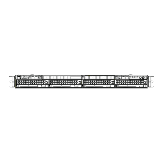
UPER ERVER 6017R-N3RF4+/6017R-N3RFT+ User's Manual Figure 6-1. Chassis: Front and Rear Views Slim DVD-ROM (optional) Control Panel Hard Drive Bays (4) Power Supplies IPMI LAN USB Ports PCI Expansion Slots (w/riser cards) Mouse/Keyboard Ports COM1 Port VGA Port Ethernet (LAN) Ports* Control Panel The control panel (located on the front of the chassis) must be connected to the JF1 connector on the serverboard to provide you with system status indications. -
Page 79: System Fans
Chapter 6: Advanced Chassis Setup System Fans Five 4-cm heavy duty counter-rotating fans provide the cooling for the 6017R- N3RF4+/6017R-N3RFT+. Each fan unit is actually made up of two fans joined back- to-back, which rotate in opposite directions. This counter-rotating action generates exceptional airfl... -
Page 80: Accessing The Drive Bays
UPER ERVER 6017R-N3RF4+/6017R-N3RFT+ User's Manual Figure 6-2. System Cooling Fans Accessing the Drive Bays Hard Drives: Because of their hotswap capability, you do not need to access the inside of the chassis or power down the system to install or replace the SAS/SATA drives. -
Page 81: Hard Drive Installation
Chapter 6: Advanced Chassis Setup Hard Drive Installation The hard drives are mounted in drive carriers to simplify their installation and removal from the chassis. System power may remain on when removing carriers with drives installed. These carriers also help promote proper airfl ow for the drive bays. -
Page 82: Hard Drive Backplane
UPER ERVER 6017R-N3RF4+/6017R-N3RFT+ User's Manual Installing/Removing a Hard Drive 1. To remove a carrier, push the release button located beside the drive LEDs. 2. Swing the colored handle fully out and use it to pull the unit straight out (see Figure 6-4). -
Page 83: Dvd-Rom Drive Installation
Chapter 6: Advanced Chassis Setup DVD-ROM Drive Installation The top cover of the chassis must be opened to gain full access to the DVD-ROM drive bay. The 6017R-N3RF4+/6017R-N3RFT+ accomodates only slim DVD-ROM drives. Side mounting brackets are needed to mount a slim DVD-ROM drive in the server. -
Page 84: Power Supply
UPER ERVER 6017R-N3RF4+/6017R-N3RFT+ User's Manual Power Supply The SuperServer 6017R-N3RF4+/6017R-N3RFT+ has a 700 watt redundant power supply consisting of two power modules. Each power supply module has an auto- switching capability, which enables it to automatically sense and operate at a 100V - 240V input voltage. - Page 85 Chapter 6: Advanced Chassis Setup Figure 6-5. Removing/Replacing the Power Supply...
- Page 86 UPER ERVER 6017R-N3RF4+/6017R-N3RFT+ User's Manual Notes 6-10...
-
Page 87: Chapter 7 Bios
Chapter 7: BIOS Chapter 7 BIOS Introduction This chapter describes the AMI BIOS Setup utility for the X9DRW-3LN4F+/X9DRW- 3LN4T+. It also provides the instructions on how to navigate the AMI BIOS Setup utility screens. The AMI ROM BIOS is stored in a Flash EEPROM and can be easily updated. -
Page 88: Main Setup
UPER ERVER 6017R-N3RF4+/6017R-N3RFT+ User's Manual How To Change the Confi guration Data The confi guration data that determines the system parameters may be changed by entering the AMI BIOS Setup utility. This Setup utility can be accessed by pressing <F2> at the appropriate time during system boot. Note: For AMI UEFI BIOS Recovery, please refer to the UEFI BIOS Re- covery User Guide posted @http://www.supermicro.com/support/manuals/. -
Page 89: Advanced Setup Confi Gurations
Chapter 7: BIOS System Date This item displays the system date in Day MM/DD/YY format (e.g. Wed 10/12/2011). System Time This item displays the system time in HH:MM:SS format (e.g. 15:32:52). Supermicro X9DRW-3LN4F+/X9DRW-3TF+ Version This item displays the SMC version of the BIOS ROM used in this system. Build Date This item displays the date that the BIOS Setup utility was built. -
Page 90: Boot Features
UPER ERVER 6017R-N3RF4+/6017R-N3RFT+ User's Manual Boot Features Quiet Boot This feature allows the user to select bootup screen display between POST mes- sages and the OEM logo. Select Disabled to display the POST messages. Select Enabled to display the OEM logo instead of the normal POST messages. The op- tions are Enabled and Disabled. - Page 91 Chapter 7: BIOS Restore on AC Power Loss Use this feature to set the power state after a power outage. Select Stay Off for the system power to remain off after a power loss. Select Power On for the system power to be turned on after a power loss.
- Page 92 UPER ERVER 6017R-N3RF4+/6017R-N3RFT+ User's Manual CPU Speed This item displays the speed of the CPU installed in Socket 1/Socket 2. 64-bit This item indicates if the CPU installed in Socket 1 or Socket 2 supports 64-bit technology. Clock Spread Spectrum Select Enable to enable Clock Spectrum support, which will allow the BIOS to moni- tor and attempt to reduce the level of Electromagnetic Interference caused by the components whenever needed.
- Page 93 Chapter 7: BIOS MLC Streamer Prefetcher (Available when supported by the CPU) If set to Enabled, the MLC (mid-level cache) streamer prefetcher will prefetch streams of data and instructions from the main memory to the L2 cache to improve CPU performance. The options are Disabled and Enabled. MLC Spatial Prefetch (Available when supported by the CPU) If this feature is set to Disabled, The CPU prefetches the cache line for 64 bytes.
- Page 94 UPER ERVER 6017R-N3RF4+/6017R-N3RFT+ User's Manual EIST (Available when Power Technology is set to Custom) EIST (Enhanced Intel SpeedStep Technology) allows the system to au- tomatically adjust processor voltage and core frequency to reduce power consumption and heat dissipation. The options are Disabled (GV3 Disabled), and Enabled (GV3 Enabled).
-
Page 95: North Bridge
Chapter 7: BIOS Factory Long Duration Power Limit This item displays the power limit set by the manufacturer during which long duration power is maintained. Long Duration Power Limit This item displays the power limit set by the user during which long duration power is maintained. - Page 96 UPER ERVER 6017R-N3RF4+/6017R-N3RFT+ User's Manual Data Direct I/O Select Enabled to enable Intel I/OAT (I/O Acceleration Technology), which sig- nifi cantly reduces CPU overhead by leveraging CPU architectural improvements and freeing the system resource for other tasks. The options are Disabled and Enabled.
- Page 97 Chapter 7: BIOS Current QPI Frequency This item displays the frequency of the QPI Link. Isoc Select Enabled to enable Ischronous support to meet QoS (Quality of Service) requirements. This feature is especially important for virtualization technology. The options are Enabled and Disabled. QPI (Quick Path Interconnect) Link Speed Mode Use this feature to select data transfer speed for QPI Link connections.
- Page 98 UPER ERVER 6017R-N3RF4+/6017R-N3RFT+ User's Manual Memory Mode When Independent is selected, all DIMMs are available to the operating system. When Mirroring is selected, the motherboard maintains two identical copies of all data in memory for data backup. When Lockstep is selected, the motherboard uses two areas of memory to run the same set of operations in parallel.
- Page 99 Chapter 7: BIOS Data Scrambling Select Enabled to enable data scrambling to ensure data security and integrity. The options are Disabled and Enabled. Device Tagging Select Enabled to support device tagging. The options are Disabled and En- abled. Thermal Throttling Throttling improves reliability and reduces power consumption in the proces- sor via automatic voltage control during processor idle states.
- Page 100 UPER ERVER 6017R-N3RF4+/6017R-N3RFT+ User's Manual for EFI (Extensive Firmware Interface) applications only. The settings are Disabled, Enabled and Auto. Port 60/64 Emulation Select Enabled to enable I/O port 60h/64h emulation support for the legacy USB keyboard so that it can be fully supported by the operating systems that does not recognize a USB device.
- Page 101 Chapter 7: BIOS AHCI Mode The following items are displayed when the AHCI Mode is selected. Aggressive Link Power Management Select Enabled to enable Aggressive Link Power Management support for Cougar Point B0 stepping and beyond. The options are Enabled and Disabled.
- Page 102 UPER ERVER 6017R-N3RF4+/6017R-N3RFT+ User's Manual PCIe/PCI/PnP Confi guration PCI ROM Priority Use this feature to select the Option ROM to boot the system when there are mul- tiple Option ROMs available in the system. The options are EFI Compatible ROM and Legacy ROM.
- Page 103 Extensible Firmware Interface) for network stack support. The options are Enabled and Disabled. Super IO Confi guration Super IO Chip: This item displays the Super IO chip used in the motherboard. Serial Port 1 Confi guration Serial Port Select Enabled to enable a serial port specifi ed by the user. The options are En- abled and Disabled.
-
Page 104: Serial Port Console Redirection
UPER ERVER 6017R-N3RF4+/6017R-N3RFT+ User's Manual Device Mode Use this feature to select the desired mode for a serial port specifi ed. The options are Normal and High Speed. Serial Port 2 Confi guration Serial Port Select Enabled to enable a serial port specifi ed by the user. The options are En- abled and Disabled. -
Page 105: Console Redirection Settings
Chapter 7: BIOS Console Redirection Settings This feature allows the user to specify how the host computer will exchange data with the client computer, which is the remote computer used by the user. Terminal Type This feature allows the user to select the target terminal emulation type for Con- sole Redirection. - Page 106 UPER ERVER 6017R-N3RF4+/6017R-N3RFT+ User's Manual VT-UTF8 Combo Key Support Select Enabled to enable VT-UTF8 Combination Key support for ANSI/VT100 terminals. The options are Enabled and Disabled. Recorder Mode Select Enabled to capture the data displayed on a terminal and send it as text messages to a remote server.
-
Page 107: Acpi Settings
Chapter 7: BIOS Terminal Type This feature allows the user to select the target terminal emulation type for Con- sole Redirection. Select VT100 to use the ASCII character set. Select VT100+ to add color and function key support. Select ANSI to use the extended ASCII character set. - Page 108 UPER ERVER 6017R-N3RF4+/6017R-N3RFT+ User's Manual tion embedded in the CPU. The High Performance Event Timer is used to replace the 8254 Programmable Interval Timer. The options are Enabled and Disabled. Trusted Computing (Available when a TPM device is detected by the BIOS) Confi...
- Page 109 Chapter 7: BIOS Intel TXT (LT-SX) Confi guration This feature displays the following TXT confi guration setting. TXT (LT-SX) Support: This item indicated if the Intel TXT support is enabled or disabled. Intel TXT (LT-SX) Dependencies This feature displays the features that need to be enabled for the Intel Trusted Execution Technology to work properly in the system.
-
Page 110: Event Logs
UPER ERVER 6017R-N3RF4+/6017R-N3RFT+ User's Manual Blink LEDs This feature allows the user to specify the duration for LEDs to blink. The range is from 0 ~ 15 seconds. PORT CONFIGURATION INFORMATION This section displays the following port information: • UEFI Driver •... -
Page 111: Change Smbios Event Log Settings
Chapter 7: BIOS Change SMBIOS Event Log Settings This feature allows the user to confi gure SMBIOS Event settings. Enabling/Disabling Options SMBIOS Event Log Select Enabled to enable SMBIOS (System Management BIOS) Event Logging during system boot. The options are Enabled and Disabled. Runtime Error Logging Support Select Enabled to support Runtime Error Logging. -
Page 112: Ipmi
UPER ERVER 6017R-N3RF4+/6017R-N3RFT+ User's Manual METW (Multiple Event Count Time Window) This item allows the user to decide how long (in minutes) should the multiple event counter wait before generating a new event log. Enter a number between 0 to 99. The default setting is 60. -
Page 113: System Event Log
Chapter 7: BIOS IPMI Firmware Revision This item indicates the IPMI fi rmware revision used in your system. IPMI Status This item indicates the status of the IPMI fi rmware installed in your system. System Event Log Enabling/Disabling Options SEL Components Select Enabled for all system event logging at bootup. -
Page 114: Boot
UPER ERVER 6017R-N3RF4+/6017R-N3RFT+ User's Manual Update IPMI LAN Confi guration This feature allows the user to decide if the BIOS should confi gure the IPMI setting at next system boot. The options are No and Yes. If the option is set to Yes, the user is allow to confi... -
Page 115: Security
Chapter 7: BIOS USB Device BBS Priorities, Network Device BBS Priorities, Hard Disk Drives Use these options to set the order of the legacy network and USB devices detected by the motherboard. Add New Boot Option This feature allows the user to add a new EFI boot option to the boot order. ... -
Page 116: Save & Exit
UPER ERVER 6017R-N3RF4+/6017R-N3RFT+ User's Manual Save & Exit This submenu allows the user to confi gure the Save and Exit settings for the system. Discard Changes and Exit Select this option to quit the BIOS Setup without making any permanent changes to the system confi... - Page 117 Chapter 7: BIOS the dialog box appears, asking you if you want to exit the BIOS setup without sav- ing, click Yes to quit BIOS without saving the changes, or click No to quit the BIOS and save changes. Save Options Save Changes Select this option and press <Enter>...
- Page 118 UPER ERVER 6017R-N3RF4+/6017R-N3RFT+ User's Manual Select this feature and press <Enter> to save the current settings as the user's defaults. When the dialog box appears, asking you if you want to save values as user's defaults, click Yes to save the current values as user's default settings, or click No to keep the defaults previously saved as the user's defaults.
-
Page 119: Appendix A Bios Error Beep Codes
Appendix A: BIOS Error Beep Codes Appendix A BIOS Error Beep Codes During the POST (Power-On Self-Test) routines, which are performed each time the system is powered on, errors may occur. Non-fatal errors are those which, in most cases, allow the system to continue the boot-up process. - Page 120 UPER ERVER 6017R-N3RF4+/6017R-N3RFT+ User's Manual Notes...
-
Page 121: Appendix B System Specifi Cations
Appendix B: System Specifi cations Appendix B System Specifi cations Processors Single or dual Intel® E5-2600 Series processors in LGA2011 sockets Note: Please refer to our web site for a complete listing of supported processors. Chipset Intel C606 chipset BIOS 16 Mb AMI®... - Page 122 UPER ERVER 6017R-N3RF4+/6017R-N3RFT+ User's Manual Serverboard 6017R-N3RF4+: X9DRW-3LN4F+ (Proprietary form factor) 6017R-N3RFT+: X9DRW-3TF+ (Proprietary form factor) Dimensions: 16.5 x 12.8 in (419 x 325 mm) Chassis SC819TQ-R700WB (1U rackmount) Dimensions: (WxHxD) 19 x 1.7 x 27.75 in. (483 x 43 x 705 mm) Weight Gross Weight: 38.5 lbs.
- Page 123 Appendix B: System Specifi cations Regulatory Compliance Electromagnetic Emissions: FCC Class A, EN 55022 Class A, EN 61000-3-2/-3-3, CISPR 22 Class A Electromagnetic Immunity: EN 55024/CISPR 24, (EN 61000-4-2, EN 61000-4-3, EN 61000-4-4, EN 61000-4-5, EN 61000-4-6, EN 61000-4-8, EN 61000-4-11) Safety: CSA/EN/IEC/UL 60950-1 Compliant, UL or CSA Listed (USA and Canada), CE Marking (Europe) California Best Management Practices Regulations for Perchlorate Materials:...
- Page 124 UPER ERVER 6017R-N3RF4+/6017R-N3RFT+ User's Manual (continued from front) The products sold by Supermicro are not intended for and will not be used in life support systems, medical equipment, nuclear facilities or systems, aircraft, aircraft devices, aircraft/emergency com- munication devices or other critical systems whose failure to perform be reasonably expected to result in signifi...
Need help?
Do you have a question about the SUPERSERVER 6017R-N3RF4+ and is the answer not in the manual?
Questions and answers