Table of Contents

Related Manuals for Vents MPA 300 E EC A30


Summary of Contents for Vents MPA 300 E EC A30
- Page 1 USER’S MANUAL MPA 300 E EC A30/31/32 MPA 1000 E EC A30/31/32 MPA 400 E EC A30/31/32 MPA 1500 E EC A30/31/32 MPA 700 E EC A30/31/32 MPA 2000 E EC A30/31/32 MPA 3000 E EC A30/31/32 MPA 4000 E EC A30/31/32...
-
Page 2: Table Of Contents
MPA 300/400/700/1000/1500/2000/3000/4000 E EC A30/31/32 CONTENTS Safety requirements ..................................3 Purpose ........................................ 5 Delivery set ......................................5 Designation key ....................................5 Technical data ....................................6 Design and operating principle ............................9 Mounting and set-up .................................. 13 Connection to power mains ..............................15 Technical maintenance ................................ -
Page 3: Safety Requirements
SAFETY REQUIREMENTS This unit is not intended for use by persons (including children) with reduced physical, sensory or mental capabilities, or lack of experience and knowledge, unless they have been given supervision or instruction concerning use of the unit by a person responsible for their safety. Children should be supervised to ensure that they do not play with the unit. - Page 4 Do not use the unit in a hazardous or explosive environment containing spirits, gasoline, insecticides, etc. Do not close or block the intake or extract vents in order to ensure the efficient air flow. Do not sit on the unit and do not put objects on it.
-
Page 5: Purpose
PURPOSE The unit is intended for filtering, supplying and heating purified intake air in offices, hotels, cafés, conference halls, manufacturing facilities, retail establishments and other residential and public spaces. The unit is a component part and is not designed for stand-alone operation. Transported air must not contain any flammable or explosive mixtures, evaporation of chemicals, sticky substances, fibrous materials, coarse dust, soot and oil particles or environments favourable for the formation of hazardous substances (toxic substances, dust, pathogenic germs). -
Page 6: Technical Data
The unit design is constantly being improved, thus some models may be slightly different from those described in this manual. Overall and connection dimensions of the models MPA 300 E EC A30/31/32, MPA 400 E EC A30/31/32, MPA 700 E EC A30/31/32 Model øD... - Page 7 Overall and connection dimensions of the models MPA 1000 E EC A30/31/32, MPA 1500 E EC A30/31/32, MPA 2000 E EC A30/31/32, MPA 3000 E EC A30/31/32, MPA 4000 E EC A30/31/32 (without side panels) Model MPA 1000 E EC A30/31/32 MPA 1500 E EC A30/31/32 MPA 2000 E EC A30/31/32 MPA 3000 E EC A30/31/32...
- Page 8 MPA 300/400/700/1000/1500/2000/3000/4000 E EC A30/31/32 Overall and connection dimensions of the models MPA 1000 E EC A30/31/32, MPA 1500 E EC A30/31/32, MPA 2000 E EC A30/31/32, MPA 3000 E EC A30/31/32, MPA 4000 E EC A30/31/32 (with optional side panels) Model MPA 1000 E EC A30/31/32 MPA 1500 E EC A30/31/32...
-
Page 9: Design And Operating Principle
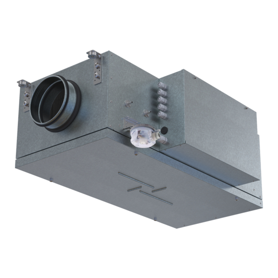
Technical specifications of the particular model are indicated on the unit casing. DESIGN AND OPERATING PRINCIPLE The unit is housed in a sound-insulated galvanized steel casing (item 1). The unit casing has 4 mounting brackets with anti- vibration connectors for ceiling or wall mounting (item 5). The air flow direction is indicated by the arrow on the fan casing. - Page 10 MPA 300/400/700/1000/1500/2000/3000/4000 E EC A30/31/32 TOP VIEW TOP VIEW MPA ... L MPA ... L MPA ... R MPA ... R The figure below shows the internals of the left and right version of the units with the removable cover removed. The air flow direction is indicated by the arrows.
- Page 11 VIEW FROM THE MAINTENANCE SIDE MPA ... L MPA ... R www.ventilation-system.com...
- Page 12 MPA 300/400/700/1000/1500/2000/3000/4000 E EC A30/31/32 The unit supplies heated and filtered outdoor air into the room. The unit uses a frameless centrifugal fan directly driven by an external rotor motor. The fan impeller blades are curved backwards. The motor has built-in thermal protection and requires no maintenance. After filtration, the air passes through the block of heaters.
-
Page 13: Mounting And Set-Up
WHILE INSTALLING THE UNIT ENSURE CONVENIENT ACCESS FOR SUBSEQUENT MAINTENANCE AND REPAIR Units MPA 300 E EC A30/31/32, MPA 400 E EC A30/31/32, MPA 700 E EC A30/31/32 have spigots for connecting to air ducts with round cross-section. Units MPA 1000 E EC A30/31/32, MPA 1500 E EC A30/31/32, MPA 2000 E EC A30/31/32, MPA 3000 E EC A30/31/32, MPA 4000 E EC A30/31/32 are installed into a system of rectangular air ducts that are connected either directly to the unit casing or through the side panels. - Page 14 MPA 300/400/700/1000/1500/2000/3000/4000 E EC A30/31/32 Moving the control unit to the opposite side of the casing If you want to move the control unit before connecting the unit to the power supply and external devices, perform the below steps in the following order: 1.
-
Page 15: Connection To Power Mains
CONNECTION TO POWER MAINS DISCONNECT THE POWER SUPPLY PRIOR TO ANY OPERATIONS WITH THE UNIT. CONNECTION OF THE UNIT TO POWER MAINS IS ALLOWED BY A QUALIFIED ELECTRICIAN WITH A WORK PERMIT FOR THE ELECTRIC UNITS UP TO 1000 V AFTER CAREFUL READING OF THE PRESENT USER’S MANUAL. - Page 16 MPA 300/400/700/1000/1500/2000/3000/4000 E EC A30/31/32 To connect the power supply and external devices, unscrew the two screws on the cover of the control unit and remove the cover, as shown in the figure in the «Mounting and set-up» section. Lead the power supply cable and the cables for connecting the control panel and the outdoor temperature sensor through the cable glands in the control unit and connect them according to the wiring diagram.
- Page 17 MPA 3000 E-18,0 EC 3,15A 3,15A L1 L2 L3 SM_L SM_L1 SM_N K2:A2 K2:A1 0,5A 0,5A 3,15A 3,15A L1 L2 L3 F2 F3 F4 1 Electric shock hazard! Power input SM1*/SM2* SM1*/SM2* ~380V, 50Hz +24V GND Rx- Rx+ GND D_in +24V GND D_in 0-10V...
- Page 18 MPA 300/400/700/1000/1500/2000/3000/4000 E EC A30/31/32 MPA 3000 E-27,0 EC 3,15А 3,15A L1 L2 L3 SM_L SM_L1 SM_N K2:A2 K2:A1 0,5А 0,5A 3,15А 3,15A 1А L1 L2 L3 F3 F4 1 Electric shock hazard! Power input М2* SM1*/SM2* SM1*/SM2* ~380V, 50Hz D_in +24V GND Rx- Rx+ GND +24V GN...
- Page 19 MPA 3000 E-45,0 EC 3,15А 3,15A L1 L2 L3 SM_L SM_L1 SM_N K2:A2 K2:A1 0,5А 0,5A 1А 3,15A 3,15A L1 L2 L3 F2 F4 Electric shock hazard! М2* Power input SM1*/SM2* SM1*/SM2* ~380V, 50Hz +24V GND Rx- Rx+ GND D_in +24V GN D_in 0-10V...
- Page 20 MPA 300/400/700/1000/1500/2000/3000/4000 E EC A30/31/32 The interpretation of the designations and the characteristics of the connection cables are given in the table. Designation Name Wire type Note A3** Remote controller 5 x 0.25 mm2 th-Tune CO2 sensor or RH1 humidity sensor 3 x 0.25 mm2 CCU* Cooler control...
-
Page 21: Technical Maintenance
TECHNICAL MAINTENANCE DISCONNECT THE UNIT FROM POWER SUPPLY BEFORE ANY MAINTENANCE OPERATIONS! MAKE SURE THE UNIT IS DISCONNECTED FROM POWER MAINS BEFORE REMOVING THE PROTECTION PRIOR TO COMMENCING ANY TECHNICAL MAINTENANCE PUT UP A PROHIBITORY SIGN ON THE FAN STARTING PANEL: “DO NOT SWITCH ON! MEN AT WORK!”... -
Page 22: Troubleshooting
MPA 300/400/700/1000/1500/2000/3000/4000 E EC A30/31/32 TROUBLESHOOTING Problem Possible reasons Troubleshooting Make sure the power supply line is connected No power supply. correctly, otherwise troubleshoot a connection error. Disconnect the fan from power supply. Troubleshoot The unit does not start. Jammed motor. the motor jamming. -
Page 23: Manufacturer's Warranty
MANUFACTURER’S WARRANTY The product is in compliance with EU norms and standards on low voltage guidelines and electromagnetic compatibility. We hereby declare that the product complies with the provisions of Electromagnetic Compatibility (EMC) Directive 2014/30/EU of the European Parliament and of the Council, Low Voltage Directive (LVD) 2014/35/EU of the European Parliament and of the Council and CE-marking Council Directive 93/68/EEC. - Page 24 MPA 300/400/700/1000/1500/2000/3000/4000 E EC A30/31/32 www.ventilation-system.com...
- Page 25 www.ventilation-system.com...
- Page 26 MPA 300/400/700/1000/1500/2000/3000/4000 E EC A30/31/32 www.ventilation-system.com...
-
Page 27: Certificate Of Acceptance
CERTIFICATE OF ACCEPTANCE Unit Type Single-block air supply unit Model Serial Number Manufacture Date Quality Inspector’s Stamp SELLER INFORMATION Seller Address Phone Number E-mail Purchase Date This is to certify acceptance of the complete unit delivery with the user’s manual. The warranty terms are acknowledged and accepted. - Page 28 V263EN-01...
Need help?
Do you have a question about the MPA 300 E EC A30 and is the answer not in the manual?
Questions and answers