
Subscribe to Our Youtube Channel
Related Manuals for Vents VKO Series


Summary of Contents for Vents VKO Series
- Page 1 ƒ VKO ƒ VKO1 ƒ M ƒ MA ƒ M1 ƒ M3 ƒ MAO1 ƒ MAO2 ƒ M1OK2 ƒ R ƒ R1 ƒ K ƒ K1 ƒ PF ƒ PF1 ƒ F ƒ F1 ƒ D ƒ D1 ƒ LD ƒ...
-
Page 2: Table Of Contents
CONTENTS Delivery set ................................................6 Brief description ..............................................7 Operation guidelines ............................................7 Product sales ................................................. 7 Designation key ..............................................8 Mounting and set-up ............................................9 Electronics operation algorithm ......................................20 Troubleshooting ..............................................24 Maintenance ................................................ 27 THE PRODUCT MUST BE DISPOSED SEPARATELY AT THE END OF ITS SERVICE LIFE. DO NOT DISPOSE THE UNIT AS UNSORTED DOMESTIC WASTE. - Page 3 This user’s manual is a main operating document intended for technical, maintenance, and operating staff. The manual contains information about purpose, technical details, operating principle, design, and installation of the Vents VKO, VKO1, M, MA, M1, M3, MAO1, MAO2, M1OK2, R, R1, K, K1, PF, PF1, F, F1, D, D1, LD, LD1, S, S1, X, X1, Xstar, Silenta-M, Silenta-S unit and all its modifications.
- Page 4 FOLLOW THE USER’S MANUAL REQUIREMENTS TO ENSURE DURABLE AND TROUBLE-FREE OPERATION OF THE UNIT. Disconnect the unit from power supply prior to any connection, servicing, maintenance, and repair operations. Only qualified electricians with a work permit for electrical units up to 1000 V are allowed for installation and maintenance. The present user’s manual should be carefully read before beginning works.
- Page 5 • Do not use the unit in a hazardous or explosive environment containing spirits, gasoline, insecticides, etc. • Do not close or block the intake or extract vents in order to ensure the efficient air flow. • Do not sit on the unit and do not put objects on it.
-
Page 6: Delivery Set
and above and persons with reduced physical, sensory, or mental capabilities or no experience and knowledge provided that they have been given supervision or instruction regarding safe use of the unit and understand the risks involved. • Do not allow children to play with the unit. DELIVERY SET –... -
Page 7: Brief Description
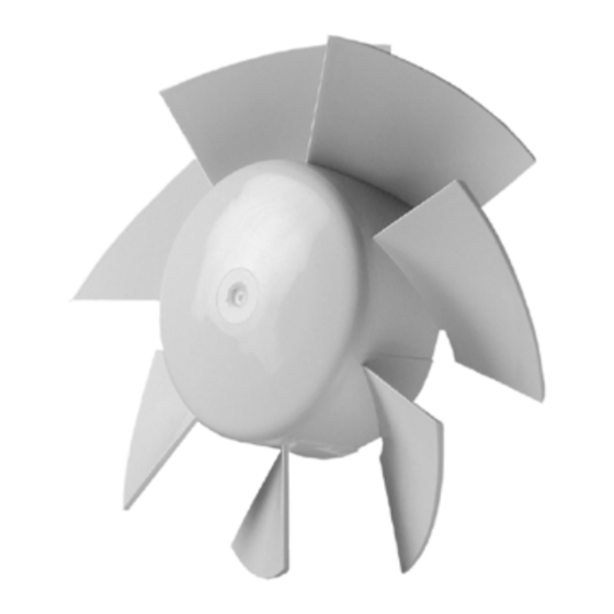
BRIEF DESCRIPTION The product is an axial fan for exhaust ventilation of small and medium-sized premises. The fans of the VKO/VKO1 series can be used for both supply and exhaust ventilation and are installed in the ventilation duct. The fan (except for the VKO/VKO1/MAO/M1OK series) is designed for wall or ceiling mounting. The fans of the VKO/VKO1 series are designed for installation in the ventilation duct. -
Page 8: Designation Key
DESIGNATION KEY Vents 100 LD A B K L Modifications _ – standard L – motor on ball bearings Turbo – high-powered motor 12 – motor with 12 V/50 Hz rated voltage Press – high pressure impeller K – non-return valve Additional options V –... -
Page 9: Mounting And Set-Up
MOUNTING AND SET-UP The designation of the fan, schematic representation of its appearance, overall and mounting dimensions, as well as design features are given below. VKO, VKO1 Model А 100 VKO/VKO1 91/113 125 VKO/VKO1 93/118 150 VKO/VKO1 108/128 The VKOk and VKO1k models are equipped with a mounting bracket for mounting on a flat surface. - Page 10 MAO1, MAO2, M1OK2 Model А 125 MAO1 – – 125 MAO2 – 150 MAO1 – – 150 M1OK2 – M3, F, F1 Model А 100 M3 125 M3 150 M3 100 F/F1 104/128 125 F/F1 110/134...
- Page 11 K, K1, D, D1, M, MA, M1, LD, LD1, S, S1, PF, PF1, X, X1, Xstar, R, R1, Silenta-M, Silenta-S Model А 100 K/K1 105/109 15/19 125 K/K1 112/116 15/19 150 K 100 D/D1 108/93 12,5 120 D 125 D/D1 114/96 12,5 150 D...
- Page 12 100 X 125 X 150 X 100 X1 11,5 120 X1 12,5 125 X1 12,5 150 X1 100 Xstar 125 Xstar 150 Xstar 100 R 100 R1 100 Silenta-M 88,5 125 Silenta-M 150 Silenta-M 25,5 100 Silenta-S 120 Silenta-S 125 Silenta-S 150 Silenta-S For fans with a K option, the overall length of the outlet pipe increases by 14 mm.
- Page 13 The fan shown in the figures may slightly differ from your model, while the installation sequence is maintained. The fan is designed for wall or ceiling mounting with direct air exhaust to the ventilation shaft or into the round air duct of matching diameter.
- Page 14 K/K1/PF/PF1/F/F1 series...
- Page 15 M/M1/M3/МА/Silenta-M series...
- Page 16 MAO/M1OK series 180 mm 150MAO1 160 mm 125M1OK2 125MAO1 125MAO2...
- Page 17 D/D1/LD/LD1/S/S1/X/X1/Xstar/Silenta-S series...
- Page 19 R/R1 series...
-
Page 20: Electronics Operation Algorithm
ELECTRONICS OPERATION ALGORITHM The fan with the T timer activates upon control voltage application to input LT (ST, SL) by an external switch (e.g. indoor light switch). After the control voltage is off, the fan continues to operate within the set time period adjustable from 2 to 30 minutes by the timer. - Page 21 The fan with the timer and the TR motion sensor – the fan starts when a person moves at a distance of 1 to 4 meters with a horizontal viewing angle of the sensor of 100°. After the movement stops, the fan continues to operate within the set time period adjustable from 2 to 30 minutes by the timer.
- Page 22 Wiring diagram for a fan equipped with a timer/timer and a humidity sensor, without a built-in switch. L(~) LT (ST) N (~) 220-240 V (12 V) Wiring diagram of the Xstar fan with separate switching on of the fan and the built-in lamp. L(~) 220-240 V (12 V) N(~)
- Page 23 For T, TH and TR timers VKO1/F1/PF1 R/R1 D/D1/S/S1/LD/X/X1/Silenta-S M/M1/M3/MA/MAO/M1OK2/Silenta-M For T1 timers M/M1/M3/MA/MAO/M1OK2/Silenta-M D/D1/S/S1/LD/X/X1/Silenta-S Jumper Jumper...
-
Page 24: Troubleshooting
TROUBLESHOOTING Problem Possible reasons Troubleshooting Make sure the power supply line No power supply. is connected correctly, otherwise When the unit is connected to power troubleshoot the connection error. mains, the fan does not rotate and does not respond to any controls. Internal connection fault. - Page 25 MANUFACTURER’S WARRANTY The product is in compliance with EU norms and standards on low voltage guidelines and electromagnetic compatibility. We hereby declare that the product complies with the provisions of Electromagnetic Compatibility (EMC) Directive 2014/30/ EU of the European Parliament and of the Council, Low Voltage Directive (LVD) 2014/35/EU of the European Parliament and of the Council and CE-marking Council Directive 93/68/EEC.
- Page 26 • Replacement and use of any assemblies, parts and components not approved by the manufacturer. • Unit misuse. • Violation of the unit installation regulations by the user. • Violation of the unit control regulations by the user. • Unit connection to power mains with a voltage different from the one stated in the user's manual. •...
-
Page 27: Maintenance
MAINTENANCE Disconnect the fan from power supply prior to maintenance and servicing operations. The fan surfaces must be regularly cleaned from dirt and dust. To clean the fan, use a soft cloth or a brush wetted in a mild detergent solution. Do not allow water or liquid come into contact with electric components. - Page 28 Certificate of acceptance VKO1 Quality Inspector’s Stamp MAO1 MAO2 Turbo M1OK2 Sold by (name and stamp of the seller) Vents К Manufacture Date Press Purchase Date Xstar Silenta-M Silenta-S The fan is recognized as serviceable. V01EN_16-01...
Need help?
Do you have a question about the VKO Series and is the answer not in the manual?
Questions and answers