
Related Manuals for Vents VENTS TT Series


Summary of Contents for Vents VENTS TT Series
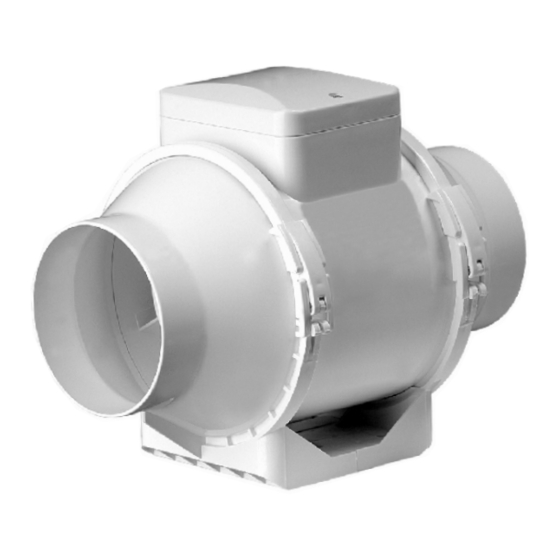
- Page 1 INLINE MIXED-FLOW FANS VENTS TT U S E R ' S M A N U A L www.ventilation-system.com 2012...
- Page 2 WARNING Any electric connections, adjustment, servicing and repair works are allowed only after the unit is disconnected from power mains. Mounting and maintenance are allowed only by duly qualified electricians with valid electrical work permit for electric units up to 1000 V. The single-phase power grid must comply with the acting local electrical norms and standards.
-
Page 3: Delivery Set
VENTS TT XXX Un (U1n) - the fan is equipped with a speed controller with electronic thermostat, external temperature sensor fixed on 4 m power cord with a plug (fig. 31); VENTS TT XXX P - the fan is equipped with a speed controller and power cord with a plug (fig. 32). XXX - spigot diameter. -
Page 4: Operation Rules
WARNING OPERATION RULES The fan is rated for connection to AC 220-240V, 50/60 Hz single phase power mains. The fan is designed for continuous operation always connected to the power mains. Air flow direction in the system must match the direction of the arrow on the fan casing. Ingress protection rating from access to dangerous parts and water penetration is IPX4. - Page 5 To set the fan speed (air capacity) rotate the speed control knob in the same way. The fan operating logic may be based on temperature or timer indications: - temperature-based operating logic (model TT XXX U) is used to keep air temperature to within 2°C. In this case the fan switches are rare.
-
Page 6: Maintenance
Designation of the automatic circuit Terminal designation: Automatic breaker on the wiring diagram circuit breaker L1 - minimum speed terminal; L2 - maximum speed terminal; QF - automatic circuit breaker; S2 - external speed switch; ST - external switch (i.e. light switch); Designation of the external X - input terminal block. - Page 7 In case of any malfunction of the product through the fault of the Manufacturing company within the warranty period (service life), the customer shall have the right to elimination of the manufacturing defects by means of warranty servicing performed free of charge. The warranty servicing implies performance of activities related to elimination of defects in the product aimed to provide intended use of the product by the customer.
- Page 8 - i n case of performing repair of the product by third persons unauthorized by the manufacturing company; - in case of warranty period (service life) expiry; - in case of the customer's violating transportation rules assuring prevention of damaging and/or destruction of the product;...
- Page 9 min 1 ì...
- Page 10 MOUNTING...
- Page 12 TT 100/125 MAX / MIN TT 125S/150/160 MAX / MIN...
- Page 13 TT 100 T/125 T/125SТ/150 T/160 T MAX / MIN...
- Page 15 2 min 30 min Õ Õ STOP...
- Page 16 Thermostat control knob ТТ U (U1) ТТ Un (U1n) Speed control knob 20°C 30°C Speed control knob...
- Page 20 ACCEPTANCE INFORMATION Fan is ready for using. Acceptance stamp Date of production 125S Т Sold (name of trade enterprise and stamp of the shop) Date of sale V10EN-08 www.ventilation-system.com...
Need help?
Do you have a question about the VENTS TT Series and is the answer not in the manual?
Questions and answers