Table of Contents
Advertisement
Quick Links
Advertisement
Table of Contents

Related Manuals for Vents TT Series


Summary of Contents for Vents TT Series
- Page 1 CENTRIFUGAL INLINE FAN USER’S MANUAL www.ventilation-system.com...
-
Page 2: Table Of Contents
CONTENTS Delivery set ..........................................6 Brief description ........................................6 Fan modifications .........................................6 Operation guidelines ......................................7 Designation key ........................................8 Mounting ..........................................9 Control logic ..........................................10 Maintenance ...........................................12 Transportation and storage rules ................................12 Manufacturer’s warranty ....................................13... - Page 3 This user’s manual is a main operating document intended for technical, maintenance, and operating staff. The manual contains information about purpose, technical details, operating principle, design, and installation of the TT unit and all its modifications. Technical and maintenance staff must have theoretical and practical training in the field of ventilation systems and should be able to perform works in accordance with workplace safety rules as well as construction norms and standards applicable in the territory of the country.
- Page 4 FOLLOW THE USER’S MANUAL REQUIREMENTS TO ENSURE DURABLE AND TROUBLE-FREE OPERATION OF THE UNIT. Disconnect the unit from power supply prior to any connection, servicing, maintenance, and repair operations. Only qualified electricians with a work permit for electrical units up to 1000 V are allowed for installation and maintenance.
- Page 5 • Do not use the unit in a hazardous or explosive environment containing spirits, gasoline, insecticides, etc. • Do not close or block the intake or extract vents in order to ensure the efficient air flow. • Do not sit on the unit and do not put objects on it.
-
Page 6: Delivery Set
VENTS TT XXX RV: model with integrated speed switch and power cable with plug (Fig. 32) VENTS TT XXX T: model with turn-off delay timer adjustable from 2 to 30 minutes (Fig. 31) VENTS TT XXX U(U1): model with a speed controller with electronic thermostat, integrated temperature sensor and power cable with plug (Fig. -
Page 7: Operation Guidelines
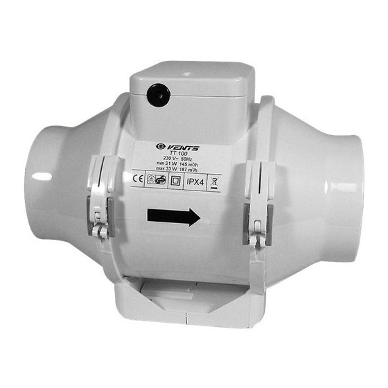
OPERATION GUIDELINES The fan is rated for connection to single-phase ac 220-240 V/ 50 (60) Hz power mains. The unit is rated for continuous operation. The arrow on the fan casing must match the air direction in the system. Ingress protection rating against access to hazardous parts and water ingress is IPX4. The fan is rated for operation at the ambient air temperature from +1 °C up to +45 °C. -
Page 8: Designation Key
DESIGNATION KEY Modifications: T: timer U: electronic temperature-dependent control unit, integrated duct temperature sensor, 0.4 m power cable. Un: electronic temperature-based control unit, external temperature sensor, 0.4 m power cable. U1: electronic timer-based control unit, integrated duct temperature sensor, 0.4 m power cable. -
Page 9: Mounting
MOUNTING The fan is designed for horizontal or vertical installation on the floor, on the wall or on the ceiling (Fig. 1). The fan can be installed independently or as part of a set with parallel or in-series connection (Fig. 2). To be installed on the intake spigot side: •... -
Page 10: Control Logic
CONTROL LOGIC TT XXX T fan starts running after the external switch supplies control signal to the LT input terminal (for example, during turning the light on). After removal of the control signal the fan continues to run within the set time (adjustable with the turn-off delay timer from 2 to 30 minutes). - Page 11 The fan functioning logic may be based on temperature or timer controls: - temperature-based functioning (model TT XXX U) is used to keep air temperature to within 2 °C. In this case the fan switches are rare. The fan switches to the maximum speed as the room air temperature exceeds the set point.
-
Page 12: Maintenance
MAINTENANCE Clean the fan surfaces of dirt and dust each 6 months (Fig. 35–41). Disconnect the fan from power supply prior to any maintenance operations. For cleaning the fan use a soft cloth or a brush wetted in a mild detergent solution. Avoid water dripping on the electric components (Fig. -
Page 13: Manufacturer's Warranty
MANUFACTURER’S WARRANTY The product is in compliance with EU norms and standards on low voltage guidelines and electromagnetic compatibility. We hereby declare that the product complies with the provisions of Electromagnetic Council Directive 2014/30/EU, Low Voltage Directive 2014/35/EU and CE-marking Directive 93/68/EEC. This certificate is issued following test carried out on samples of the product referred to above. - Page 14 • External damage to the unit casing (excluding external modifications as required for installation) and internal components caused by the user. • Redesign or engineering changes to the unit. • Replacement and use of any assemblies, parts and components not approved by the manufacturer. •...
- Page 15 min 1 m...
- Page 18 TT 100/125 MAX / MIN TT 125S/150/160 MAX / MIN...
- Page 19 TT XXX T Terminal box for 5 contacts Terminal box for 4 contacts MAX / MIN Terminal box for 5 contacts Terminal box for 4 contacts Terminal box for 4 contacts Terminal box for 5 contacts...
- Page 20 TT 250, TT 315...
- Page 22 2 min 30 min STOP...
- Page 23 Temperature control knob TT U (U1) TT Un (U1n) Speed control knob m in m a x 2 0 °C 3 0 °C Speed control knob m in m a x...
- Page 25 و ﻮ...
- Page 27 Approval mark Sold (name and stamp of the seller) Manufacturing date Sales date...
- Page 28 Certificate of acceptance 125C The fan is recognized as serviceable. V10EN-10...
Need help?
Do you have a question about the TT Series and is the answer not in the manual?
Questions and answers