Table of Contents

Subscribe to Our Youtube Channel
Related Manuals for emmeti EIDH 22M Series


Summary of Contents for emmeti EIDH 22M Series
- Page 1 UNITÀ INTERNA CLIMATIZZATORE CANALIZZATO AIR CONDITIONER INDOOR UNIT DUCT MODELLO/MODEL EIDH-XX22M MANUALE INSTALLAZIONE ED ISTRUZIONI PER L’USO IT IT USE AND INSTALLATION MANUAL...
- Page 2 ® All rights reserved. No part of this pubblication may be reproduced or distri- ® Tutti i diritti sono riservati. Nessuna parte della pubblicazione può essere buted without written permission from Emmeti. riprodotta o diffusa senza il permesso scritto da Emmeti. Warning! Attenzione! Keep these manuals in a dry place avoiding in this way to spoil them.
- Page 3 IT IT INDICE 1. PRESENTAZIONE DEL PRODOTTO ..4 11. SMALTIMENTO ......37 1.1 Introduzione alla climatizzazione 11.1 Nota informativa RAEE 1.2 Il circuito frigorifero 11.2 Norme di smaltimento del vecchio climatizzatore 1.3 Composizione del climatizzatore 11.3 Norme di smaltimento dell’imballaggio del nuovo climatizzatore 1.4 Unità...
-
Page 4: Presentazione Del Prodotto
IT IT 1. PRESENTAZIONE DEL PRODOTTO 1.1 Introduzione alla climatizzazione 1.3 Composizione del climatizzatore La funzione dei climatizzatori è quella di creare, negli ambienti in cui sono I climatizzatori sono della tipologia “Split System” con scambio termico installati, le condizioni ottimali di temperatura e di umidità che soddisfano aria-aria. - Page 5 IT IT 1. PRESENTAZIONE DEL PRODOTTO 1.6 Tabella identificazione prodotti La seguente tabella serve ad identificare il climatizzatore completo o la singola unità acquistata: Grandezza Unità Tipo Modello kBtu/h EIFH-3622 EIFH-4222 Pavimento / Soffitto EIFH-4822 EIFH-6022 EICH-3622 EICH-4222 Cassette EICH-4822 Interna EICH-6022 EIDH-3622M...
- Page 6 IT IT 2. AVVERTENZE Significato dei simboli 2.1 Attenzioni e pericoli Prima di continuare le operazioni leggere il manuale per l'operatore Prima di utilizzare il climatizzatore leggere attentamente il presente Prima di eseguire interventi di manutenzione e riparazione, manuale di istruzioni. Il produttore declina ogni responsabilità per even- leggere il manuale di manutenzione tuali danni derivanti dalla non osservanza delle seguenti avvertenze.
- Page 7 IT IT 2. AVVERTENZE Qualora si verifichi un malfunzionamento è consigliabile spegnere prima Utilizzare il climatizzatore solo per cli- il condizionatore col comando a filo, prima di scollegare l'alimentazione matizzare il locale. elettrica. Non usare il condizionatore per altri scopi, es. conservazione e protezione di cibo, animali, piante, strumenti di precisione come anche opere d’arte, perché...
- Page 8 IT IT 3. INFORMAZIONI IMPORTANTI 3.1 Conformità ai regolamenti 3.2 Grado di protezione degli involucri (Codice IP) I climatizzatori sono conformi alle direttive europee: 2014/30/UE relativa alla compatibilità elettromagnetica IP20 Unità interna 2014/35/UE relativa alla bassa tensione IP24 Unità esterna 2012/19/UE RAEE riguardante i rifiuti di apparecchiature elettriche ed elettroniche.
- Page 9 IT IT 3. INFORMAZIONI IMPORTANTI 3.4 Estratto della scheda di sicurezza refrigerante R 32 Gas refrigerante Tipo R 32 Denominazione Difluorometano 3.0 Indicazioni dei pericoli H220: Gas altamente infiammabile. H280: Contiene gas sotto pressione; può esplodere se riscaldato. DESCRIZIONE DELLE MISURE DI PRIMO SOCCORSO In alta concentrazione può...
- Page 10 IT IT 3. INFORMAZIONI IMPORTANTI Stabilità chimica Stabile in condizioni normali. Materiali incompatibili Aria e ossidanti. Per la compatibilità con i materiali, vedere l’ultima versione della ISO-1114. Prodotti di decomposizione Nelle normali condizioni di stoccaggio ed uso, non si dovrebbero formare prodotti di decomposizione pericolosi. pericolosi INFORMAZIONI TOSSICOLOGICHE Tossicità...
-
Page 11: Movimentazione E Trasporto
IT IT 4. MOVIMENTAZIONE E TRASPORTO Movimentazione di unità pesanti Disimballo Le operazioni di disimballo devono essere eseguite con cura, al fine di non danneggiare l’involucro delle unità, se si opera con coltelli o taglierini per aprire l’imballo in cartone. ATTENZIONE Dopo aver tolto l’imballo assicurarsi dell’integrità... -
Page 12: Posizionamento Dell'unità
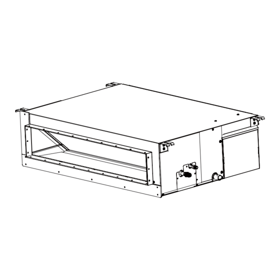
IT IT 5. POSIZIONAMENTO DELL'UNITÀ Il condizionatore deve essere collocato in un luogo ben ventilato e facilmente (e) In veicoli o imbarcazioni. accessibile. (f) In cucine con molti fumi di oli ed alta percentuale d’ umidità. Il condizionatore non deve essere collocato nei luoghi che seguono: (g) Vicino a macchine che emettono onde elettromagnetiche. - Page 13 IT IT 5. POSIZIONAMENTO DELL'UNITÀ 1. DESCRIZIONE DEI COMPONENTI 5.2 Dati dimensionali unità interna 1562 1500 1392 1378 128 158...
-
Page 14: Distanze Minime
IT IT 5. POSIZIONAMENTO DELL'UNITÀ 5.3 Distanze minime Dimensione del foro sul soffitto e posizione dei bulloni per sostegno dell'unità. 1562 Posizione del bullone di sospensione 2012 Quote in mm Dimensioni foro soffitto 2072 Dimensioni del pannello 1. Prevedere la porta per la manutenzione, necessaria quando il soffitto non è... -
Page 15: Installazione Dell'unità Interna
- Operazioni non adeguate possono provocare gravi danni all'utente. - La lista dei centri assistenza è disponibile nel sito web www.emmeti.com. 6.1 Fissaggio dell'unità ai bulloni di ancoraggio (Sospensione) - Inserire le staffe di ancoraggio dell'unità interna sui bulloni di ancorag- Bulloni di ancoraggio gio per appendere l'unità. - Page 16 IT IT IT IT 6. INSTALLAZIONE DELL'UNITÀ INTERNA 6.2 Installazione delle condotte dell'aria - Ciascuna delle condotte per la mandata e l'aspirazione dell’aria devono essere fissate sul pannello prefabbricato del soffitto usando staffe di metallo. La distanza raccomandata tra il bordo della condotta di aspirazione dell’aria e la parete deve essere superiore a 150 mm. Unità...
- Page 17 IT IT IT IT 6. INSTALLAZIONE DELL'UNITÀ INTERNA 1. DESCRIZIONE DEI COMPONENTI 6.4 Installazione del tubo di scarico condensa Per le unità con pompa scarico condensa utilizzare un tubo in PVC rigido che può essere acquistato localmente. Collegare saldamente il tubo in PVC alla presa di scarico utilizzando una fascetta appropriata.
- Page 18 IT IT 6. INSTALLAZIONE DELL'UNITÀ INTERNA Controllo dello scarico Isolamento delle tubazioni Durante il funzionamento iniziale, verificare che non ci siano perdite tra i Prima di eseguire le operazioni di cartellatura del tubo è indispensabile collegamenti dei tubi mentre l'acqua è scaricata, anche durante l’inverno. isolarlo e poi inserire i bocchettoni sul tubo.
-
Page 19: Allacciamento Elettrico
IT IT 1. DESCRIZIONE DEI COMPONENTI 6. INSTALLAZIONE DELL'UNITÀ INTERNA Alimentazione delle unità Connessione dei tubi ai raccordi Connettere le tubazioni ai raccordi delle unità. L'alimentazione viene portata sull' unità esterna. Per il serraggio stringere i bocchettoni con una coppia pari a: Utilizzare una fonte di alimentazione ad uso esclusivo del climatizzatore, con interruttore magnetotermico/differenziale dedicato. - Page 20 IT IT 6. INSTALLAZIONE DELL'UNITÀ INTERNA - Prevedere l’uso di una guaina di protezione dei cavi esposti all’esterno. - È consigliabile predisporre i cavi con un percorso antigoccia onde evitare possibili infiltrazioni d’acqua nell’unità esterna. - Unire il cavo elettrico di collegamento delle due unità alle tubazioni refrigeranti e avvolgerle con un nastro rinforzato, possibilmente allu- minato.
- Page 21 IT IT IT IT 1. DESCRIZIONE DEI COMPONENTI 7. CONTROLLO A FILO Interfaccia Tasti Tasto ON/OFF MODE Tasto Mode: Premi questo tasto per eseguire il cambio di modalità. Tasto Fan: Premi questo tasto per regolare la velocità della ventilazione. Tasto Up/Down: Premere questo tasto per regolare la temperatura nell'interfaccia principale e il valore di altri parametri nell'altra interfaccia.
-
Page 22: Timer On/Off
IT IT 7. CONTROLLO A FILO Icone Visualizzazione dell'orologio, visualizzazione dei parametri Timer ON/OFF Visualizzazione della temperatura ROOM/SET Visualizzazione dell'umidità ROOM/SET Icona Errore Visualizzazione del deflettore aria su quattro lati (valido solo per parte dei modelli) Swing Up/Down - Oscillazione alto/basso Swing Left/Right Oscillazione sinistra/destra (valido solo per parte dei modelli) Icona delle impostazioni Modalità... - Page 23 IT IT IT IT 1. DESCRIZIONE DEI COMPONENTI 8. CONTROLLO A FILO - FUNZIONI Orologio Descrizione delle funzioni di base (1) Il controllo a filo utilizza l'orologio a 24 ore. L'impostazione predefinita Funzione di base Modalità di funzionamento è 12:00 quando il controllo a filo viene acceso per la prima volta. Premi il tasto ON/OFF (2) Quando la retroilluminazione è...
- Page 24 IT IT 8. CONTROLLO A FILO - FUNZIONI Circolazione delle funzioni Oscillazione (swing) Funzione UP/DOWN flusso d'aria su/giù (valido solo per alcuni modelli) Premere il tasto MENU (se si tratta della cassetta modello a 4 vie/ circolare, è necessario premere il tasto MENU per 5 secondi) per (1) Premere il tasto MENU per accedere alla circolazione delle funzioni, accedere alla circolazione delle funzioni, utilizzare i tasti utilizzare i tasti...
-
Page 25: Risparmio Energetico
IT IT 8. CONTROLLO A FILO - FUNZIONI Funzione Ventilazione e recupero di calore 2 In modalità riscaldamento, impostare la temperatura a 16°C, (1) Premere il tasto MENU per accedere alla circolazione delle funzioni, premere a lungo il tasto FAN per 5 secondi per accedere al parametro di utilizzare i tasti per passare da una funzione all'altra. - Page 26 IT IT IT IT 8. CONTROLLO A FILO - FUNZIONI Rilevamento del movimento Visualizzazione malfunzionamento (valido solo per una parte dei modelli) (1) In caso di malfunzionamento, l'interfaccia principale visualizzerà l'i- cona (1) La funzione di rilevamento del movimento include (Segui): la direzione dell'oscillazione segue le persone.
-
Page 27: Blocco Bambini
IT IT IT IT 1. DESCRIZIONE DEI COMPONENTI 8. CONTROLLO A FILO - FUNZIONI Blocco bambini Unità esterna silenziosa (1) Premere i tasti e MENU per 5 secondi per impostare/annullare il (1) Premere il tasto MENU per accedere alla circolazione delle funzioni, blocco bambini. - Page 28 IT IT IT IT 8. CONTROLLO A FILO - FUNZIONI Comunicazione con il controller centrale VIP (valido solo per alcuni modelli) (1) Dopo che il controller riceve il comando dal controller centralizzato. (1) Metodo di impostazione: tenere premuto il tasto MENU + per 5 secondi per accedere alle impostazioni avanzate, il numero dell'unità...
- Page 29 IT IT IT IT 1. DESCRIZIONE DEI COMPONENTI 8. CONTROLLO A FILO - FUNZIONI VISTA POSTERIORE CONTROLLO A FILO Premere per aprire Connettore a 3 poli DIP SWITCH Posizione Impostazioni Funzione SWITCH 2 ON/OFF predefinite Comando a filo slave Comando a filo master Visualizza la temperatura ambiente Non visualizza la temperatura ambiente Raccogliere la temperatura ambiente dal PCB dell'unità...
-
Page 30: Collegamenti Elettrici
IT IT 8. CONTROLLO A FILO - FUNZIONI Collegamenti elettrici Interna 1 Interna 2 Interna 15 Interna 16 Unità interna N (unità master) Cavo con polarità. Comando a filo Interna 1 Interna 1 Cavo polare Cavo polare Cavo polare Controllo a filo Controlloo master Controllo slave Interna 1... - Page 31 IT IT IT IT 1. DESCRIZIONE DEI COMPONENTI 8. CONTROLLO A FILO - FUNZIONI Lunghezza cablaggio (m/ft) Tipologia cablaggio < 100m 0.3mm x3 cavo schermato (22AWG,3 cavi) ≥100m e <200m 0.5mm x3 cavo schermato (20AWG,3 cavi) ≥200m e <300m 0.75mm x3 cavo schermato (18AWG,3 cavi) Premere in questa zona per separare...
- Page 32 IT IT 1. DESCRIZIONE DEI COMPONENTI 9. MANUTENZIONE DEL CLIMATIZZATORE Per un uso corretto del climatizzatore Impostare la temperatura ambiente in modo adeguato. Non collocare ostacoli davanti alle griglie di aspirazione e di uscita. Temperatura adeguata Chiudere porte e finestre durante il funzionamento In modalità Utilizzare il Timer in maniera efficace.
-
Page 33: Pulizia Dell'unità Interna
IT IT 9. MANUTENZIONE DEL CLIMATIZZATORE 1. DESCRIZIONE DEI COMPONENTI Attenzione! Tutte le operazioni di manutenzione devono essere eseguite dopo aver tolto l’alimentazione elettrica al climatizzatore. Spegnere il condizionatore prima con il telecomando e poi scollegare l’alimentazione elettrica. 9.1 Pulizia del controllo a filo - Per pulire il controllo a filo utilizzare un panno asciutto, non utilizzate prodotti per la pulizia dei vetri o detergenti. - Page 34 IT IT 9. MANUTENZIONE DEL CLIMATIZZATORE 9.6 Al riavvio del climatizzatore 9.4 Verifica dello scarico dopo una lunga inattività dell’acqua di condensa - Rimuovere la copertura protettiva dall’unità esterna e verificarne la Nell’uso estivo del climatizzatore verificare il corretto drenaggio dell’ac- pulizia.
- Page 35 IT IT 1. DESCRIZIONE DEI COMPONENTI 1. DESCRIZIONE DEI COMPONENTI 10. ANOMALIE DI FUNZIONAMENTO In particolari condizioni il climatizzatore può presentare anomalie di funzionamento che spesso sono apparenti o determinate da cause accidentali o, più spesso, banali. Attenzione! Prima di richiedere l’intervento del centro assistenza è consigliabile eseguire facili controlli sia per usufruire in continuazione e al meglio delle prestazioni del climatizzatore, sia per evitare inutili interventi di assistenza.
-
Page 36: Anomalie Di Funzionamento
IT IT 10. ANOMALIE DI FUNZIONAMENTO UNITA’ INTERNA CANALIZZATA EIDH-3622M , EIDH-4222M , EIDH-4822M , EIDH-6022M N° Lampeggi LED PCB Display Malfunzionamento Possibile causa LED4 LED3 Malfunzionamento del sensore di Sensore disconnesso, danneggiato, temperatura interna posizione errata, cortocircuito Malfunzionamento del sensore di Sensore disconnesso, danneggiato, temperatura della tubazione posizione errata, cortocircuito... - Page 37 IT IT 11. SMALTIMENTO 1. DESCRIZIONE DEI COMPONENTI 11.1 Nota informativa RAEE 11.3 Norme di smaltimento dell'imballaggio del Ai sensi dell’art. 26 del Decreto Legislativo 14 marzo 2014, n. 49 nuovo climatizzatore “Attuazione della Direttiva 2012/19/UE sui rifiuti di apparecchia- ture elettriche ed elettroniche (RAEE)”.
- Page 38 IT IT IT IT 1. DESCRIZIONE DEI COMPONENTI 12. SCHEMI ELETTRICI - WIRING DIAGRAM 1. DESCRIZIONE DEI COMPONENTI 12. SCHEMI ELETTRICI - WIRING DIAGRAM EIDH-3622M EIDH-3622M...
- Page 39 IT IT 12. SCHEMI ELETTRICI - WIRING DIAGRAM IT IT 12. SCHEMI ELETTRICI - WIRING DIAGRAM EIDH-4222M , EIDH-4822M , EIDH-6022M EIDH-4222M , EIDH-4822M , EIDH-6022M...
-
Page 40: Condizioni Di Garanzia
Dichiara inoltre di aver preso visione della Informativa sui dati personali disponibile anche sul sito internet di Emmeti S.p.A. EMMETI spa - Via brigata Osoppo, 166 - 33074 Vigonovo frazione di Fontanafredda (PN) - Italia - Tel.0434567911 - Fax 0434567901 - www.emmeti.com... - Page 41 INDEX 1. INTRODUCTION TO THE PRODUCT ..42 11. DISPOSAL ......... 75 1.1 Introduction to the conditioning 11.1 Information note WEEE directive 2012/19/EU 1.2 Refrigeration circuit 11.2 Disposal rules for the old air conditioner 1.3 Air conditioner composition 11.3 Disposal rules of the new air conditioner packaging 1.4 Indoor unit 1.5 Accessories supplied with the indoor unit 1.6 Products identification table...
-
Page 42: Introduction To The Product
1. INTRODUCTION TO THE PRODUCT 1.1 Introduction to conditioning 1.3 Air conditioner composition Air conditioner function is to create perfect temperature and humidity The air conditioners are of the "Split System" type with air-to-air heat conditions in the rooms they are installed, optimal conditions are able to exchange. -
Page 43: Product Identification Table
1. INTRODUCTION TO THE PRODUCT 1.6 Product identification table Through the following table you may identify the make-up of the air conditioner. Quantity- Unit Type Model kBtu/h EIFH-3622 EIFH-4222 Floor Ceiling EIFH-4822 EIFH-6022 EICH-3622 EICH-4222 Cassette EICH-4822 Indoor EICH-6022 EIDH-3622M EIDH-4222M Duct EIDH-4822M... - Page 44 2. WARNINGS Attention and dangers Meaning of the symbols Before continuing the operations, read the operator manual Before using the air conditioner please read carefully the instructions ma- nual. Producer decline every responsibility for any damage caused by the Before doing any maintenance and repair works, read non-observing of the following warnings.
- Page 45 2. WARNINGS Use the air conditioner only to con- If a device malfunction occurs, it is advisable to switch off the air condi- tioner through its remote control, before disconnecting the power supply. dition the room. Do not use the air conditioner for other purposes, for example: drying laundry, preserving food, breeding animals or cultivating vegetables.
- Page 46 3. IMPORTANT INFORMATION 3.1 Compliance with the regulations 3.2 Degree of protection provided by enclosures (IP Code) Air conditioners are conform to the European stadanrd: 2014/30/EU regarding Electromagnetic Compatibility IP20 Indoor Unit 2014/35/EU standards on Low Voltage. IP24 In accordance with the directive 2012/19/EU WEE of the European par- Outdoor unit liament, herewith we inform the users about the disposal requirements of the electrical and electronic products.
- Page 47 3. IMPORTANT INFORMATION 3.4 Extract from refrigerant gas R 32 safety data sheet Refrigerant gas R 32 Type Product Name Difluorometano 3.0 H220: Highly flammable gas. Physical hazards H280: It contains gas under pressure; it may explode when heated. FIRST AID MEASURES: In high concentrations, it may cause asphyxiation.
-
Page 48: Toxicological Information
3. IMPORTANT INFORMATION Hazardous decomposition pro- Under normal conditions of storage and use, hazardous decomposition products should not be produced. ducts TOXICOLOGICAL INFORMATION Acute toxicity by product inge- Basing on the available data, classification criteria are not met. stion Acute toxicity when the product Basing on the available data, classification criteria are not met. -
Page 49: Handling And Transport
4. HANDLING AND TRANSPORT Handling of heavy units Unpacking Unpacking operations have to be done carefully because the Outdoor part of the units has not to be damaged when knifes or cutters are used to open the carton package. ATTENTION After unpacking make sure of the unit integrity. -
Page 50: Indoor Unit Positioning
5. UNITS POSITIONING f) In kitchens with a lot of oil fumes and with high humidity percentage Air conditioner has to be placed in a well-ventilated and easy to reach place. g) Near machines issuing electromagnetic waves Air conditioner has not to be placed in the following places: h) Places with acid or alkaline fumes a) Places where there are machines oils or other oils fumes. - Page 51 5. UNITS POSITIONING 1. DESCRIZIONE DEI COMPONENTI 5.2 Dimensional data indoor unit 1562 1500 1392 1378 128 158...
-
Page 52: Minimum Distances
1. DESCRIZIONE DEI COMPONENTI 5. UNITS POSITIONING 5.3 Minimum distances Size of ceiling hole and location of bolts for unit support. 1562 Dimensions in mm Hanging bolt position 2012 Ceiling hole size 2072 Panel dimensions 1. Schedule the door for maintenance, which is required when the ceiling it is not removable. -
Page 53: Installation Of The Indoor Unit
- Repairs of an electrical nature must be performed by qualified electricians. - Improper operations may cause serious harm to the user. - You can find a list of service centres at the website www.emmeti.com Internal Unit The right installation of the air conditioner assure its efficiency... - Page 54 6. INSTALLATION OF THE INDOOR UNIT 6.2 Installation of air ducts - Each of the inlet and outlet air ducts must be fixed using metal brackets. The recommended distance between the edge of the air intake duct and the wall must be greater than 150 mm. Indoor unit Isolamento termico...
- Page 55 IT IT 6. INSTALLATION OF THE INDOOR UNIT 1. DESCRIZIONE DEI COMPONENTI For units with drain pump use rigid PVC pipe which can be purchased 6.4 Installing the condensate drain pipe locally. Securely connect the PVC pipe to the drain socket using an appropriate clamp.
-
Page 56: Refrigerating Circuit Piping
6. INSTALLATION OF THE INDOOR UNIT Checking the discharge Insulating the pipelines During initial operation, check that there are no leaks between the hose - Before carrying out the flaring of the pipe, it is essential to insulate the connections and the water is discharged, even during the winter. pipe and then fit the nuts on the pipe 6.5 Refrigerating circuit piping The connections for the refrigerating piping are sealed with a flared end... -
Page 57: Electrical Supply
1. DESCRIZIONE DEI COMPONENTI 6. INSTALLATION OF THE INDOOR UNIT Powering on the units Connecting the pipes to the fittings The power is provided on the outdoor unit. - Connect the pipes to the fittings on the unit. Use a power supply source exclusively for the air conditioner, with a dedi- -Secure by tightening the nuts to a torque of: cated circuit breaker/differential switch. - Page 58 1. DESCRIZIONE DEI COMPONENTI 1. DESCRIZIONE DEI COMPONENTI 6. INSTALLATION OF THE INDOOR UNIT - Provide to use a protection sheet for the cables exposed to the outside. - It is recommended to set the cables with a drip-proof run in order to avoid possible infiltrations of water in the outdoor unit.
-
Page 59: Interface Display
7. WIRED CONTROL 1. DESCRIZIONE DEI COMPONENTI Interface display Keys ON/OFF key MODE Mode key: Press this key to execute mode switch. Fan key: Press this key to adjust fan speed. Up/Down key: Press this key to adjust temperature in the main Interface and other parameter value in other interface. -
Page 60: Wired Control
7. WIRED CONTROL Icons Clock display , parameter display Timer ON/OFF ROOM /SET temperature display ROOM/SET humidity display Error icon Four-sided air deflector display ( Only valid for part of models) Up/Down Swing Left/Right Swing (Only valid for part of models) Set icon Auto mode Cooling mode... -
Page 61: Basic Function Description
1. DESCRIZIONE DEI COMPONENTI 8. WIRED CONTROL - FUNCTIONS Clock Basic function description (1) The controller uses 24-hour clock. The default is 12:00 when the wired Basic function Method of operation remote controller is turned on for the first time. Press the key to switch on/off ON/OFF... - Page 62 1. DESCRIZIONE DEI COMPONENTI 8. WIRED CONTROL - FUNCTIONS Function circulation Health airflow up/down function (only valid for part of models) Press MENU key (if it is the 4-way/Round-way Cassette model, you need press MENU key for 5 seconds) to enter function circulation, use (1) Press MENU key, you will enter function circulation, use key to switch between different functions.
-
Page 63: Filter Cleaning
8. WIRED CONTROL - FUNCTIONS 1. DESCRIZIONE DEI COMPONENTI Heat Reclaim Ventilation 2 In heating mode, set temperature to 16°C, long press FAN key for 5 (1) Press MENU key, you will enter function circulation, use seconds to enter energy saving parameter of heating mode setting, the to switch between different functions. -
Page 64: Malfunction Display
1. DESCRIZIONE DEI COMPONENTI 8. WIRED CONTROL - FUNCTIONS Motion sensing Malfunction Display (only valid for part of models) (1) If there is a malfunction, the main interface will display icon. (1) Motion sensing function includes (Follow): Swing direction follows people. (2) When backlight is on, long press TIME key for 10 seconds to enter (Evade): Swing direction Evades people. -
Page 65: Child Lock
8. WIRED CONTROL - FUNCTIONS 1. DESCRIZIONE DEI COMPONENTI Child lock Outdoor unit quiet (1) Press and MENU keys for 5 seconds to set / cancel child lock. (1) Press MENU key, you will enter function circulation, use to switch between different functions. When it switches to the outdoor If child lock function is set, icon will be displayed in the main interface. -
Page 66: Temperature Compensation
1. DESCRIZIONE DEI COMPONENTI 8. WIRED CONTROL - FUNCTIONS Communication with central controller VIP ( Only valid for part of models) (1) After the controller receives the command from the centralized (1) Setting method: Keep pressing the MENU key + key for 5 seconds to enter the advanced settings, the unit number is displayed in the lower controller. - Page 67 8. WIRED CONTROL - FUNCTIONS 1. DESCRIZIONE DEI COMPONENTI WIRED REMOTE CONTROLLER BACK VIEW Press this button to open the back cover of the wired remote controller Connector 3-pole DIP SWITCH ON/OFF Function Default setting SWITCH 2 station Slave wired remote controller Master wired remote controller Display ambient temperature Not display ambient temperature...
- Page 68 8. WIRED CONTROL - FUNCTIONS Wiring connections of wire controller Notice: For wired remote controller connection, please do follow the corresponding indoor unit installation manual's instruction. Wired remote controller Wiring Instruction 3. Two wired remote controllers control one indoor unit as shown Figure C. Either one of wired remote controllers can be set as the master wired remote controller and the other as the slave wired remote controller.
- Page 69 8. WIRED CONTROL - FUNCTIONS Communication wiring length (m/ft) Dimensions of wiring < 100m/328ft 0.3mm x3-core shielded wire (22AWG,3wire) ≥100m/328ft and <200m/656ft 0.5mm x3-core shielded wire (20AWG,3wire) ≥200m/656ft and <300m/984ft 0.75mm x3-core shielded wire (18AWG,3wire) Press in this area to separate the front from the base of the lid.
-
Page 70: Air Conditioner Maintenance
9. AIR CONDITIONER MAINTENANCE For correct use of the air conditioner Set the room temperature suitably. Do not place obstacles from in front of the intake and outlet grilles Suitable temperature Close doors and windows during operation in Cooling mode Use the Timer effectively In cooling mode, keep direct sunlight out... -
Page 71: Indoor Unit Cleaning
9. AIR CONDITIONER MAINTENANCE 1. DESCRIZIONE DEI COMPONENTI Attention! All maintenance operations must be carried out after having disconnected the power supply from the air conditioner. Turn off the air conditioner first with the remote control and then disconnect the power supply. 9.1 Remote control cleaning - To clean the remote control, use a dry cloth. -
Page 72: Extraordinary Maintenance
9. AIR CONDITIONER MAINTENANCE 9.4 Condensate water drain check 9.6 At the air conditioner restart after a long inactivity When using the air conditioner in the summer time check that the conden- sation water is drained correctly from the indoor unit. - Remove the protective cover from the outdoor unit and check if it is - Check the outflow of water from the end of the condensation discharge clean. - Page 73 1. DESCRIZIONE DEI COMPONENTI 1. DESCRIZIONE DEI COMPONENTI 10. ANOMALIES AND FUNCTIONING In particular conditions the air conditioner may malfunction, this is often apparently or determined by accidental or, more often, banal causes. Attention! Before requesting the intervention of the service centre is recommended to perform easy checks for both to enjoy the air conditioner continuously and at best of its performances, in order to avoid unnecessary servicing.
- Page 74 1. DESCRIZIONE DEI COMPONENTI 10. ANOMALIES AND FUNCTIONING DUCT INDOOR UNIT EIDH-3622M , EIDH-4222M , EIDH-4822M , EIDH-6022M LED flash times LR.Recever of indoor PCB Contents of malfunction Possible reasons digital display LED4 LED3 Malfunction of indoor unit ambient Sensor disconected, or broken, or at wrong temperature sensor position, or short circuit Malfunction of indoor unit piping...
- Page 75 11. DISPOSAL 1. DESCRIZIONE DEI COMPONENTI 11.3 Disposal rules for the new air conditioner 11.1 INFORMATION NOTE WEEE packaging Directive 2012/19 / EU All of the air conditioner packing materials can be disposed of without harming the environment. The cardboard box must be cut into pieces and delivered to a paper collection container.
-
Page 76: General Terms Of Warranty
8 days of their discovery, unless otherwise agreed in writing and confirmed by both the parties. EMMETI spa Via brigata Osoppo, 166 - 33074 Vigonovo frazione di Fontanafredda (PN) - Italia - Tel.0434567911 - Fax0434567901 - www.emmeti.com... - Page 77 NOTE...
- Page 78 NOTE...
- Page 79 NOTE...
- Page 80 Rispetta l’ambiente! Per il corretto smaltimento, i diversi materiali devono essere separati e conferiti secondo la normativa vigente. Respect the environment! For a correct disposal, the different materials must be divided and collected according to the regulations in force. CARTA PAP22 F F .
Need help?
Do you have a question about the EIDH 22M Series and is the answer not in the manual?
Questions and answers