Sign In
Upload
Manuals
Brands
Amazone Manuals
Farm Equipment
Cataya 3000 Super
Amazone Cataya 3000 Super Manuals
Manuals and User Guides for Amazone Cataya 3000 Super. We have
4
Amazone Cataya 3000 Super manuals available for free PDF download: Operating Manual, Original Operating Manual
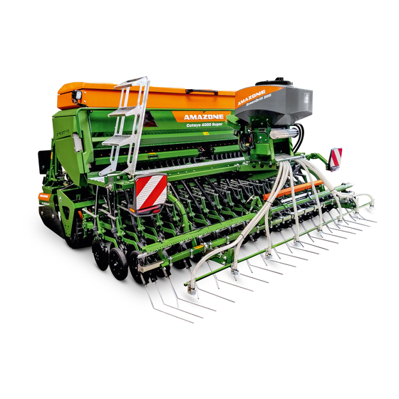
Amazone Cataya 3000 Super Operating Manual (252 pages)
Pack top seed drill
Brand:
Amazone
| Category:
Farm Equipment
| Size: 48 MB
Table of Contents
Table of Contents
5
1 User Information
10
Purpose of the Document
10
Locations in the Operating Manual
10
Diagrams
10
2 General Safety Instructions
12
Obligations and Liability
12
Representation of Safety Symbols
14
Organisational Measures
15
Safety and Protective Equipment
15
Informal Safety Measures
15
User Training
16
Safety Measures in Normal Operation
17
Danger from Residual Energy
17
Maintenance and Repair Work, Fault Elimination
17
Design Changes
18
Spare and Wear Parts and Aids
19
Cleaning and Disposal
19
User Workstation
19
Warning Symbols and Other Labels on the Implement
20
Position of Warning Symbols
26
Dangers in Case of Non-Compliance with the Safety Instructions
28
Safety-Conscious Working
28
Safety Information for Users
29
General Safety Instructions and Accident Prevention Instructions
29
Hydraulic System
33
Electrical System
34
Mounted Implements
35
Operation of the Seed Drill
36
Cleaning, Maintenance and Repair
36
3 Loading and Unloading the Implement Upon Delivery
37
4 Product Description
39
Components of the AMAZONE Seeding Combination
39
Equipment Variations of the Cataya Pack Top Seed Drill
40
Assembly Groups of the Cataya Pack Top Seed Drill
43
Safety and Protective Equipment
45
Overview - Supply Cable / Hydraulic Hose Lines
47
Supply Cable
47
Identification of the Hydraulic Hose Lines
47
Type of Actuation of the Tractor Control Units
47
Connection and Function of the Tractor Control Units
48
Comfort Hydraulic System - Implements with ISOBUS System
49
Traffic Safety Equipment
50
Intended Use
51
Approved AMAZONE Implement Combinations
52
Danger Areas and Danger Points
53
Rating Plate and CE Mark
54
Technical Data
55
Noise Production Data
55
Technical Data for Calculating the Tractor Weight and the Tractor Axle Loads
56
Required Tractor Equipment
57
5 Layout and Function
58
AMAZONE Amalog+ Control Terminal
61
AMAZONE Amadrill 2 Control Terminal
61
AMAZONE Calibration Button
62
Control Terminal for Implements with ISOBUS System
62
AMAZONE Amatron 4 Control Terminal
63
AMAZONE Twinterminal
63
Implement Documentation
64
Central Key
64
Hand Wash Tank
64
Star Wheel
65
Radar Device
66
Seed Hopper and Loading Board
67
Fill Level Monitoring
68
Seeding Shaft Drive
69
Seeding Shaft Drive of One Star Wheel
69
5.12.1.1 Extending the Range of the Vario Gearbox
70
Seeding Shaft Drive, Electric
71
Metering
72
Setting Values
74
5.13.1.1 Coarse and Fine Metering Wheel
76
5.13.1.2 Bean Metering Wheel
76
5.13.1.3 Bottom Flaps
77
5.13.1.4 Slide Gate
78
5.13.1.5 Agitator Shaft Support
78
Seed Rate Calibration
79
Calibration - Implements with Star Wheel Drive
82
Calibration - Implements with Electric Seeding Shaft Drive
85
Rotec Control Coulter
86
Twintec Double Disc Coulter
88
Seed Placement Depth (Twintec)
90
Coulter Pressure, Seed Rate Increase and Coulter Lift (All Coulter Types)
91
Coulter Pressure / Coulter Lift (Manually Actuated)
91
Coulter Pressure, Seed Rate Increase and Coulter Lift (Hydraulically Actuated)
92
Coulter Pressure (Hydraulically Actuated)
92
5.17.2.2 Activating the Seed Rate Increase
93
Coulter Lift (Hydraulically Actuated)
94
Exact Following Harrow
95
Exact Following Harrow Tine Position
96
Exact Following Harrow Pressure
98
Seeding Without Exact Following Harrow (Exact Following Harrow Lift)
99
Roller Harrow
100
Tramlines
102
Tramline Rhythm, Tabular Determination
105
Tramline Rhythm, Graphic Determination
106
One-Sided Switching
108
One-Sided Switching - One-Sided Seeding Shaft Drive
108
One-Sided Switching - Seeding Shaft Drive on both Sides
109
Tramline Marker
110
Track Marker
111
Headlight
112
Greendrill 200E
113
6 Start-Up
114
Checking the Suitability of the Tractor
115
Calculating the Actual Values for the Total Tractor Weight, Tractor Axle Loads and Tyre Load-Bearing Capacity, as Well as the Required Minimum Ballast Weight
116
Data Required for the Calculation (Attached Implement)
117
Calculation of the Required Minimum Ballast Weight at the Front G
118
To Ensure Steering Capability
118
Calculation of the Actual Front Axle Load of the Tractor T
118
Calculation of the Actual Total Weight of the Combined Tractor and Implement
118
Tat
118
Calculation of the Actual Rear Axle Load of the Tractor T
118
Load-Bearing Capacity of the Tractor Tyres
118
H Tat
118
Table
119
Secure the Tractor / Implement against Unintentional Starting and Rolling Away
120
7 Coupling and Uncoupling the Implement
121
Hydraulic Hose Lines
123
Coupling the Hydraulic Hose Lines
123
Disconnecting the Hydraulic Hose Lines
124
Coupling and Uncoupling Implements
125
Coupling - Tractor and Soil Tillage Implement
127
Installation of the Analogue Working Position Sensor
128
Coupling - Pack Top Seed Drill and Soil Tillage Implement
130
Uncoupling - Combination and Tractor
134
Uncoupling - Soil Tillage Implement and Pack Top Seed Drill
135
Checking the Tramline Track Width
140
Checking the Tramline Wheelmark Width
140
8 Settings
141
Folding the Steps up and down
142
Fill the Seed Hopper
144
Setting the Seed Rate
147
Bottom Flap Position
147
Sliding Shutter Position
148
Agitator Shaft Support
149
Agitator Shaft Support (Implements with Star Wheel Drive)
149
Agitator Shaft Support (Implements with Electric Metering Drive)
150
Calibrating the Seed Rate
151
Calibrating the Seed Rate - Implements with Star Wheel Drive
153
Preparing the Implement for Calibration
153
Determining the Gearbox Setting Using the Calculating Disc Rule
157
Calibrating the Seed Rate Implements with Amadrill 2 Control Terminal, Implements with ISOBUS System
158
Moving the Star Wheel from Working to Transport Position and Vice-Versa
159
Star Wheel Spring Force Support
160
Rotec Control Coulter
161
Adjusting and Checking the Seed Placement Depth
161
Adjusting the Depth Control Discs / Wheels
162
Twintec Double Disc Coulter
164
Adjusting and Checking the Seed Placement Depth
164
Coulter Pressure, Seed Rate Increase and Coulter Lift
168
Coulter Pressure / Coulter Lift (Manually Actuated)
168
Coulter Pressure, Seed Rate Increase and Coulter Lift (Hydraulically Actuated)
169
Increasing / Reducing the Coulter Pressure
170
Adjusting the Seed Rate Increase
170
Soil Tillage Without Seeding (Coulter Lift)
171
Adjusting the Exact Following Harrow
172
Adjusting the Exact Following Harrow Tines
172
Setting the Exact Following Harrow Pressure
173
Moving the Exact Following Harrow to the Working/Transport Position
174
Move the Exact Following Harrow into Working Position
174
Moving the Exact Following Harrow into Transport Position
174
Seeding Without Exact Following Harrow (Exact Following Harrow Lift)
174
Adjusting the Roller Harrow
175
Roller Harrow Tines - Adjusting the Pitch
175
Roller Harrow Tines - Adjusting the Working Depth
175
Setting the Roller Contact Pressure
176
Moving the Track Marker to the Working / Transport Position
177
Move Track Marker to Working Position
177
Moving the Track Marker to Transport Position
179
One-Sided Switching
180
One-Sided Switching on Seed Drills with Two Seeding Shaft Drive Motors
180
One-Sided Switching on Implements with One Seeding Shaft Drive Motor or with Star Wheel Drive
181
Moving the Tramline Marker into Working/Transport Position
182
Move the Tramline Marker to Working Position
182
Move the Tramline Markers to the Transport Position
183
Moving the Exact Following Harrow Road Safety Bar into Road Transport/Parking Position
184
Moving the Road Safety Bar into Road Transport Position
184
Moving the Transport Safety Bar into Parking Position
184
9 Transportation
185
Moving the Seeding Combination into Transport Position
185
Legal Regulations and Safety
186
10 Use of the Implement
190
Initial Operation
191
Headlight
191
Moving the Implement from Transport into Working Position
192
Work Commencement
192
During Operation
194
Overview of Checks During Operation
194
Turning at End of the Field
195
Track Marker
196
End of Work on the Field
197
Emptying the Seed Hopper and Seed Housing
198
11 Faults
202
Residual Seed Quantity Display
203
Deviations between the Set and Actual Seed Rate
203
12 Cleaning, Maintenance and Repairs
204
Safety
204
Cleaning the Machine
206
Shutdown of the Implement over a Long Period of Time
208
Setting and Repair Work (Specialist Workshop)
209
Opening and Closing the Function Flap
209
Opening and Closing the Cover
210
Tramline Control
211
Folding down the Countershaft
213
Folding up the Countershaft
214
Setting the Tramline Track Width
215
Setting the Tramline Wheelmark Width
216
Conversion of a Metering Wheel to a Tramline Metering Wheel
217
Conversion of a Tramline Metering Wheel to a Metering Wheel
219
Conversion of a Tramline Metering Wheel to a Metering Wheel by Shifting the Gear Wheel on the Countershaft
219
Conversion of a Tramline Metering Wheel to a Metering Wheel by Removing the Gear Wheel Pairing from the Lay Shaft and Seeding Shaft
220
Changing the Metering Wheel
221
Changing the Metering Wheel - Seeding Shaft Drive with Star Wheel
221
Changing the Metering Wheel - Seeding Shaft Drive with One or Two Electric Motors
226
Repositioning the Bevel Gears in Star Wheel Gearbox 1
231
Lubrication
233
Maintenance Schedule
234
Checking and Readjusting the Twintec Disc Bearings
235
12.9.1.1 Checking the Twintec Disc Bearing
235
12.9.1.2 Readjusting the Twintec Disc Bearings
235
Dismounting the Twintec Seed Line
237
Checking / Replacing the Twintec Inner Scraper
237
Checking / Replacing the Twintec Baffle Lip
238
Checking / Replacing the Twintec Press Roller
238
Checking / Readjusting / Replacing the Twintec Scraper
239
Check the Chain Tension
240
Inspection Criteria for Hydraulic Hose Lines
241
Identification of Hydraulic Hose Lines
242
Safety Instructions for Working on Hydraulic Hose Lines
242
Visual Inspection of the Upper and Lower Link Pins
244
Bolt Tightening Torques
244
13 Hydraulic Diagram
246
Hydraulic Diagram Cataya 3000/4000 Super
246
Hydraulic Diagram Cataya 3/4000 Super with Comfort Hydraulic System
248
Advertisement
Amazone Cataya 3000 Super Operating Manual (223 pages)
Pack top seed drill
Brand:
Amazone
| Category:
Farm Equipment
| Size: 33 MB
Table of Contents
User Information
10
General Safety Instructions
11
Obligations and Liability
11
Representation of Safety Symbols
13
Organisational Measures
14
Safety and Protective Equipment
14
Informal Safety Measures
14
User Training
15
Safety Measures in Normal Operation
16
Danger from Residual Energy
16
Maintenance and Repair Work, Fault Elimination
16
Design Changes
16
Cleaning and Disposal
17
Position of Warning Symbols
24
Dangers in Case of Non-Compliance with the Safety Instructions
25
Safety-Conscious Working
25
Safety Information for Users
26
General Safety Instructions and Accident Prevention Instructions
26
Hydraulic System
30
Electrical System
31
Mounted Implements
32
Operation of the Seed Drill
33
Cleaning, Maintenance and Repair
33
Loading and Unloading the Implement Upon Delivery
34
Product Description
36
Components of the AMAZONE Seeding Combination
36
Overview - Supply Cable / Hydraulic Hose Lines
42
Identification of the Hydraulic Hose Lines
42
Connection and Function of the Tractor Control Units
43
Comfort Hydraulic System - Implements with ISOBUS System
44
Traffic Safety Equipment
45
Proper Use
46
Danger Areas and Danger Points
48
Rating Plate and CE Mark
49
Technical Data
50
Noise Production Data
50
Electrical Equipment
52
Structure and Function
53
AMAZONE Amadrill 2 Control Terminal
56
AMAZONE Calibration Button
56
Control Terminal for Implements with ISOBUS System
57
AMAZONE Amatron 4 Control Terminal
57
AMAZONE Twinterminal
57
Implement Documentation
58
Hand Wash Tank
58
Radar Device
59
Seed Hopper and Loading Board
60
Fill Level Monitoring
61
Setting Values
64
Seed Rate Calibration
69
Twintec Double Disc Coulter
75
Seed Placement Depth (Twintec)
77
Coulter Pressure, Seed Rate Increase and Coulter Lift (All Coulter Types - Hydraulically Actuated)
79
Exact Following Harrow
82
Exact Following Harrow Tine Position
83
Exact Following Harrow Pressure
85
Tramline Rhythm, Tabular Determination
92
Tramline Rhythm, Graphic Determination
92
One-Sided Switching
94
Tramline Marker
96
Track Marker
97
Camera System
98
Initial Operation
100
Checking the Suitability of the Tractor
101
Secure the Tractor / Implement against Unintentional Starting and Rolling Away
106
Coupling and Uncoupling the Implement
107
Coupling the Hydraulic Hose Lines
109
Disconnecting the Hydraulic Hose Lines
110
Coupling and Uncoupling Implements
111
Coupling - Tractor and Soil Tillage Implement
113
Coupling - Pack Top Seed Drill and Soil Tillage Implement
114
Checking the Tramline Track Width
123
Checking the Tramline Wheelmark Width
123
Folding the Steps up and down
125
Fill the Seed Hopper
127
Calibrating the Seed Rate
134
Adjusting and Checking the Seed Placement Depth
137
Adjusting the Exact Following Harrow
148
Setting the Exact Following Harrow Pressure
149
Moving the Exact Following Harrow to the Working/Transport Position
150
Seeding Without Exact Following Harrow (Exact Following Harrow Lift)
150
Moving the Track Marker to the Working / Transport Position
153
Moving the Tramline Marker into Working/Transport Position
156
Moving the Exact Following Harrow Road Safety Bar into Road Transport/Parking Position
158
Moving the Seeding Combination into Transport Position
159
Legal Regulations and Safety
160
Use of the Implement
164
Moving the Implement from Transport into Working Position
166
Work Commencement
166
Overview of Checks During Operation
168
Residual Seed Quantity Display
176
Deviations between the Set and Actual Seed Rate
176
Maintenance and Repairs
177
Maintenance Schedule
177
Lubrication Schedule
178
Lubrication Points
178
Safety When Cleaning the Implement
180
Opening the Cover
183
Installations
184
Installation Position
186
Maintenance
201
Visual Inspection of the Upper and Lower Link Pins
201
Checking and Readjusting the Twintec Disc Bearings
208
Checking / Replacing the Twintec Inner Scraper
210
Checking / Replacing the Twintec Baffle Lip
211
Oils and Greases
214
Bolt Tightening Torques
215
Hydraulic Diagram
216
Amazone Cataya 3000 Super Original Operating Manual (168 pages)
Mechanical pack top seed drill
Brand:
Amazone
| Category:
Farm Equipment
| Size: 5 MB
Table of Contents
Table of Contents
3
About this Operating Manual
7
Copyright
7
Presentations Used
7
Warnings and Signal Words
7
Additional Instructions
8
Instructions
8
Listings
9
Item Numbers in Illustrations
9
Direction Information
10
Other Applicable Documents
10
Your Opinion Is Important
10
Safety and Responsibility
11
Basic Safety Instructions
11
Meaning of the Operating Manual
11
Safe Operating Organization
11
Recognizing and Avoiding Dangers
16
Implement
16
Safe Maintenance and Modification
19
Safety Routines
23
Intended Use
25
Product Description
26
Implement Overview
26
Function of the Implement
27
Special Equipment
28
Protective Devices
29
Grating Screen
29
Chain Drive Cover
30
Metering Unit Cover
30
Road Safety Bars
30
Warning Symbols
31
Positions of the Warning Symbols
31
Structure of the Warning Symbols
33
Description of the Warning Symbols
33
Rating Plate on the Implement
37
Gewindepack
38
Hand Wash Tank
38
Metering System
39
Universal Operating Tool
39
Camera System
40
Radar Sensor
40
Lighting
41
Rear Lighting and Identification for Road Travel
41
Work Lights
41
Mounting Frame
42
Rotec Coulter
42
Twintec Coulter
43
Exact Following Harrow
44
Coulter Harrow
44
Roller Harrow
45
Tramline Marker
45
Track Markers
46
Greendrill
46
Technical Data
47
Hopper Volume
47
Dimensions
47
Quicklink Quick-Coupling System
47
Optimal Working Speed
47
Soil Tillage Tools
48
Permissible Mounting Categories
48
Noise Emission Data
48
Drivable Slope Inclination
48
Capacity Characteristics of the Tractor
49
Preparing the Implement
50
Calculating the Required Tractor Characteristics
50
Coupling the Implement
53
Coupling the ISOBUS or Control Computer
53
Coupling Hydraulic Hose Lines
53
Coupling the Power Supply
55
Connecting the Camera System
55
Coupling the 3-Point Mounting Frame
56
Coupling the Pack Top Seed Drill
56
Preparing the Implement for Use
59
Adjusting the Working Position Sensor
59
Operating the Hopper Cover
60
Adjusting the Fill Level Sensor
60
Attaching the Seed Guide Elements
62
Filling the Hopper
63
Adjusting the Placement Depth on the Twintec Coulter
64
Adjusting the Placement Depth on the Rotec Coulter
64
Manual Coulter Pressure Adjustment
65
Hydraulic Coulter Pressure
65
Adjustment
65
Adjusting the Coulter Harrow
68
Adjusting the Exact Following Harrow
70
Adjusting the Roller Harrow
75
Adjusting the Tramlines
77
Operating One-Sided Switching
85
Operating the Loading Board Steps
86
Preparing the Metering Unit for Operation
87
Preparing the Implement for Road Travel
111
Folding the Tramline Marker on the Implement Frame
111
Folding the Tramline Marker on the Exact Following Harrow
112
Bringing the Exact Following Harrow or Seed Harrow into Transport Position
112
Attaching the Road Safety Bars on the Exact Following Harrow
113
Calculating the Permissible Payload
113
Using the Implement
115
Removing the Road Safety Bars
115
Bringing the Exact Following Harrow or Seed Harrow into Working Position
116
Unfolding the Tramline Marker
117
Unfolding the Tramline Marker on the Implement Frame
117
Unfolding the Tramline Marker on the Harrow Frame
117
Using the Implement
117
Checking the Placement Depth
118
Turning on Headlands
118
Rectifying Faults
120
Parking the Implement
127
Emptying Hopper and Metering Units
127
Parking the Twintec Coulter
131
Uncoupling the Hydraulic Hose Lines
131
Uncoupling the ISOBUS or Control Computer
132
Uncoupling the Power Supply
132
Uncoupling the Seeding Combination
133
Parking the Pack Top Seed Drill
133
Maintaining the Implement
137
Cleaning the Implement
137
Maintaining the Implement
138
Maintenance Schedule
138
Checking the Twintec Cutting Disk Spacing
138
Checking the Twintec Cutting Disks
140
Checking the Twintec Depth Control Wheel Scraper
141
Checking the Twintec Depth Control
142
Wheel
142
Checking Rotec Depth Control Disks and Rotec Depth Control Wheels
142
Checking the Twintec Depth Control Wheel
142
Checking the Tightening Torque of the Radar Sensor Bolts
144
Lubricating the Drive Chain on the Left Metering Drive
144
After Initial Operation
144
After the First 10 Operating Hours
144
Lubricating the Drive Chain on the Right Metering Drive
145
Checking the Cutting Disks
146
Cleaning the Hopper
147
Checking the Top Link Pin and Lower Link Pin
148
Checking the Hydraulic Hose Lines
148
Checking the Rotec Furrow Formers
149
Checking the Home Position of the Bottom Flaps
149
Cleaning the Hand Wash Tank
150
After the First 50 Operating Hours
150
Lubricating the Implement
151
Overview of Lubrication Points
152
Lubricating Chain Drives
153
Lubricating the Drive Chain on the Left Metering Drive
153
At the End of the Season
153
Lubricating the Drive Chain on the Right Metering Drive
154
Loading the Implement
156
Lifting the Implement
156
Lashing the Implement
156
Appendix
158
Bolt Tightening Torques
158
Other Applicable Documents
159
Directories
160
Glossary
160
Index
161
Advertisement
Amazone Cataya 3000 Super Operating Manual (168 pages)
Mechanical pack top seed drill
Brand:
Amazone
| Category:
Farm Equipment
| Size: 5 MB
Table of Contents
Table of Contents
3
About this Operating Manual
7
Copyright
7
Diagrams
7
Warnings and Signal Words
7
Further Instructions
8
Instructions
8
Lists
9
Item Numbers in Figures
10
Direction Information
10
Other Applicable Documents
10
Your Opinion Is Important
10
Safety and Responsibility
11
Basic Safety Instructions
11
Meaning of the Operating Manual
11
Safe Operating Organisation
11
Knowing and Preventing Dangers
16
Safe Operation and Handling of the Machine
17
Safe Maintenance and Modification
19
Safety Routines
23
Intended Use
25
Product Description
26
Implement Overview
26
Function of the Implement
27
Special Equipment
28
Protective Equipment
29
Charging Sieve
29
Chain Drive Cover
30
Metering Unit Cover
30
Road Safety Bars
30
Warning Symbols
31
Positions of the Warning Symbols
31
Layout of the Warning Symbols
33
Description of the Warning Symbols
33
Rating Plate on the Implement
37
Threaded Cartridge
38
Hand Wash Tank
38
Metering System
39
Universal Operating Tool
39
Camera System
40
Radar Sensor
40
Lighting
41
Rear Lighting and Identification for Road Travel
41
Work Lights
41
Mounting Frame
42
Rotec Coulter
42
Twintec Coulter
43
Exact Following Harrow
44
Coulter Harrow
44
Roller Harrow
45
Tramline Marker
45
Track Marker
46
Greendrill
46
Technical Data
47
Hopper Volume
47
Dimensions
47
Quicklink Quick-Coupling System
47
Optimal Working Speed
47
Soil Tillage Tools
48
Permitted Mounting Categories
48
Noise Development Data
48
Drivable Slope Inclination
48
Performance Characteristics of the Tractor
49
Preparing the Implement
50
Calculating the Required Tractor Characteristics
50
Coupling the Implement
53
Coupling the ISOBUS or Control Computer
53
Coupling the Hydraulic Hose Lines
53
Coupling the Power Supply
55
Connecting the Camera System
55
Coupling the 3-Point Mounting Frame
56
Coupling the Pack Top Seed Drill
56
Preparing the Implement for Operation
59
Adjusting the Working Position Sensor
59
Using the Hopper Cover
60
Setting the Fill Level Sensor
60
Installing the Seed Guide Elements
62
Filling the Hopper
63
Adjusting the Placement Depth on the Twintec Coulter
64
Adjusting the Placement Depth on the Rotec Coulter
64
Adjusting the Coulter Pressure Manually
65
Hydraulically
65
Adjusting the Coulter Harrow
68
Adjusting the Exact Following Harrow
70
Adjusting the Roller Harrow
75
Adjusting the Tramline Rhythm
77
Operating the One-Sided Switching
85
Using the Loading Board Steps
86
Preparing the Metering Unit for Operation
87
Preparing the Implement for Road Travel
111
Folding the Tramline Marker Onto the Implement Frame
111
Folding the Tramline Marker on the Exact Following Harrow
112
Moving the Exact Following Harrow or Seed Harrow into Transport Position
112
Putting the Road Safety Bars on the Exact Following Harrow
113
Calculating the Permissible Payload
113
Using the Implement
115
Removing the Road Safety Bars
115
Moving the Exact Following Harrow or Seed Harrow into Working Position
116
Unfolding the Tramline Marker
117
Unfolding the Tramline Marker on the Implement Frame
117
Unfolding the Tramline Marker on the Harrow Frame
117
Using the Implement
117
Checking the Placement Depth
118
Turning on the Headlands
118
Eliminating Faults
120
Parking the Implement
127
Emptying the Hopper and Metering Unit
127
Parking the Twintec Coulter
131
Disconnecting the Hydraulic Hose Lines
131
Uncoupling the ISOBUS or Control Computer
132
Uncoupling the Power Supply
132
Uncoupling the Seeding Combination
133
Parking the Pack Top Seed Drill
133
Repairing the Implement
137
Cleaning the Implement
137
Maintaining the Implement
138
Maintenance Schedule
138
Checking the Twintec Cutting Disc Distance
138
Checking the Twintec Cutting Discs
140
Checking the Twintec Depth Control Wheel Scraper
141
Checking the Twintec Depth Control
142
Wheel
142
Checking the Rotec Depth Control Discs and Rotec Depth Control Wheels
142
Checking the Twintec Depth Control Wheel
142
Checking the Tightening Torque for the Radar Sensor Bolts
144
Lubricating the Drive Chain on the Left Metering Drive
144
After Initial Operation
144
After the First 10 Operating Hours
144
Lubricating the Drive Chain on the Right Metering Drive
145
Checking the Cutting Discs
146
Cleaning the Hopper
147
After the First 50 Operating Hours
147
As Required
147
Checking the Lower Link Pins and Top Link Pins
148
Checking the Hydraulic Hose Lines
148
Checking the Rotec Furrow Former
149
Check the Basic Setting of the Bottom Flaps
149
Cleaning the Hand Wash Tank
150
Lubricating the Implement
151
Overview of Lubrication Points
152
Lubricating the Drive Chains
153
Lubricating the Drive Chain on the Left Metering Drive
153
Lubricating the Drive Chain on the Right Metering Drive
154
Loading the Implement
156
Lifting the Implement
156
Lashing the Implement
156
Appendix
158
Bolt Tightening Torques
158
Other Applicable Documents
159
Directories
160
Glossary
160
Index
161
Advertisement
Related Products
Amazone Cataya 4000 Super
Amazone Cataya
Amazone CatrosXL 7003-2TX
Amazone CatrosXL 8003-2TX
Amazone Catros 4003-2TS
Amazone Catros 5003-2TS
Amazone Catros 6003-2TS
Amazone Catros 4003-2
Amazone Catros 5003-2
Amazone Catros 6003-2
Amazone Categories
Farm Equipment
Tiller
Spreader
Paint Sprayer
Desktop
More Amazone Manuals
Login
Sign In
OR
Sign in with Facebook
Sign in with Google
Upload manual
Upload from disk
Upload from URL