
Related Manuals for ASROCK Rack E3C256D4ID-2T


Summary of Contents for ASROCK Rack E3C256D4ID-2T
- Page 1 E3C256D4ID-2T E3C256D4ID-NL User Manual Version 1.0 Published October 2021 Copyright©2021 ASRock Rack INC. All rights reserved.
- Page 2 In no event shall ASRock Rack, its directors, officers, employees, or agents be liable for any indirect, special, incidental, or consequential damages (including damages for loss of profits, loss of business, loss of data, interruption of business and the like), even if ASRock Rack has been advised of the possibility of such damages arising from any defect or error in the documentation or product.
- Page 3 Contact Information If you need to contact ASRock Rack or want to know more about ASRock Rack, you’re welcome to visit ASRock Rack’s website at www.ASRockRack.com; or you may contact your dealer for further information. ASRock Rack Incorporation 6F., No.37, Sec. 2, Jhongyang S. Rd., Beitou District,...
-
Page 4: Table Of Contents
Expansion Slot (PCI Express Slot) Jumper Setup Onboard Headers and Connectors ATX PSU / DC-IN Power Connections 2.10 Unit Identification purpose LED/Switch 2.11 Driver Installation Guide 2.12 Dual LAN and Teaming Operation Guide (E3C256D4ID-2T / E3C252D4ID-2Tonly) 2.13 M.2 SSD Module Installation Guide (M2_1/M2_2) - Page 5 Chapter 3 UEFI Setup Utility Introduction 3.1.1 UEFI Menu Bar 3.1.2 Navigation Keys Main Screen Advanced Screen 3.3.1 CPU Configuration 3.3.2 DRAM Configuration 3.3.3 Chipset Configuration 3.3.4 Storage Configuration 3.3.5 NVMe Configuration 3.3.6 ACPI Configuration 3.3.7 Super IO Configuration 3.3.8 Serial Port Console Redirection 3.3.9 H/W Monitor 3.3.10 Intel SPS Configuration 3.3.11 Driver Health...
- Page 6 3.4.2 System Event Log 3.4.3 Bmc self test log 3.4.4 BMC Tools 3.4.5 View FRU Information Security 3.5. 1 Key Management Boot Screen 3.6.1 CSM Parameters Event Logs Exit Screen Chapter 4 Software Support Download and Install Operating System Download and Install Software Drivers Contact Information Chapter 5 Troubleshooting Troubleshooting Procedures...
-
Page 7: Chapter 1 Introduction
In case any modifications of this manual occur, the updated version will be available on ASRock Rack website without further notice. You may find the latest memory and CPU support lists on ASRock Rack website as well. ASRock Rack’s Website: www.ASRockRack.com If you require technical support related to this motherboard, please visit our website for specific information about the model you are using. -
Page 8: Specifications
1.2 Specifications E3C256D4ID-2T / E3C256D4ID-NL / E3C252D4ID-2T MB Physical Status Form Factor Deep Mini ITX Dimension 6.7'' x 8.2'' (17.02cm x 20.82 cm) Processor System Support Intel® Xeon® E-2300 and 10 Gen Intel® Pentium® Series Processors Socket LGA 1200 Max. Thermal... - Page 9 E3C256D4ID-2T E3C256D4ID-NL E3C252D4ID-2T E3C256D4ID-2T / E3C256D4ID-NL: OCulink 3 (OCU1 & OCU2: PCIe3.0 x4 or 4 SATA 6Gb/s [PCH] ; OCU3: PCIe3.0 x4 [PCH] ) E3C252D4ID-2T: 2 (OCU1: PCIe3.0 x2 or 4 SATA 6Gb/s [PCH] ; OCU2: 2 SATA 6Gb/s [PCH])
- Page 10 3 x (4-pin) ATX power DC- 1x (8-pin) ATX Power 1 x (4-pin) SATA Power 1 x (4-pin) E3C256D4ID-2T / E3C256D4ID-NL : 3 OCuLink E3C252D4ID-2T : 2 USB 3.2 Gen1 1 (supports 2 USB3.2 Gen1 ports) Header ClearCMOS 1 (short pad)
- Page 11 E3C256D4ID-2T E3C256D4ID-NL E3C252D4ID-2T Support OS Microsoft® Windows® - Server 2019 (64 bit) - Server 2022 (64 bit) Linux® - SUSE Enterprise Linux Server 15 SP2 (64 bit) - Ubuntu 21.04 (64 bit) Hypervisor: - VMWare® ESXi 7.0U2a / vSphere 7.0U2b * Supports UEFI BOOT only * Please refer to our website for the latest OS support list.
-
Page 12: Unique Features
POST or the <F2> key to enter into the BIOS setup menu to access ASRock Rack Instant Flash. Just launch this tool and save the new BIOS file to your USB flash drive, floppy disk or hard drive, then you can update your BIOS only in a few clicks without preparing an additional floppy diskette or other complicated flash utility. -
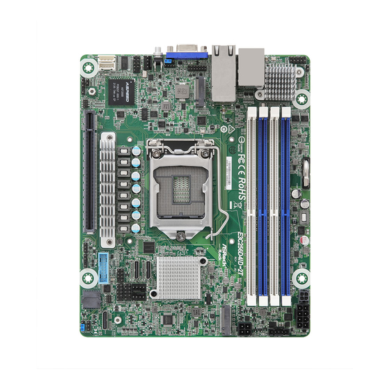
Page 13: Motherboard Layout
E3C256D4ID-2T E3C256D4ID-NL E3C252D4ID-2T 1.4 Motherboard Layout 20.8cm (8.2 in) CMOS Battery ATX4PIN1 DDR4_B1 ATX12V2 NCSI1 Intel DDR4_B2 X710-AT2 (E3C256D4ID-2T / E3C252D4ID-2T only) DDR4_A1 PSU_SMB1 DDR4_A2 USB 3.2 Gen1 T: USB_1 IPMI_LAN B: USB_2 E3C256D4ID-2T E3C256D4ID-NL SATA_PWR1 E3C252D4ID-2T M2_2 LAN1 LAN2... - Page 14 System Fan Connector (FAN2) System Fan Connector (FAN3) Auxiliary Panel Header (ITX_AUX_PANEL1) System Panel Header (PANEL1) OCuLink x4 Connector (OCU3) (E3C256D4ID-2T / E3C256D4ID-NL only) Clear CMOS Pad (CLRMOS1) Thermal Sensor Header (TR1) Security Override Jumper (SEC_OR1) USB 3.2 Gen1 Header (USB3_3_4)
-
Page 15: Onboard Led Indicators
E3C256D4ID-2T E3C256D4ID-NL E3C252D4ID-2T 1.5 Onboard LED Indicators E3C256D4ID-2T Item Status Description SB_PWR1_LED Green STB PWR ready FAN_LED2 FAN2 failed FAN_LED3 FAN3 failed BMC_LED1 Green BMC heartbeat LED FAN_LED1 FAN1 failed... -
Page 16: I/O Panel
1.6 I/O Panel No. Description No. Description 10G LAN RJ-45 Port (LAN2)** USB 3.2 Gen1 Ports (USB3_1_2) (E3C256D4ID-2T / E3C252D4ID-2Tonly) LAN RJ-45 Port (IPMI_LAN)* VGA Port (VGA1) 10G LAN RJ-45 Port (LAN1)** UID Switch (UID1) (E3C256D4ID-2T / E3C252D4ID-2Tonly) LAN Port LED Indications *There are two LEDs on each LAN port. - Page 17 E3C256D4ID-2T E3C256D4ID-NL E3C252D4ID-2T **There are two LEDs on each LAN port. Please refer to the table below for the LAN port LED indications. ACT/LINK LED SPEED LED LAN Port LAN Port LED Indications Activity / Link LED Speed LED Status...
-
Page 18: Block Diagram
1.7 Block Diagram E3C256D4ID-2T Channel A INTEL DDR4 UDIMM PCI-E X16 SLOT 7 Max to 3200 Processor M.2_1 PCI-E Gen4 BUS LGA-1200 Pin Socket DDR4 UDIMM Channel B Max to 3200 HSIO 18-21 SATA 3 / PCIE 6Gb/s Oculink 1 USB3.2 Gen1... - Page 19 E3C256D4ID-2T E3C256D4ID-NL E3C252D4ID-2T E3C256D4ID-NL Channel A INTEL DDR4 UDIMM PCI-E X16 SLOT 7 Max to 3200 Processor M.2_1 PCI-E Gen4 BUS LGA-1200 Pin Socket DDR4 UDIMM Channel B Max to 3200 HSIO 18-21 SATA 3 / PCIE 6Gb/s Oculink 1 USB3.2 Gen1...
- Page 20 E3C252D4ID-2T Channel A INTEL DDR4 UDIMM PCI-E X16 SLOT 7 Max to 3200 Processor M.2_1 PCI-E Gen4 BUS DDR4 UDIMM LGA-1200 Pin Socket Channel B Max to 3200 HSIO 18-21 Oculink 1 USB3.2 Gen1 USB3.2 Gen1 5 Gb/s HSIO 0-1 2 rear ports Type A HSIO 22-25 Oculink 2...
-
Page 21: Chapter 2 Installation
E3C256D4ID-2T E3C256D4ID-NL E3C252D4ID-2T Chapter 2 Installation This is a deep mini ITX form factor (6.7'' x 8.2'', 17.02 cm x 20.82 cm) motherboard. Before you install the motherboard, study the configuration of your chassis to ensure that the motherboard fits into it. -
Page 22: Installing The Cpu
2.3 Installing the CPU 1. Before you insert the CPU into the socket, please check if the PnP cap is on the socket, if the CPU surface is unclean, or if there are any bent pins in the socket. Do not force to insert the CPU into the socket if above situation is found. - Page 23 E3C256D4ID-2T E3C256D4ID-NL E3C252D4ID-2T Please save and replace the cover if the processor is removed. The cover must be placed if you wish to return the motherboard for after service.
-
Page 24: Installing The Heatsink
2.4 Installing the Heatsink... -
Page 25: Installation Of Memory Modules (Dimm)
E3C256D4ID-2T E3C256D4ID-NL E3C252D4ID-2T 2.5 Installation of Memory Modules (DIMM) This motherboard provides four 288-pin DDR4 (Double Data Rate 4) DIMM slots. 1. It is not allowed to install a DDR, DDR2 or DDR3 memory module into a DDR4 slot; otherwise, this motherboard and DIMM may be damaged. -
Page 26: Expansion Slot (Pci Express Slot)
2.6 Expansion Slot (PCI Express Slot) There is a PCI Express slot on this motherboard. PCIE slot: PCIE7 (PCIe 4.0 x16 slot) is used for PCI Express x16 lane width cards. Slot Generation Mechanical Electrical Source PCIE 7 Installing an expansion card Step 1. -
Page 27: Jumper Setup
E3C256D4ID-2T E3C256D4ID-NL E3C252D4ID-2T 2.7 Jumper Setup The illustration shows how jumpers are setup. When the jumper cap is placed on the pins, the jumper is “Short”. If no jumper cap is placed on the pins, the jumper is “Open”. The illustration shows a 3-pin jumper whose pin1 and pin2 are “Short”... -
Page 28: Onboard Headers And Connectors
2.8 Onboard Headers and Connectors Onboard headers and connectors are NOT jumpers. Do NOT place jumper caps over these headers and connectors. Placing jumper caps over the headers and connectors will cause permanent damage to the motherboard. System Panel Header C onnec t t he power sw itch, PLED+ PLED-... - Page 29 E3C256D4ID-2T E3C256D4ID-NL E3C252D4ID-2T Micro-Fit Power The motherboard provides ATX_PG Connector one Micro-Fit power/signal PSON# +5VSB (4-pin ATX4PIN1 connector which is a required input for ATX power source. (ATX 24pin-to-4pin) (see p.6, No. 2) When using ATX power, it is necessary to use a 24pin-to-...
- Page 30 ATX 12V Power The motherboard provides one Connector 8-pin 12V power connector (8-pin ATX12V2) which is a required input for (see p.6, No. 3) either DC-IN 12V or ATX +12V power source. When using ATX power, it is necessary to use a 24pin-to- 4pin power cable to connect between the 24pin power connector of PSU and the...
- Page 31 (see p.6, No. 19) the connectors. (OCU2) O CU1 (see p.6, No. 20) O CU3 (OCU3) (see p.6, No. 13) (E3C256D4ID-2T / E3C256D4ID-NL only) RRXD1 Serial Port Header This COM header supports a DDTR#1 DDSR#1 (9-pin COM1) serial port module.
- Page 32 Clear CMOS Pad CLRMOS1 allows you to clear (CLRMOS1) the data in CMOS. To clear (see p.6, No. 14) CMOS, take out the CMOS battery and short the Clear CMOS Pad. PSU SMBus PSU SMBus monitors the SMBCLK SMBDATA (PSU_SMB1) status of the power supply, fan ALERT (see p.6, No.
-
Page 33: Atx Psu / Dc-In Power Connections
E3C256D4ID-2T E3C256D4ID-NL E3C252D4ID-2T 2.9 ATX PSU / DC-IN Power Connections This motherboard supports both +12V DC and ATX power input. Please refer to the table below for the required connections between the motherboard and the power supply. Connector DC-IN ATX PSU... -
Page 34: Unit Identification Purpose Led/Switch
2.10 Unit Identification purpose LED/Switch With the UID button, You are able to locate the server you’re working on from behind a rack of servers. Unit Identification When the UID button on the purpose LED/Switch front or rear panel is pressed, (UID1) the front/rear UID blue LED indicator will be turned on. -
Page 35: Dual Lan And Teaming Operation Guide
E3C256D4ID-2T E3C256D4ID-NL E3C252D4ID-2T 2.12 Dual LAN and Teaming Operation Guide (E3C256D4ID-2T / E3C252D4ID-2Tonly) Dual LAN with Teaming enabled on this motherboard allows two single connections to act as one single connection for twice the transmission bandwidth, making data transmission more effective and improving the quality of transmission of distant images. - Page 36 2.13 M.2 SSD Module Installation Guide (M2_1/M2_2) The Hyper M.2 Socket (M2_1, Key M) supports a type 2280 PCI Express module up to Gen4 x4 (64 Gb/s). The Ultra M.2 Socket (M2_2, Key M) supports a type 2280 PCI Express module up to Gen3 x4 (32 Gb/s).
-
Page 37: Chapter 3 Uefi Setup Utility
E3C256D4ID-2T E3C256D4ID-NL E3C252D4ID-2T Chapter 3 UEFI Setup Utility 3.1 Introduction This section explains how to use the UEFI SETUP UTILITY to configure your system. The UEFI chip on the motherboard stores the UEFI SETUP UTILITY. You may run the UEFI SETUP UTILITY when you start up the computer. -
Page 38: Navigation Keys
3.1.2 Navigation Keys Please check the following table for the function description of each navigation key. Navigation Key(s) Function Description Moves cursor left or right to select Screens Moves cursor up or down to select items + / - To change option for the selected items <Tab>... -
Page 39: Main Screen
E3C256D4ID-2T E3C256D4ID-NL E3C252D4ID-2T 3.2 Main Screen Once you enter the UEFI SETUP UTILITY, the Main screen will appear and display the system overview. The Main screen provides system overview information and allows you to set the system time and date. -
Page 40: Advanced Screen
3.3 Advanced Screen In this section, you may set the configurations for the following items: CPU Configuration, DRAM Configuration, Chipset Configuration, Storage Configuration, NVMe Configura- tion, ACPI Configuration, Super IO Configuration, Serial Port Console Redirection, H/W Monitor, Intel SPS Configuratio, Driver Health, Network Stack Configuration, Tls Auth Configuration, RAM Disk Configuration, iSCSI Configuration and Instant Flash. -
Page 41: Cpu Configuration
E3C256D4ID-2T E3C256D4ID-NL E3C252D4ID-2T 3.3.1 CPU Configuration SGX settings Hyper-Threading (Supported depending on your CPU) Intel Hyper Threading Technology allows multiple threads to run on each core, so that the overall performance on threaded software is improved. Active Processor Cores Select the number of cores to enable in each processor package. - Page 42 Package C State Support Enable CPU, PCIe, Memory, Graphics C State Support for power saving. Intel (VMX) Virtualization Technology When enabled, a VMM can utiliza the addiyional hardware capabilities provided by Vanderpool Technology. VT-d Intel® Virtualization Technology for Directed I/O helps your virtual machine monitor better utilize hardware by improving application compatibility and reliability, and providing additional levels of manageability, security, isolation, and I/O performance.
- Page 43 E3C256D4ID-2T E3C256D4ID-NL E3C252D4ID-2T Enable Intel TXT Support Use this to enable or disable Intel Trusted Execution Technology. CPU Thermal Throttling Enable CPU internal thermal control mechanisms to keep the CPU from overheating.
-
Page 44: Dram Configuration
3.3.2 DRAM Configuration DRAM Frequency If [Auto] is selected, the motherboard will detect the memory module(s) inserted and assign the appropriate frequency automatically. -
Page 45: Chipset Configuration
Use this to enable or disable the Onboard VGA functions. The default value is [Enabled]. Onboard LAN1 and LAN2 (E3C256D4ID-2T / E3C252D4ID-2T only) Use this to enable or disable the Onboard LAN functions. The default value is [Enabled]. Above 4G Decoding Enable or disable above 4G MemoryMappedIO decoding. - Page 46 This option enables or disables the PCI Express Hot Plug feature. OCU2 Mode Selection Swith the OCUlink to PCIE/SATA. OCU3 Mode Selection (E3C256D4ID-2T / E3C256D4ID-NL only) Swith the OCUlink to PCIE/SATA. OCU3 Link Speed (E3C256D4ID-2T / E3C256D4ID-NL only) This allows you to select OCU1 Link Speed. The default value is [Auto].
-
Page 47: Storage Configuration
E3C256D4ID-2T E3C256D4ID-NL E3C252D4ID-2T 3.3.4 Storage Configuration Hard Disk S.M.A.R.T. S.M.A.R.T. stands for Self-Monitoring, Analysis, and Reporting Technology. It is a monitoring system for computer hard disk drives to detect and report on various indicators or reliability. SATA Storage Configuration SATA Controller Use this item to enable or disable SATA Controllers. -
Page 48: Nvme Configuration
3.3.5 NVMe Configuration The NVMe Configuration displays the NVMe controller and Drive information. -
Page 49: Acpi Configuration
E3C256D4ID-2T E3C256D4ID-NL E3C252D4ID-2T 3.3.6 ACPI Configuration PCIE Devices Power On This allows the system to be waked up by a PCIE device and enable wake-on-LAN. Ring-In Power On This allows the system to be waked up by onboard COM port modem Ring-In signals. -
Page 50: Super Io Configuration
3.3.7 Super IO Configuration Serial Port 1 Configuration Use this item to set parameters of COM1. Serial Port Use this item to enable or disable the serial port. Change Settings Use this item to select an optimal setting for Super IO device. SOL Configuration Use this item to set SOL configuration. -
Page 51: Serial Port Console Redirection
E3C256D4ID-2T E3C256D4ID-NL E3C252D4ID-2T 3.3.8 Serial Port Console Redirection COM1 / SOL Console Redirection Use this option to enable or disable Console Redirection. If this item is set to Enabled, you can select a COM Port to be used for Console Redirection. - Page 52 Bits Per Second Use this item to select the serial port transmission speed. The speed used in the host computer and the client computer must be the same. Long or noisy lines may require lower transmission speed. The options include [9600], [19200], [57600] and [115200]. Data Bits Use this item to set the data transmission size.
- Page 53 E3C256D4ID-2T E3C256D4ID-NL E3C252D4ID-2T Out-of-Band Mgmt Port Microsoft Windows Emergency Mangement Services (EMS) allows for remote management of a Windows Server OS through a serial port. Terminal Type EMS Use this item to select the preferred terminal emulation type for out-of-band management.
-
Page 54: H/W Monitor
3.3.9 H/W Monitor In this section, it allows you to monitor the status of the hardware on your system, includ- ing the parameters of the CPU temperature, motherboard temperature, CPU fan speed, chassis fan speed, and the critical voltage. Watch Dog Timer This allows you to enable or disable the Watch Dog Timer. -
Page 55: Intel Sps Configuration
E3C256D4ID-2T E3C256D4ID-NL E3C252D4ID-2T 3.3.10 Intel SPS Configuration SPS screen displays the Intel SPS Configuration information, such as Operational Firmware Version and Firmware State. -
Page 56: Driver Health
3.3.11 Driver Health This page provides health status for the drivers/controllers. Note: The screenshot here is for for your references only. The items on this page vary depending on models and devices you use. -
Page 57: Network Stack Configuration
E3C256D4ID-2T E3C256D4ID-NL E3C252D4ID-2T 3.3.12 Network Stack Configuration Network Stack Use this item to enable or disable UEFI Network Stack. The default value is [Disabled]. When [Enabled] is selected, the following items appear. Ipv4 PXE Support Use this item to enable or disable IPv4 PXE boot support. If disabled, IPv4 PXE boot support will not be available. - Page 58 keys to set the value. Media detect count Number of times the presence of media will be checked. Use either +/- or numeric keys to set the value.
-
Page 59: Tls Auth Configuration
E3C256D4ID-2T E3C256D4ID-NL E3C252D4ID-2T 3.3.13 Tls Auth Configuration Server CA Configuration Press <Enter> to configure Server CA. Client Cert Configuration Press <Enter> to configure Client Cert. -
Page 60: Ram Disk Configuration
3.3.14 RAM Disk Configuration Disk Memory Type Specifies type of memory to use from available memory pool in system to create a disk. Create raw Create a raw RAM disk. Create from file Create a RAM disk from a given file. Remove selected RAM disk(s). -
Page 61: Iscsi Configuration
E3C256D4ID-2T E3C256D4ID-NL E3C252D4ID-2T 3.3.15 iSCSI Configuration Attempt Priority Change this priority using +/- keys. Use arrow keys to selct the attempt then press +/- to move the attempt up/down in the attempt odder list. Host iSCSI Configuration Use this to configure iSCSI settings. -
Page 62: Instant Flash
3.3.16 Instant Flash Instant Flash is a UEFI flash utility embedded in Flash ROM. This convenient UEFI update tool allows you to update system UEFI without entering operating systems ® first like MS-DOS or Windows . Just save the new UEFI file to your USB flash drive, floppy disk or hard drive and launch this tool, then you can update your UEFI only in a few clicks without preparing an additional floppy diskette or other compli- cated flash utility. -
Page 63: Server Mgmt
E3C256D4ID-2T E3C256D4ID-NL E3C252D4ID-2T 3.4 Server Mgmt Wait For BMC Wait For BMC response for specified time out. BMC starts at the same time when BIOS starts during AC power ON. It takes around 90 seconds to initialize Host to BMC interfaces. -
Page 64: Bmc Network Configuration
3.4.1 BMC Network Configuration BMC Out of band Access Use this item to enable or disable BMC Out of band Access. Manual Setting IPMI LAN If [No] is selected, the IP address is assigned by DHCP. If you prefer using a static IP address, toggle to [Yes], and the changes take effect after the system reboots. - Page 65 E3C256D4ID-2T E3C256D4ID-NL E3C252D4ID-2T The default login information for the IPMI web interface is: Username: admin Password: admin For more instructions on how to set up remote control environment and use the IPMI man- agement platform, please refer to the IPMI Configuration User Guide or go to the Support website at: http://www.asrockrack.com/support/faq.asp...
-
Page 66: System Event Log
3.4.2 System Event Log SEL Components Change this to enable ro disable event logging for error/progress codes during boot. Erase SEL Use this to choose options for earsing SEL. When SEL is Full Use this to choose options for reactions to a full SEL. Log EFI Status Codes Use this item to disable the logging of EFI Status Codes or log only error code or only progress code or both. -
Page 67: Bmc Self Test Log
E3C256D4ID-2T E3C256D4ID-NL E3C252D4ID-2T 3.4.3 Bmc self test log Erase Log Use this to choose options for earsing Log. When Log is Full Use this to select the action to be taken when log is full. -
Page 68: Bmc Tools
3.4.4 BMC Tools Load BMC Default Settings Use this item to Load BMC Default Settings KCS Control Select this KCS interface state after POST end. If [Enabled] us selected, the BMC will remain KCS interface after POST stage. If [Disabled] is selected, the BMC will disable KCS interface after POST stage... -
Page 69: View Fru Information
E3C256D4ID-2T E3C256D4ID-NL E3C252D4ID-2T 3.4.5 View FRU Information This page displays the FRU Information, such as Manufacturer, Product Name, Version, System Serial Number of the system, board and chassis. -
Page 70: Security
3.5 Security In this section, you may set or change the supervisor/user password for the system. For the user password, you may also clear it. Supervisor Password Set or change the password for the administrator account. Only the administrator has authority to change the settings in the UEFI Setup Utility. Leave it blank and press enter to remove the password. -
Page 71: Key Management
E3C256D4ID-2T E3C256D4ID-NL E3C252D4ID-2T 3.5.1 Key Management In this section, expert users can modify Secure Boot Policy variables without full authenti- cation. Factory Key Provision Install factory default Secure Boot keys after the platform reset and while the System is in Setup mode. - Page 72 Remove 'UEFI CA' from DB Device Guard ready system must not list ‘Microsoft UEFI CA’ Certificate in Autho- rized Signature database (db). Restore DB defaults Restore DB variable to factory defaults. Platform Key(PK) Enroll Factory Defaults or load certificates from a file: 1.
- Page 73 E3C256D4ID-2T E3C256D4ID-NL E3C252D4ID-2T 1. Public Key Certificate in: a) EFI_SIGNATURE_LIST b) EFI_CERT_X509 (DER) c) EFI_CERT_RSA2048 (bin) d) EFI_CERT_SHAXXX 2. Authenticated UEFI Variable 3. EFI PE/COFF Image(SHA256) Key Source: Factory, External, Mixed Forbidden Signatures Enroll Factory Defaults or load certificates from a file: 1.
- Page 74 OsRecovery Signatures Enroll Factory Defaults or load certificates from a file: 1. Public Key Certificate in: a) EFI_SIGNATURE_LIST b) EFI_CERT_X509 (DER) c) EFI_CERT_RSA2048 (bin) d) EFI_CERT_SHAXXX 2. Authenticated UEFI Variable 3. EFI PE/COFF Image(SHA256) Key Source: Factory, External, Mixed...
-
Page 75: Boot Screen
E3C256D4ID-2T E3C256D4ID-NL E3C252D4ID-2T 3.6 Boot Screen In this section, it will display the available devices on your system for you to configure the boot settings and the boot priority. Boot Option #1 Use this item to set the system boot order. - Page 76 UEFI NVME Drive BBS Priorities Specifies the Boot Device Priority sequence from available UEFI NVME Drives. UEFI NEYWORK Drive BBS Priorities Specifies the Boot Device Priority sequence from available UEFI NETWORK Drives. UEFI Application Boot Priorities Specifies the Boot Device Priority sequence from available UEFI Application. Setup Prompt Timeout This shows the number of seconds to wait for setup activation key.
-
Page 77: Csm Parameters
E3C256D4ID-2T E3C256D4ID-NL E3C252D4ID-2T 3.6.1 CSM Parameters Enable to launch the Compatibility Support Module. Please do not disable unless you’re running a WHCK test. If you are using Windows 8.1 64-bit and all of your devices support UEFI, you may also disable CSM for faster boot speed. -
Page 78: Event Logs
3.7 Event Logs Change Smbios Event Log Settings This allows you to configure the Smbios Event Log Settings. When entering the item, you will see the followings: Smbios Event Log Use this item to enable or disable all features of the SMBIOS Event Logging during system boot. -
Page 79: Exit Screen
E3C256D4ID-2T E3C256D4ID-NL E3C252D4ID-2T 3.8 Exit Screen Save Changes and Exit When you select this option, the following message “Save configuration changes and exit setup?” will pop-out. Press <F10> key or select [Yes] to save the changes and exit the UEFI SETUP UTILITY. -
Page 80: Chapter 4 Software Support
4.3 Contact Information If you need to contact ASRock Rack or want to know more about ASRock Rack, welcome to visit ASRock Rack’s website at http://www.ASRockRack.com; or you may contact your... -
Page 81: Chapter 5 Troubleshooting
E3C256D4ID-2T E3C256D4ID-NL E3C252D4ID-2T Chapter 5 Troubleshooting 5.1 Troubleshooting Procedures Follow the procedures below to troubleshoot your system. Always unplug the power cord before adding, removing or changing any hardware com- ponents. Failure to do so may cause physical injuries to you and damages to motherboard components. - Page 82 1. Verify if the battery on the motherboard provides ~3VDC. Install a new battery if it does not. 2. Confirm whether your power supply provides adaquate and stable power. Other problems... 1. Try searching keywords related to your problem on ASRock Rack’s FAQ page: http://www.asrockrack.com/support...
-
Page 83: Technical Support Procedures
E3C252D4ID-2T 5.2 Technical Support Procedures If you have tried the troubleshooting procedures mentioned above and the problems are still unsolved, please contact ASRock Rack’s technical support with the following information: 1. Your contact information 2. Model name, BIOS version and problem type.
Need help?
Do you have a question about the E3C256D4ID-2T and is the answer not in the manual?
Questions and answers