Sign In
Upload
Download
Table of Contents
Contents
Add to my manuals
Delete from my manuals
Share
URL of this page:
HTML Link:
Bookmark this page
Add
Manual will be automatically added to "My Manuals"
Print this page
×
Bookmark added
×
Added to my manuals
Manuals
Brands
ASROCK Rack Manuals
Motherboard
E3C246D4U
User manual
ASROCK Rack E3C246D4U User Manual
Server / workstation motherboard
Hide thumbs
1
2
3
Table Of Contents
4
5
6
7
8
9
10
11
12
13
14
15
16
17
18
19
20
21
22
23
24
25
26
27
28
29
30
31
32
33
34
35
36
37
38
39
40
41
42
43
44
45
46
47
48
49
50
51
52
53
54
55
56
57
58
59
60
61
62
63
64
65
66
67
68
69
70
71
72
73
74
75
76
77
78
79
80
81
82
83
84
85
86
87
page
of
87
Go
/
87
Contents
Table of Contents
Troubleshooting
Bookmarks
Table of Contents
Table of Contents
Chapter 1 Introduction
Package Contents
Specifications
Unique Features
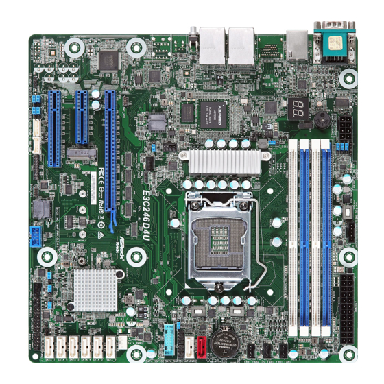
Motherboard Layout
Onboard LED Indicators
I/O Panel
Block Diagram
Chapter 2 Installation
Screw Holes
Pre-Installation Precautions
Installing the CPU
Installing the CPU Fan and Heatsink
Installation of Memory Modules (DIMM)
Expansion Slots (PCI Express Slots)
Jumper Setup
Onboard Headers and Connectors
Dr. Debug
Unit Identification Purpose Led/Switch
Driver Installation Guide
Dua LAN and Teaming Operation Guide
M.2_SSD (NGFF) Module Installation Guide
Chapter 3 UEFI Setup Utility
Introduction
UEFI Menu Bar
Navigation Keys
Main Screen
Advanced Screen
CPU Configuration
DRAM Configuration
Chipset Configuration
Storage Configuration
Nvme Configuration
ACPI Configuration
USB Configuration
Super IO Configuration
Serial Port Console Redirection
H/W Monitor
Intel SPS Configuration
Instant Flash
Server Mgmt
System Event Log
BMC Network Configuration
Security
Key Management
Boot Screen
CSM Parameters
Event Logs
Exit Screen
Chapter 4 Software Support
Install Operating System
Support CD Information
Running the Support CD
Drivers Menu
Utilities Menu
Contact Information
Chapter 5 Troubleshooting
Troubleshooting Procedures
Technical Support Procedures
Returning Merchandise for Service
Advertisement
Quick Links
1
Motherboard Layout
2
Jumper Setup
3
Troubleshooting Procedures
Download this manual
E3C246D4U
E3C242D4U
User Manual
Version 1.0
Published June 2018
Copyright©2018 ASRock Rack INC. All rights reserved.
Table of
Contents
Previous
Page
Next
Page
1
2
3
4
5
Advertisement
Table of Contents
Need help?
Do you have a question about the E3C246D4U and is the answer not in the manual?
Ask a question
Questions and answers
Related Manuals for ASROCK Rack E3C246D4U
Motherboard ASROCK Rack E3C236D4I-44E85 User Manual
(79 pages)
Motherboard ASROCK Rack E3C232D2I Quick Installation Manual
(2 pages)
Motherboard ASROCK Rack E3C236D4HM-2L+ Quick Installation Manual
(2 pages)
Motherboard ASROCK Rack E3C246D2I User Manual
(83 pages)
Motherboard ASROCK Rack E3C242D4U User Manual
Server / workstation motherboard (87 pages)
Motherboard ASROCK Rack E3C246D4I-2T User Manual
Server/workstation motherboards (76 pages)
Motherboard ASROCK Rack E3C256D4U-2L2T User Manual
Server/workstation (90 pages)
Motherboard ASROCK Rack E3C256D4ID-2T User Manual
(83 pages)
Motherboard ASROCK Rack EP2C622D16NM User Manual
Server / workstation (87 pages)
Motherboard ASROCK Rack EP2C621D12 WS User Manual
Stable and reliable solution, server/workstation motherboard (99 pages)
Motherboard ASROCK Rack EPC621D4I-2M User Manual
(81 pages)
Motherboard ASROCK Rack EPYCD8-2T User Manual
(83 pages)
Motherboard ASROCK Rack EPYCD8/R32 User Manual
(83 pages)
Motherboard ASROCK Rack EP2C621D8 User Manual
Server/workstation motherboard (86 pages)
Motherboard ASROCK Rack EPYC3451D4I2-2T User Manual
(70 pages)
Motherboard ASROCK Rack EP2C612D16C-4L User Manual
(94 pages)
This manual is also suitable for:
E3c242d4u
C246m ws
Table of Contents
Print
Rename the bookmark
Delete bookmark?
Delete from my manuals?
Login
Sign In
OR
Sign in with Facebook
Sign in with Google
Upload manual
Upload from disk
Upload from URL


Need help?
Do you have a question about the E3C246D4U and is the answer not in the manual?
Questions and answers