
Related Manuals for IFM UIT509


Summary of Contents for IFM UIT509
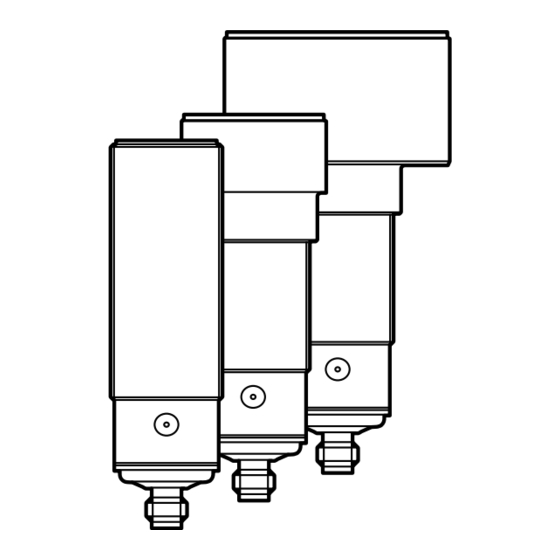
- Page 1 Operating instructions Ultrasonic diffuse-reflection sensor without IO-Link UIT509 UIT512 UIT515...
- Page 2 1 Preliminary note 1.1 Symbols used ► Instructions > Reaction, result […] Designation of keys, buttons or indications → Cross-reference Important note Non-compliance may result in malfunction or interference. Information Supplementary note. 2 Safety instructions • Read this document before setting up the product and keep it during the entire service life.
- Page 3 For units with metal housing (according to UL 508): ► Observe a minimum distance of 12.7 mm between the sensor and non- insulated live parts. For further information please refer to www.ifm.com → General information about installation and operation. 5 Electrical connection ►...
- Page 4 6 Settings The unit and the parameters are set via the teach button (→ 6.1). 6.1 teach button 6.1.1 Start programming mode ► Press the teach button for 2 s...6 s. > Yellow status LEDs 1/2 flash (1 Hz), the unit is in the programming mode. If programming has not been completed successfully, the unit returns to the previous setting.
- Page 5 P1/P2 2 Inverted switching outputs Inverted switching outputs P1/P2 1: output response B: blind zone 2: distance to the object P: taught position 3: OUT1 (switching output) T: teach button 4: OUT2 (switching output) Technical data and further information at www.ifm.com...
Need help?
Do you have a question about the UIT509 and is the answer not in the manual?
Questions and answers