Advertisement
Terminated Contact
1. INTRODUCTION
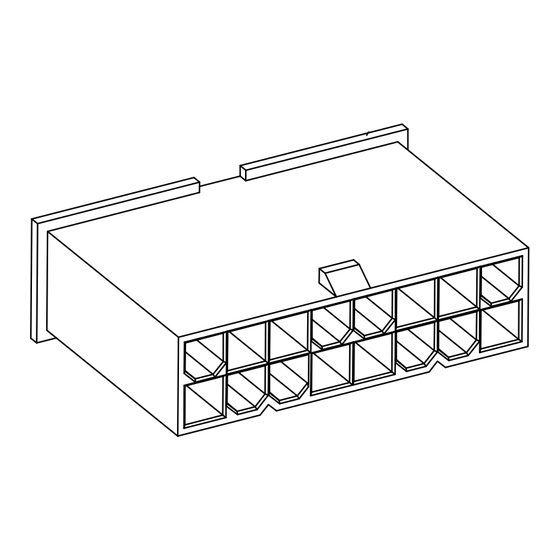
This instruction sheet covers assembling a terminated
contact, housing and TPA as represented in Figure 1
and extracting the contacts from the housing.
Reasons for reissue of this instruction sheet are
provided in Section 6, REVISION SUMMARY.
NOTE
i
NOTE
Dimensions in these instructions are in metric units [with
inches in brackets]. Figures and illustrations are for
reference only and are not drawn to scale.
2. DESCRIPTION
All VAL-U-LOK pin and socket contacts have two
flexible latches that lock into their respective housings
when fully inserted. The TPA-compatible contacts
have special features on their insulation barrels that
work in conjunction with the TPA device to ensure full
contact insertion. See Figure 2A.
The plug and receptacle housings are available in 2
through 24 positions which are arranged into 2 rows.
The TPA devices are available in 1 through 12
positions, single row, so 2 TPA devices are required
for each housing. The TPA is designed to be installed
into the housing to ensure all contacts are fully
inserted and will not back out during mating. When
fully installed, the locking latches of the TPA snap onto
raised ledges around the perimeter of the housing.
See Figure 3B.
3. ASSEMBLY
1. Ensure that the contact is properly terminated to
the wire according to the requirements provided in
Application Specification 114-13172. Check that the
flexible latches are not damaged or distorted from
their original form as shown in Figure 2A.
©2013 Tyco Electronics Corporation, a TE Connectivity Ltd. company
All Rights Reserved
*Trademark
TE Connectivity, TE connectivity (logo), and TE (logo) are trademarks. Other logos, product and/or company names may be trademarks of their respective owners.
VAL-U-LOK* Connector System
with Terminal Position Assurance
Housing
Figure 1
2A
2B
TOOLING ASSISTANCE CENTER 1-800-722-1111
PRODUCT INFORMATION 1-800-522-6752
2. Insert the terminated contact into its respective
housing as follows:
a. Grasp the contact directly behind the
insulation barrel. Align the contact with a contact
cavity in the housing at the wire entry end as
shown in Figure 2A. Make sure that the contact is
perfectly aligned (not angled or rotated) to the
contact cavity. See Figure 2B.
Special Features on
Insulation Barrel
Flexible
Latches
Contact Perfectly Aligned
Angled or Rotated Entry Not Acceptable
Figure 2
This controlled document is subject to change.
For latest revision and Regional Customer Service,
visit our website at www.te.com
Instruction Sheet
408-32113
18 OCT 13 Rev A
TPA
1 of 2
Advertisement
Table of Contents

Subscribe to Our Youtube Channel
Related Manuals for TE Connectivity VAL-U-LOK 3-1586040-6


Summary of Contents for TE Connectivity VAL-U-LOK 3-1586040-6
- Page 1 All Rights Reserved PRODUCT INFORMATION 1-800-522-6752 For latest revision and Regional Customer Service, *Trademark visit our website at www.te.com TE Connectivity, TE connectivity (logo), and TE (logo) are trademarks. Other logos, product and/or company names may be trademarks of their respective owners.
- Page 2 408-32113 CAUTION NOTE NOTE Never insert the contact upside down; otherwise, the TPAs with more than 5 positions have 4 locking latches. locking latches could depress and lodge into the cavity TPAs with 5 positions or less have only 2 locking in an unseated position or become compressed so that latches.
Need help?
Do you have a question about the VAL-U-LOK 3-1586040-6 and is the answer not in the manual?
Questions and answers