Table of Contents
Advertisement
Quick Links
Instructions and Parts List
AccuGlide
HST 3-Inch
HST 3-Inch
Taping Heads
Type 29100
3M Masking and Packaging Systems Division
3M Center Bldg. 220-8W-01
St. Paul, MN 55144-1000
TM
(Upper)
(Lower)
Important
Safeguards
Turn to page four
for operating
safety information.
Important
It is recommended you
immediately order the
spare parts listed on
page 21. These parts
are expected to wear
through normal use,
and should be kept on
hand to minimize
production delays.
"AccuGlide" is a Trademark of 3M,
St. Paul, MN 55144-1000
Litho in U.S.A
© 3M 1996 44-0009-1832-4(B26.025))
Advertisement
Table of Contents

Subscribe to Our Youtube Channel
Related Manuals for 3M AccuGlide HST Upper


Summary of Contents for 3M AccuGlide HST Upper
- Page 1 "AccuGlide" is a Trademark of 3M, St. Paul, MN 55144-1000 3M Masking and Packaging Systems Division Litho in U.S.A 3M Center Bldg. 220-8W-01 St.
- Page 2 Minimum billing on parts orders will be $25.00. Replacement part prices available on request. $10.00 restocking charge per invoice on returned parts. Note : Outside the U.S., contact the local 3M subsidiary for parts ordering information. "3M-Matic", "AccuGlide" and “Scotch” are trademarks of 3M Packaging Systems Division 3M, St.
- Page 3 Replacement Parts And Service Information To Our Customers: This is the 3M-Matic™/AccuGlide™/Scotch™ brand equipment you ordered. It has been set up and tested in the factory with "Scotch" brand tapes. If any problems occur when operating this equipment, and you desire a service call, or phone consultation, call, write or Fax the appropriate number listed below.
-
Page 4: Table Of Contents
Instruction Manual HST 3-Inch Taping Head (Upper) HST 3-Inch Taping Head (Lower) Type 29100 Table of Content Page Taping Head Contents ........................Equipment Warranty and Limited Remedy ..................Description ............................Important Safeguards ........................Specifications ............................ Installation ............................6 - 7 Special Use Set-Up HST Upper Taping Head –... -
Page 5: Taping Head Contents
Taping Head Contents HST 3-Inch Taping Head (Upper) Consists Of: Qty. Part Name Taping Head Assembly Tape Drum and Bracket Assembly Blade – 3.33 inch [77.5 mm] Lg. (Spare) Compression Spring (Upper taping head for side mounting - see page 9) Mounting Stud, Alternate (For use with optional HST mounting frame –... -
Page 6: Equipment Warranty And Limited Remedy
3M. A part will be presumed to have become defective after the warranty period unless the part is received or 3M is notified of the problem no later than five (5) calendar days after the warranty period. If 3M is unable to repair or replace the part within a reasonable time, then 3M, at its option, will replace the equipment or refund the purchase price. -
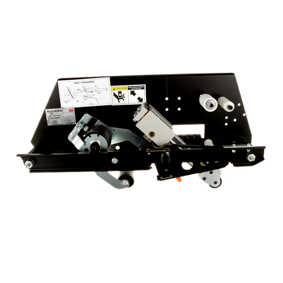
Page 7: Description
AccuGlide HST 3-Inch Taping Heads (Upper and Lower), Type 29100 Description The AccuGlide HST 3-Inch Taping Heads (Upper and Lower) were designed to replace taping, gluing, and stapling heads in existing case sealing machines. These high-speed heavy duty heads apply a “C” clip of Scotch brand pressure-sensitive film box sealing tape to the top and/or bottom center seam of regular slotted containers at speeds up to 150 ft/min [45.7 m/min]. -
Page 8: Important Safeguards
Important Safeguards Both the upper and lower taping heads have important safeguards listed below, every person who operates and/or maintains the heads should be familiar with these safeguards. The “Warning - Sharp Knife” label is used on each head to warn operators and service personnel of the extremely sharp blades used to cut the tape at the end of the box sealing operation. -
Page 9: Specifications
Specifications These specifications apply to all HST 3-Inch Upper and Lower taping heads except where noted. Tape: For use with Scotch brand pressure-sensitive film box sealing tapes. Tape Width: 2 inches [50 mm] minimum to 3 inches [76.2 mm] maximum. Tape Roll Diameter: Position A (Figure 2-1) –... -
Page 10: Installation
Installation Figure 2-1 – Taping Head Assemblies – Typical Mounting Dimensions... - Page 11 If this is not possible, contact 3M for assistance or suggested modifications that will provide adequate operating clearance to the taping head assembly.
- Page 12 THIS PAGE IS BLANK...
-
Page 13: Special Use Set-Up
Special Use Set-Up Instructions HST 3-Inch Upper Taping Head - Compression Spring Refer to Figure 3-1 WARNING – UPPER TAPING HEAD UTILIZES AN EXTREMELY SHARP KNIFE BLADE LOCATED UNDER THE ORANGE BLADE GUARD WHICH HAS THE “WARNING – SHARP KNIFE” LABEL. USE CARE WHEN WORKING NEAR BLADE. -
Page 14: Set-Up Procedure
Set-Up Procedure Figure 4-1 – Tape Threading Diagram – Upper Taping Head Figure 4-2 –Tape Threading Diagram – Lower Taping Head... -
Page 15: Tape Loading
Set-Up Procedure (Continued) Tape Loading The HST 3-Inch taping head accommodates up to 3 inch [72 mm] wide tape rolls. To apply 1-1/2 inch [36 mm], 1-3/4 inch [42 mm] or 2 inch [50 mm] wide tapes, refer to "Adjustments" section for set-up information. WARNING BOTH THE UPPER AND LOWER TAPING HEADS UTILIZE EXTREMELY SHARP KNIFE BLADES WHICH ARE LOCATED UNDER THE ORANGE BLADE GUARD WITH THE... -
Page 16: Adjustments
Adjustments WARNING – NEVER ATTEMPT TO WORK ON THE TAPING HEADS WHEN THE BOX DRIVE SYSTEM IS RUNNING. INJURY TO PERSONNEL OR EQUIPMENT DAMAGE CAN POTENTIALLY RESULT. Tape Web Alignment Refer to Figure 5-1 The HST 3-Inch tape drum assembly is pre-set to accommodate 3 inch [72 mm] wide tape. -
Page 17: Buffing Roller Spring Tension
Adjustments (Continued) Buffing Roller Spring Tension Refer to Figures 5-3 and 5-4 WARNING – USE CARE WHEN WORKING ON BUFFING ROLLER ASSEMBLY AS SPRING IS UNDER TENSION. IF CARE IS NOT TAKEN PERSONNEL INJURY COULD RESULT. The buffing roller spring controls the buffing roller pressure on the box and returns the assembly to the reset position. -
Page 18: Tape Application Leg Length
Adjustments (Continued) Tape Application Leg Length Refer to Figure 5-5 The conveyor speed, at which the product moves through the taping heads, affect the leading and trailing tape application leg length. For best tape application performance, the taping heads should maintain tape leg lengths of 2 3/4 inch ±... -
Page 19: One-Way Tension Roller Assembly
Adjustments (Continued) One-Way Tension Roller Assembly Refer to Figure 5-7 The one-way tension roller is factory set. When replacing this assembly, the roller must have 1 lb. [0.5 kg] tangential force when turning. To Set Tension Wrap a cord or small strap (non-adhesive) 4-6 turns around the tension roller. - Page 20 THIS PAGE IS BLANK...
-
Page 21: Maintenance
Maintenance The taping heads have been designed for long, trouble free service. The taping head will perform best when it receives routine maintenance and cleaning. Taping head components that fail or wear excessively should be promptly repaired or replaced to prevent damage to other portions of the head or to the product. WARNING –... - Page 22 Maintenance (Continued) Figure 6-1 – Blade Replacement...
-
Page 23: Blade Replacement
Maintenance (Continued) WARNING – TURN OFF ELECTRICAL POWER SUPPLY AND DISCONNECT POWER CORD FROM ELECTRICAL SUPPLY BEFORE BEGINNING MAINTENANCE. IF POWER CORD IS NOT DISCONNECTED, SEVER INJURY TO PERSONNEL COULD RESULT. USE CARE WHEN REPLACING BLADES AS BLADES ARE EXTREMELY SHARP. IF CARE IS NOT TAKEN, SEVERE INJURY TO PERSONNEL COULD RESULT. -
Page 24: Lubrication
Maintenance (Continued) Lubrication Refer to Figure 6-2 Like most other equipment, the taping head must be properly lubricated to insure long, trouble free service. Figure 6-2 illustrates points which should be lubricated every 250 hours of operation. Lubricate the rotating and pivoting points noted by the arrows ( ) with SAE #30 non-detergent oil. -
Page 25: Replacement Parts And Service Information
Replacement Parts And Service Information Spare Parts A set of spare parts that will periodically require replacement due to normal wear is supplied with the taping heads. The set includes the following which should be reordered as consumed to keep the taping heads in production: HST 3-Inch Taping Head (Upper and Lower) Qty. - Page 26 THIS PAGE IS BLANK...
- Page 27 Refer to first page of this instruction manual for parts ordering address and/or phone/fax number. IMPORTANT – Not all the parts listed are normally stocked items. Some parts or assemblies shown are available only on a special order basis. Contact 3M/Tape Dispenser Parts to confirm item availability.
- Page 28 THIS PAGE IS BLANK...
- Page 29 HST 3-Inch, Type 29100 Taping Head Assemblies...
- Page 30 HST 3-Inch, Type 29100 Figure 7...
- Page 31 Figure 7 – HST, Type 29100 Ref. No. 3M Part No. Description * 78-8079-5167-4 Frame – Taping Head (Upper Head) * 78-8079-5166-6 Frame – Taping Head (Lower Frame) * 78-8079-5170-8 Rail (Upper Head) * 78-8079-5169-0 Rail (Lower Head) 78-8057-5702-4 Pin – Mounting 78-8057-5701-6 Stud –...
- Page 32 HST 3-Inch, Type 29100 Figure 8...
- Page 33 Figure 8 – HST 3-Inch, Type 29100 Ref. No. 3M Part No. Description 78-8062-4209-1 Lever Latch Assembly (Upper Head) 78-8062-4178-8 Lever Latch Assembly (Lower Head) * 26-1009-8993-3 Screw – Cap, Button Hd, Hex Soc, Self Locking, 3/8-16 x 1-1/4 Lg * 70-8000-0247-2 Screw –...
- Page 34 HST 3-Inch, Type 29100 Figure 9...
- Page 35 Figure 9 – HST 3-Inch, Type 29100 Ref. No. 3M Part No. Description 78-8079-5001-5 Cut-Off Bracket Assembly (Upper Head) (Includes items 2-12) 78-8070-1695-7 Cut-Off Bracket Assembly (Lower Head) (Includes items 2-12) 78-8079-5002-3 Frame - Cut-Off Bracket (Upper Head) 78-8070-1696-5 Frame – Cut-Off Bracket (Lower Head) 78-8079-5008-0 Shaft –...
- Page 36 HST 3-Inch, Type 29100 Figure 10...
- Page 37 Figure 10 – HST 3-Inch, Type 29100 Ref. No. 3M Part No. Description * 70-8000-0885-9 Screw – Cap, Soc Hd, 5/16-18 x 3/8 Lg 70-8656-5938-0 Screw – Cap, Soc Hd, 1/4-20 x 1/2 Lg 78-8062-4204-2 Pin – Buffing * 70-8000-5400-2 Screw –...
- Page 38 HST 3-Inch, Type 29100 Figure 11...
- Page 39 Figure 11 – HST 3-Inch, Type 29100 Ref. No. 3M Part No. Description 78-8076-4732-2 Tape Drum/Shaft Assembly – 3 Inch (Includes items 2, 6-10) 78-8076-4731-4 Tape Drum Assembly – 3 Inch (Includes items 3-5) 26-1002-5753-9 Screw – Self Tapping 78-8054-8816-6 Spring –...
Need help?
Do you have a question about the AccuGlide HST Upper and is the answer not in the manual?
Questions and answers