Table of Contents
Advertisement
OP E R AT ING MA NUA L
HE AT & COOL M ODE L
(R E V E R S E CY CLE )
R OOM A IR CON DIT ION E R
W A LL M OU N T E D T Y PE
Indoor U nit
A S Y 10U S A CW
A S Y 12U S A CW
Outdoor U nit
A OY 10U S A C
A OY 12U S A C
K E E P T HIS OPE R AT ION M A N U A L
FOR FU T U R E R E FE R E N CE
FUJITSU GENERAL LIMITED
P/N 9308814036-02
Advertisement
Table of Contents

Related Manuals for Fujitsu ASY10USACW


Summary of Contents for Fujitsu ASY10USACW
- Page 1 A OY 12U S A C K E E P T HIS OPE R AT ION M A N U A L FOR FU T U R E R E FE R E N CE FUJITSU GENERAL LIMITED P/N 9308814036-02...
- Page 2 Fig. 1 Fig. 2 Fig. 3 Fig. 5 Fig. 4 Fig. 6 Fig. 8 Fig. 7...
-
Page 3: Table Of Contents
CONTENTS SAFETY PRECAUTIONS ........En-1 ADJUSTING THE DIRECTION OF FEATURES AND FUNCTIONS ......En-2 AIR CIRCULATION ..........En-9 NAME OF PARTS ..........En-3 SWING OPERATION ......... En-10 PREPARATION ............ En-4 MANUAL AUTO OPERATION ......En-10 OPERATION ............En-5 CLEANING AND CARE ........En-11 TIMER OPERATION .......... -
Page 4: Features And Functions
FEATURES AND FUNCTIONS AUTOMATIC OPERATION REMOVABLE INTAKE GRILLE Merely press the START/STOP button, and the unit will be- The indoor unit’s INTAKE GRILLE can be removed for easy gin automatic operation in either the Heating, Cooling, Dry, cleaning and maintenance. or Monitor modes as appropriate, in accordance with the thermostat setting and the actual temperature of the room. -
Page 5: Name Of Parts
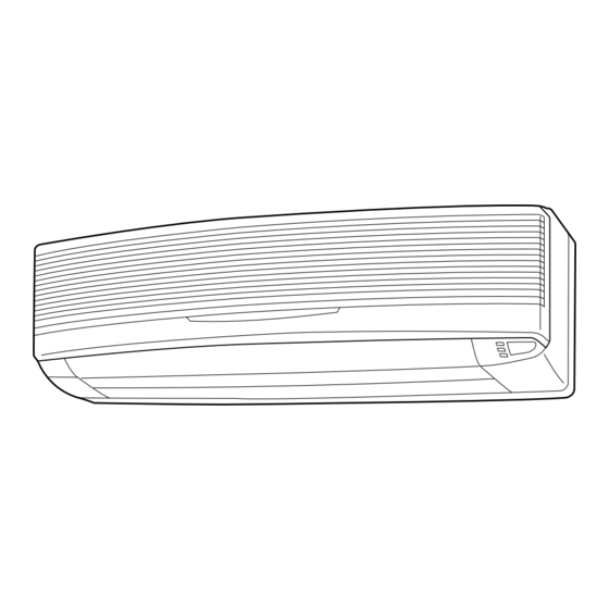
NAME OF PARTS Fig. 1 Indoor Unit Fig. 6 Remote Control Unit 1 Operating Control Panel (Fig. 2) L SLEEP button 2 POWER Switch M MASTER CONTROL button 3 MANUAL AUTO button N SET TEMP./SET TIME buttons ( O Signal Transmitter 4 Remote Control Signal Receiver P TIMER button 5 Indicator Lamps (Fig. -
Page 6: Preparation
PREPARATION CAUTION! Turn on the Power G Take care to prevent infants from accidentally swallowing batteries. Connect the Power Supply Plug (Fig. 1 E) to an electri- G When not using the remote control unit cal outlet; in the case of a direct line connection, turn for an extended period, remove the batteries to avoid possible leakage and on the circuit breaker. -
Page 7: Operation
OPERATION To Select Mode Operation Press the START/STOP button (Fig.6 R). The indoor unit’s OPERATION indicator lamp (red) (Fig. 3 6) will light. The air conditioner will start operating. Press the MASTER CONTROL button (Fig.6 M) to se- lect the desired mode. Each time the button is pressed, the mode will change in the following order. - Page 8 To Stop Operation Press the START/STOP button. The OPERATION Indicator Lamp (red) (Fig. 3 6) will go out. About Mode Operation G Depending on the room temperature at the time operation begins, the AUTO: During Heating mode: operating mode will be switched automatically as shown in the Set the thermostat to a temperature set- accompanying table.
-
Page 9: Timer Operation
TIMER OPERATION Before using the timer function, be sure that the Remote Control Unit is set to the correct current time (See page 4). To Use the ON timer or OFF timer To Cancel the Timer Press the START/STOP button (Fig. 6 R) Use the TIMER button to select “TIMER (if the unit is already operating, proceed to step 2). -
Page 10: Sleep Timer Operation
SLEEP TIMER OPERATION Unlike other timer functions, the SLEEP timer is used to set the length of time until air conditioner operate is stopped. To Use the SLEEP timer To Cancel the Timer: While the air conditioner is operating or stopped, press the Use the TIMER button to select “TIMER SLEEP button (Fig. -
Page 11: Adjusting The Direction Of Air Circulation
ADJUSTING THE DIRECTION OF AIR CIRCULATION Vertical (up-down) direction of airflow is adjusted by pressing the Remote Control Unit’s AIR FLOW DIRECTION button. Hori- zontal (right-left) airflow direction is adjusted manually, by moving the Air Flow Direction Louvers. Whenever making horizontal airflow adjustments, start air conditioner operation and be sure that the vertical air direction louvers and the power diffuser (Fig. -
Page 12: Swing Operation
SWING OPERATION Begin air conditioner operation before performing this procedure. To select SWING Operation Press the SWING LOUVER button (Fig. 6 T). The SWING indicator lamp (orange) (Fig. 3 8) will light. In this mode, the Air Flow Direction Louvers will swing automatically to direct the air flow both up and down. -
Page 13: Cleaning And Care
CLEANING AND CARE G Before cleaning the air conditioner, be sure to turn it off and disconnect the Power Supply Cord. CAUTION! G Be sure the Intake Grille (Fig. 1 9) is installed securely. G When removing and replacing the air filters, be sure not to touch the heat exchanger, as per- sonal injury may result. - Page 14 TROUBLESHOOTING In the event of a malfunction (burning smell, etc.), immediately stop operation, disconnect the WARNING! Power Supply Plug, and consult authorized service personnel. Merely turning off the unit’s power switch will not completely disconnect the unit from the power source.
-
Page 15: Troubleshooting
TROUBLESHOOTING Symptom Items to check See Page G Is the Power Supply Plug disconnected its outlet? CHECK ONCE Doesn’t operate at all: MORE G Has there been a power failure? — G Has a fuse blown out, or a circuit breaker been tripped? G Is the main POWER Switch set to the OFF position? G Is the timer operating? 7 - 8... - Page 16 OPERATING TIPS Temperature and Humidity Range Cooling Mode Dry Mode Heating Mode About 21-43 °C About 21-43 °C About –5-24 °C Outdoor temperature About 18-32 °C About 18-32 °C About 27 °C or less Indoor temperature G If the air conditioner is used under higher temperature conditioner than those listed, the built-in protection circuit may operate to prevent internal circuit damage.
Need help?
Do you have a question about the ASY10USACW and is the answer not in the manual?
Questions and answers