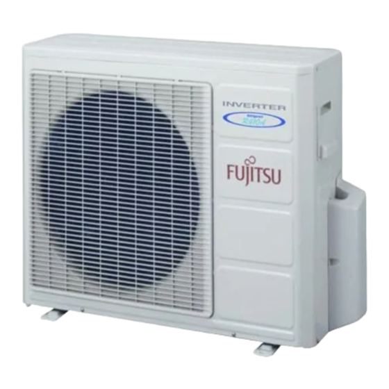
Fujitsu ASY7LMACW Service Manual
Inverter multi
air conditioner
wall mounted type
Hide thumbs
Also See for ASY7LMACW:
- Service manual (21 pages) ,
- Service manual (23 pages) ,
- Service manual (23 pages)
Advertisement
Table of Contents
- 1 Table of Contents
- 2 Wall Mounted
- 3 Specifications
- 4 Outline and Dimensions
- 5 Refrigerant System Diagram
- 6 Circuit Diagram
- 7 Indoor Pcb Circuit Diagram
- 8 Outdoor Pcb Circuit Diagram
- 9 Error Contents
- 10 Disassembly Illustration
- 11 Parts List
- 12 Indoor Unit Accessories
- 13 Standard Accessories
- Download this manual
See also:
Service Manual
INVERTER MULTI
AIR CONDITIONER
WALL MOUNTED
Models
Indoor unit
ASY7LMACW
ASY9LMACW
ASY12LMACW
CONTENTS
SPECIFICATIONS . . . . . . . . . . . . . . . . . . . .
OUTLINE AND DIMENSIONS . . . . . . . . . .
REFRIGERANT SYSTEM DIAGRAM . . . .
CIRCUIT DIAGRAM . . . . . . . . . . . . . . . . . .
INDOOR PCB CIRCUIT DIAGRAM . . . . . . .
OUTDOOR PCB CIRCUIT DIAGRAM . . . . .
ERROR CONTENTS . . . . . . . . . . . . . . . . . .
DISASSEMBLY ILLUSTRATION . . . . . . . 11
PARTS LIST . . . . . . . . . . . . . . . . . . . . . . . 13
STANDARD ACCESSORIES . . . . . . . . . . . 15
type
Outdoor unit
AOY18LMAK2
1
2
3
4
6
7
8
Advertisement
Table of Contents

Subscribe to Our Youtube Channel
Summary of Contents for Fujitsu ASY7LMACW
-
Page 1: Table Of Contents
AIR CONDITIONER WALL MOUNTED type Models Indoor unit Outdoor unit ASY7LMACW ASY9LMACW AOY18LMAK2 ASY12LMACW CONTENTS SPECIFICATIONS ....OUTLINE AND DIMENSIONS .. -
Page 2: Specifications
SPECIFICATIONS TYPE COOL & HEAT ASY7LMACW ASY9LMACW ASY12LMACW INDOOR UNIT AOY18LMAK2 OUTDOOR UNIT ELECTRICAL DATA ( INDOOR UNIT ) COOLING CAPACITY (kW) HEATING CAPACITY (kW) MOISTURE REMOVAL ( /hr) AIR CIRCULATION-Hi /hr) ELECTRICAL DATA ( OUTDOOR UNIT ) POWER SOURCE... -
Page 3: Outline And Dimensions
OUTLINE AND DIMENSIONS Unit : mm INDOOR UNIT Models : ASY7LMACW ASY9LMACW ASY12LMACW OUTDOOR UNIT Model : AOY18LMAK2 Air flow Bottom 2005.06.10... -
Page 4: Refrigerant System Diagram
REFRIGERANT SYSTEM DIAGRAM A Unit heat exchanger (Outdoor) strainer heat exchanger (Indoor) receiver tank strainer B Unit 2-way electric valve expansion valve 4-way valve 3-way valve COMP compresser HEAT accumulator COOL 2005.08.19... -
Page 5: Circuit Diagram
CIRCUIT DIAGRAM INDOOR UNIT BLACK BLACK THERMISTOR ( ROOM TEMP. ) Models : ASY7LMACW GRAY GRAY ASY9LMACW TEST ASY12LMACW THERMISTOR 1 2 3 4 5 ( PIPE TEMP. ) H.A. OUT H.A. IN CN201 BLUE WHITE WHITE PINK YELLOW WHITE... - Page 6 OUTDOOR UNIT Model : AOY18LMAK2 2005.08.23...
-
Page 7: Indoor Pcb Circuit Diagram
INDOOR PCB CIRCUIT DIAGRAM Models : ASY7LMACW ASY9LMACW ASY12LMACW POWER TRANSFORMER EZ-030HSE-T ORANGE FAN CAPACITOR 7.0uF POWER SUPPLY PCB I C 1 uPD78F0034BSGB-X39-8ET-01 EZ-00307HSE-P R30 1.0K uPD780024ASGB-X39-8ET MANUAL AUTO <1/10W> <1/10W> W105 W106 SWITCH DTC124EUA PST1240P02A-T R28 10K <1/10W> FAN MOTOR... -
Page 8: Outdoor Pcb Circuit Diagram
OUTDOOR PCB CIRCUIT DIAGRAM Model : AOY18LMAK2 CONTROLLER PCB ASSEMBLY ( MAIN PCB ) CHOKE COIL EZ-0037HUE-C L=0.3MH 30A TM100 2P TERMINAL UL1015 R200 C101 C106 C115 0.1 C116 0.1 AWG14 EMI FILTER N200500K ZPR0RCH400 RCV2515-010PF05 RCV2515-010PF05 1.0 <LE> 1.0 <LE> C117, C118 <HCP>... -
Page 9: Error Contents
ERROR CONTENTS : Fast flashing : Slow flashing Operation lamp : Red lamp Timer lamp : Green lamp INDOOR UNIT Large division indication Small division indication Error contents LED indication Error contents LED indication Red lamp Thermistor error (room temp.) Green lamp (2 times) Thermistor error... -
Page 10: Disassembly Illustration
DISASSEMBLY ILLUSTRATION INDOOR UNIT 2005.06.10... - Page 11 INDOOR UNIT 2005.06.10...
- Page 12 2005.08.23...
- Page 13 2005.06.10...
-
Page 14: Parts List
PARTS LIST INDOOR UNIT Part No. Ref. Ord. Description Q'ty ASY7LMACW ASY9LMACW ASY12LMACW Capacitor (Fan motor) 9900089061 9900089061 9900089061 Front Panel Assy 9312417100 9312417100 9312417100 Flow Control Panel-Z 9306058043 9306058043 9306058043 Louver-A 9306055028 9306055028 9306055028 Filter 9305444014 9305444014 9305444014 Base... - Page 15 OUTDOOR UNIT Part No. Part No. Ref. Ord. Ref. Ord. Description Description Q'ty Q'ty AOY18LMAK2 AOY18LMAK2 Fan Guard 9371187013 Side Panel L 9371926018 Emblem 9351355005 Receiver Tank Assy 9373426011 Front Panel 9371924014 Strainer Assy 9366602019 Connecteor Cover (Cabinet) 9366398004 Accumulator 9368391003 Side Panel R 9371927015...
-
Page 16: Standard Accessories
STANDARD ACCESSORIES INDOOR UNIT ACCESSORIES OUTDOOR UNIT ACCESSORIES Name and Shape Part No. Name and Shape Part No. Wall hook bracket Drain pipe 9303029015 9304358008 Drain cap 313166024302 Wall cap-B 313714296205 Adapter D (1/2" 3/8") 12.7mm 9.52mm 9370244007 Remote control unit 9371190174 (AR-JW17) Battery (penlight) - Page 17 0506G2871...


Need help?
Do you have a question about the ASY7LMACW and is the answer not in the manual?
Questions and answers