Table of Contents
Advertisement
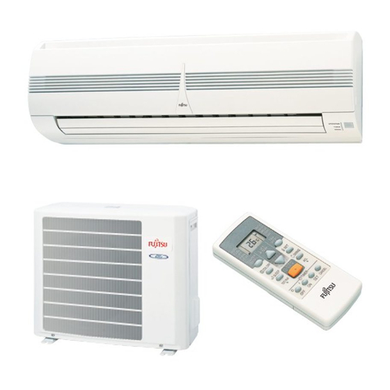
SPLIT TYPE ROOM
AIR CONDITIONER
WALL MOUNTED
Models
Indoor unit
ASY9USCCW
ASY9USCCW
ASY12USCCW
CONTENTS
SPECIFICATIONS . . . . . . . . . . . . . . . . . .
OUTLINE AND DIMENSIONS . . . . . . . . .
CIRCUIT DIAGRAM . . . . . . . . . . . . . . . . .
INDOOR PCB CIRCUIT DIAGRAM . . . . .
ERROR CONTENTS . . . . . . . . . . . . . . . . 8
DISASSEMBLY ILLUSTRATION . . . . . . .
PARTS LIST . . . . . . . . . . . . . . . . . . . . . .
STANDARD ACCESSORIES . . . . . . . . .16
type
Outdoor unit
AOY9USCC
AOY9UFCC
AOY12USCC
1
2
4
5
7
9
14
Advertisement
Table of Contents


Need help?
Do you have a question about the ASY9USCCW and is the answer not in the manual?
Questions and answers