
Related Manuals for FLOWTECH flowboost F.V


Summary of Contents for FLOWTECH flowboost F.V
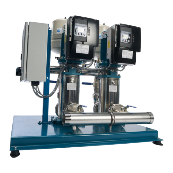
- Page 1 F.V Pump Manual OPERATION AND MAINTENANCE MANUAL First Publication Date: 01/09/2020 Revision: Revision Date:...
-
Page 2: Table Of Contents
OPERATION & MAINTENANCE CONTENTS General Information Safety Information Safety Warnings & Precautions Customer / Contractor Responsibilities Technical Information Intended use Improper use Marking Technical data Rated motor power Operating conditions General provisions Handling Installation Dimensions Pipes Electrical connection Electrical diagram Start-up and Operation First starting Starting and checking operations... -
Page 3: General Information
General Information These instructions are to assist in the installation of the flowboost F.V Pump please follow them carefully. If, having read this Operation & Maintenance Manual, there is any doubt about any aspect of the installation please don't hesitate to contact our technical team. -
Page 4: Safety Information
Water Solutions. This document is intended for ALL installers, operators, users and persons carrying out maintenance of this equipment and must be kept with the equipment, for the life of the equipment and made available to all persons at all times. -
Page 5: Safety Warnings & Precautions
Safety Warnings & Precautions These instructions should be read and clearly understood before working on the system. Please read this manual carefully and all of the warning signs attached before installing or operating the equipment keep this manual handy for your reference. This equipment should be installed, adjusted and serviced by trained and qualified personnel. -
Page 6: Customer / Contractor Responsibilities
exclamat CAUTION! - It is strongly recommended that all electrical equipment conforms to National Electrical Codes and local regulations. Only qualified personnel should perform installation, alignment and maintenance. The manufacturer reserves the right to alter the technical data in order to make improvements or update information. exclamat CAUTION! - Failure to observe these rules will render the guarantee invalid. -
Page 7: Technical Information
Improper use of the product reduces the safety and the efficiency of the device, Flowtech shall not be responsible for failure or accident due to improper use. Do not use in ponds, tanks or swimming pools or where people may enter or come into contact with the water. -
Page 8: Rated Motor Power
Follow the routine maintenance schedules and the promptly replace damaged parts, this will allows the device to work in the best conditions. Use only original spare parts provided from Flowtech. Don’t remove or change the labels placed on the device. -
Page 9: Handling
Transportation The product is packed to maintain the content intact. During transportation avoid to stack excessive weights. Ensure that during the transportation the box cannot move. It is not necessary to use any special vehicle to transport the packaged device. The transport vehicles must comply, for the weight and dimensions, with the chosen product (see technical catalogue dimensions and weights). -
Page 10: Pipes
Installation The standard version pumps must be installed with the rotor axis in the vertical position and with the base under the pump. The 50, 65 and 80 models can be installed in horizontal position, using the appropriate support feet, which are supplied on request. - Page 11 Ensure the internal pipe surface is clean before connection. Secure all pipes to their rests close to the pump and connect them so that they are not subjected to stress and do not transmit vibration or flexion strain to the pump (see fig.3). Provide for the possibility of draining the pump without having to drain the entire system.
-
Page 12: Electrical Connection
Electrical connection Electrical connection must be carried out only by a qualified electrician in accordance with local regulations. Follow all safety standards. The unit must be properly earthed (grounded). Connect the earthing (grounding) conductor to the terminal with the marking. Compare the frequency and mains voltage with the name-plate data and connect the supply conductors to the terminals in accordance with the appropriate diagram inside the terminal box cover. -
Page 13: Start-Up And Operation
Start-up and Operation Preliminary checks before start-up of the pump Do not start-up the device in case of damaged parts. Make sure the coupling with the pump shaft turns freely when rotated by hand. Make sure the screws of the coupling are tightened. Make sure the coupling guard is fastened on the lantern bracket. -
Page 14: Starting And Checking Operations
When the liquid level on the suction side is above the pump (inflow under positive suction head, fig. 3B), fill the pump by slowly and completely opening the inflow gate valve while keeping the delivery gate valve and air vent holes open to release the air. During filling, keep the air vent holes open only if the inflowing liquid presents no possible danger on account of its nature, temperature or pressure. -
Page 15: Maintenance
Maintenance operations that are not described in this manual must be made only by special personnel authorized by Flowtech. Routine maintenance Before every maintenance operations disconnect the power supply and make sure that the device could not accidentally operate. -
Page 16: Dismantling The System
Dismantling the system Close the suction and delivery gate valves and drain the pump casing before dismantling the pump. Dismantling the pump Before dismantling, disconnect the power cable from the terminal box, close the gate valves in the suction and delivery pipes and empty the pump casing (fig. 4). For dismantling and re-assembly refer to the drawing. -
Page 17: Remounting
Remounting To remount the components follow the dismantling procedure in inverse order. Check the state of the O-rings and replace them if they are damaged. Make sure that the O-rings are correctly inserted on their seats on the pump casing and upper cover. Lubricate the seal rings with clean water or any other compatible lubricant. -
Page 18: Disposal
Disposal European Directive 2012/19/EU (WEEE) The final disposal of the device must be done by specialized company. Make sure the specialized company follows the classification of the material parts for the separation. Observe the local regulations and dispose the device accordingly with the international rules for environment protection. - Page 19 Pump blocked 2a. Prolonged periods of 2a. Rotation may be started directly from the pump shaft inactivity with formation or from the joint (remember to turn off the electricity of rust inside the pump supply first ) or contact an authorised service centre 2b.
- Page 20 Noise and vibrations 5a. Rotating part 5a. Check that no solid bodies are obstructing the rotor from the pump unbalanced 5b. Worn bearings 5b. Replace the bearings 5c. Pump and pipes not 5c. Anchor the delivery and suction piping as needed firmly attached 5d.
- Page 21 Unit 1 Lock Flight Buildings, Wheatlea Industrial Estate, Wigan, Greater Manchester WN3 6XP United Kingdom 9001 : 2015 REGISTERED Membership No. 700106 Certificate No. 185352020 Copyright © 2020 • All Rights Reserved • Flowtech Water Solutions Limited • Company Number: 05125479 • VAT Number: 836 8024 19...
Need help?
Do you have a question about the flowboost F.V and is the answer not in the manual?
Questions and answers