
Subscribe to Our Youtube Channel
Related Manuals for FLOWTECH flowboost G.V


Summary of Contents for FLOWTECH flowboost G.V
- Page 1 G.V Pump Manual OPERATION AND MAINTENANCE MANUAL First Publication Date: 01/09/2020 Revision: Revision Date:...
- Page 2 General Information These instructions are to assist in the installation of the flowboost G.V Pump please follow them carefully. If, having read this Operation & Maintenance Manual, there is any doubt about any aspect of the installation please don't hesitate to contact our technical team.
- Page 3 Water Solutions. This document is intended for ALL installers, operators, users and persons carrying out maintenance of this equipment and must be kept with the equipment, for the life of the equipment and made available to all persons at all times.
-
Page 4: Safety Warnings
Safety Warnings & Precautions These instructions should be read and clearly understood before working on the system. Please read this manual carefully and all of the warning signs attached before installing or operating the equipment keep this manual handy for your reference. This equipment should be installed, adjusted and serviced by trained and qualified personnel. - Page 5 exclamat CAUTION! - It is strongly recommended that all electrical equipment conforms to National Electrical Codes and local regulations. Only qualified personnel should perform installation, alignment and maintenance. The manufacturer reserves the right to alter the technical data in order to make improvements or update information. exclamat CAUTION! - Failure to observe these rules will render the guarantee invalid.
-
Page 6: Protecting The Environment
Clean-up of spills. Exceptional sites Radiation Hazard Do NOT send the product to Flowtech Water Solutions if it has been exposed to nuclear radiation, unless Flowtech Water Solutions has been informed and appropriate actions have been agreed upon. Recycling guidelines Always follow local laws and regulations regarding recycling. -
Page 7: Inspect The Unit
Inspect the unit Remove packing materials from the product. Dispose of all packing materials in accordance with local regulations. Inspect the product to determine if any parts have been damaged or are missing. If applicable, unfasten the product by removing any screws, bolts, or straps. For your personal safety, be careful when you handle nails and straps. -
Page 8: Product Description
Product Description Figure 2 and Figure 3 show a typical single-pump and multi-pump system using the unit. When the system is connected directly to the water supply use a low-pressure switch on the suction side. Figure 2: Single-pump system Figure 3: Multi-pump system Pump with e-SM Motor Drive Diaphragm pressure tank Distribution panel... - Page 9 Pressure tank A diaphragm pressure tank is used on the discharge side of the pump to maintain pressure in the pipes when there is no water demand. The unit stops the pump from continuing to run at zero demand and reduce the size of the tank that is required for supply purposes.
- Page 10 Booster unit technical data Table 1: Electrical, Environmetal and Installation specifications Booster model Control panel supply (see to idetification code) Input Input frequency [Hz] ± 50/60 Main supply L1 L2 Nominal input voltage [V] ± ± ± Max. input current continuous [A] See rating plate on electric panel Max control panel power [kW] See rating plate on electric panel...
-
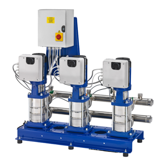
Page 11: Dimensions And Weights
Dimensions and weights Design and layout Booster unit parts and description as standards configuration Figure 6: Booster unit Position Description number Control Panel Electric pump E (e-SM drive) series Baseplate Priming connection Damper Suction manifold Suction on-off valve Non-return valve Delivery on-off valve Pressure transmitter Pressure gauge... -
Page 12: Mechanical Installation
Mechanical Installation Installation site checklist Never install the unit in an explosive or flammable environment. Always refer to the local and national regulations, legislation, and codes in force regarding selection of installation site, and water and power connections. Keep the manual, drawings, and diagrams accessible for detailed installation and operation instructions. It is important that the manual is available for equipment operators. -
Page 13: Outdoor Installation
Figure 7: Unit installation Protection against dry running The standard electric panel is ready for connection of a common float switch applicable for open tanks or a minimum pressure switch on the suction side (recommended value 0.2÷0.4 bar). When the minimum pressure conditions are restored, the pumps start up automatically. -
Page 14: Electrical Installation
Electrical Installation EQUIPMENT HAZARD. Rotating shafts and electrical equipment can be hazardous. All electrical work must conform to national and local electrical codes. Installation, start-up, and maintenance must be performed by trained and qualified personnel. Failure to follow these guidelines could result in death or serious injury. All electrical wiring must be carried out by an authorized electrician, in accordance with the electrical regulations locally in force. -
Page 15: Operation
Grounding (earthing) Always connect the external protection conductor to ground (earth) terminal before making other electrical connections. All electrical equipment must be ground (earth) connected. This applies to the pump unit and related equipment. Verify the pump ground terminal is earthed. Keep the ground wire connections as short as possible. - Page 16 Table 2: Wait times e-SM Drive model Minimum waiting times [min] 103, 105, 107, 111, 115 303, 305, 307, 311, 315, Start or stop the unit The starting and stopping of the pumps are determined based on the unit to be controlled (pressure, level) settings of the controller.
-
Page 17: Maintenance
To ensure its proper operation, the diaphragm pressure tank must be precharged to 0.9 x adjustment pressure value. The precharge operation must be performed with the tank empty. Startup To start the set, proceed as follows: Connect the water supply. Connect the power supply. -
Page 18: Troubleshooting
Troubleshooting The maintenance and repair operations must be performed by qualified personnel. Before servicing the set, disconnect the power supply and make sure there is no pressure in the hydraulic components. Wait at least 4 min before starting work on or in the unit. The capacitors in the intermediate circuit are discharged by the internal discharge resistors. - Page 19 Pump leaks water Cause Solution Defective mechanical seal Replace the mechanical seal Undue mechanical stress on pump Support the pipes Too noisy Cause Solution Water return when pumps stop Check the non-return valve Cavitation Check suction Pump rotation hindered Check for undue mechanical stress on pump The unit does not generate the desiderate pressure Cause Solution...
- Page 20 Pump runs at maximum speed without stops Cause Solution Pressure set point not suitable for Set new set point in according to pump performance the system (the value is higher than the pump is able to deliver) Sensor is not connected or damaged Check the hydraulic and electrical connection of sensor Only one pump is operating Cause...
-
Page 21: Service And Maintenance
Unit 1 Lock Flight Buildings, Wheatlea Industrial Estate, Wigan, Greater Manchester WN3 6XP United Kingdom 9001 : 2015 REGISTERED Membership No. 700106 Certificate No. 185352020 Copyright © 2020 • All Rights Reserved • Flowtech Water Solutions Limited • Company Number: 05125479 • VAT Number: 836 8024 19...
Need help?
Do you have a question about the flowboost G.V and is the answer not in the manual?
Questions and answers