
Related Manuals for saro MINI-COLD ROOM 100


Summary of Contents for saro MINI-COLD ROOM 100
- Page 1 MINI-COLD ROOM 100 ® COLD AND FREEZER ROOMS TRANSLATION OF THE ORIGINAL INSTRUCTIONS Revision 00 - 02/2023 USE AND MAINTENANCE MANUAL...
-
Page 3: Table Of Contents
USE AND MAINTENANCE MANUAL MINI-COLD ROOM 100 TABLE OF CONTENTS TABLE OF CONTENTS ......... 3 7. CONTROL PANEL ......25 7.1. CONTROL PANEL (mod. EW961 - EW974)..25 TECHNICAL DATA SHEETS ......5 7.1.1. Display ............26 USE AND MAINTENANCE MANUAL ..... 7 7.2. - Page 4 MINI-COLD ROOM 100...
-
Page 5: Technical Data Sheets
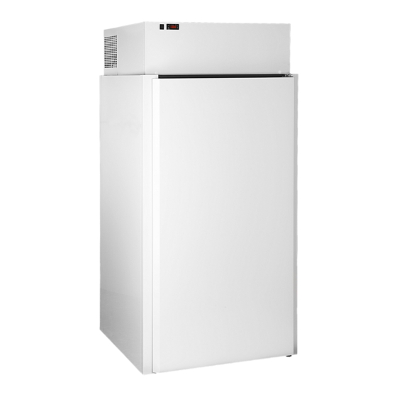
USE AND MAINTENANCE MANUAL MINI-COLD ROOM 100 TECHNICAL DATA SHEETS... - Page 6 MINI-COLD ROOM 100 MINI-COLD ROOM 100 Cold and freezer room, insulation thickness 60 mm SUITABLE TO STORE MEAT CURED MEATS FROZEN GOODS DAIRY PRODUCTS* PASTRIES FISH* FRUITS AND VEGETABLES *Only with stainless steel interior fittings and without floor in the TN version.
-
Page 7: Use And Maintenance Manual
USE AND MAINTENANCE MANUAL MINI-COLD ROOM 100 USE AND MAINTENANCE MANUAL... -
Page 8: General Preliminary Information
Carefully read this manual before carrying out installation, maintenance and/or before using the equipment. This manual is attached to the equipment MINI-COLD ROOM 100. The Manufacturer is not liable for breakages, accidents or various problems due to non-compliance with and in any case the non-application of the provisions contained in this manual. -
Page 9: Regulatory Framework
USE AND MAINTENANCE MANUAL MINI-COLD ROOM 100 1.4. REGULATORY FRAMEWORK The equipment is designed according to the regulatory framework described in the accompanying declaration of conformity and the identification plate placed on the same, as well as the requirements, which can be downloaded directly from the manufacturer’s website. -
Page 10: Safety Warnings
MINI-COLD ROOM 100 SAFETY WARNINGS The Manufacturer cannot be held liable for any damage, suffered by people or things, caused by non-compliance with the aforementioned requirements or deriving from tampering with even a single part of the equipment and from the use of non-original spare parts. -
Page 11: Obligations And Prohibitions
USE AND MAINTENANCE MANUAL MINI-COLD ROOM 100 2.1. OBLIGATIONS AND PROHIBITIONS 2.1.1. OBLIGATIONS ▪ Only qualified technical personnel should perform the installation work (see chapter 'INSTALLATION') ▪ Keep the area around the equipment free and clean ▪ Keep the entire perimeter of the equipment free so that there is air circulation ▪... -
Page 12: Identification And Description
MINI-COLD ROOM 100 IDENTIFICATION AND DESCRIPTION 3.1. EQUIPMENT IDENTIFICATION The nameplate is on the side of the equipment. Contains: ▪ Serial number ▪ The type/functional features ▪ The details of the certification and marking. Do not remove the identification plate and/or replace it with other plates. -
Page 13: Intended Use
USE AND MAINTENANCE MANUAL MINI-COLD ROOM 100 3.2. INTENDED USE The equipment is a COLD AND FREEZER ROOM for professional use. Used to store packaged and/or unpackaged food. The Manufacturer cannot be held liable for uses other than those indicated. -
Page 14: Main Components
MINI-COLD ROOM 100 3.4. MAIN COMPONENTS POS. ELEMENT NOTES PANEL STRUCTURE CONTROL PANEL BLIND PAD DOOR WITH MAGNETIC CLOSURE SHELF DOOR GASKET Including: ▪ BUILT-IN MONOBLOCK REFRIGERATION UNIT Evaporator ▪ Condenser ELECTRICAL RESISTANCE Heating cable In the case of purchasing equipment without a built-in monoblock refrigeration unit, there is the set-up for connection to the remote unit. -
Page 15: Receipt And Handling
USE AND MAINTENANCE MANUAL MINI-COLD ROOM 100 RECEIPT AND HANDLING 4.1. EQUIPMENT RECEIPT The equipment can be delivered: ▪ Assembled / Disassembled with built-in monoblock refrigeration unit ▪ Without built-in monoblock refrigeration unit (with set up for connection to remote unit). -
Page 16: Packaging Removal And Inspection
MINI-COLD ROOM 100 4.1.2. PACKAGING REMOVAL AND INSPECTION For the removal of the packaging: STEP ACTION PICTURE Remove the straps. Remove the packaging cardboard. Lift the equipment to remove it from the pallet. Place the equipment in its designated place. -
Page 17: Packaging Disposal
USE AND MAINTENANCE MANUAL MINI-COLD ROOM 100 4.1.3. PACKAGING DISPOSAL The materials used for packaging are recyclable and must be collected. Separate the various packaging materials and dispose of them in accordance with the regulations in force in the country of installation. -
Page 18: Installation
MINI-COLD ROOM 100 INSTALLATION Only qualified technical personnel should perform installation operations on the equipment. CAUTION Do not install and use the equipment in ATEX classified environments, locations or areas. The manufacturer accepts no liability in the event of non-compliance with current safety regulations. -
Page 19: Minimum Safety Distances
USE AND MAINTENANCE MANUAL MINI-COLD ROOM 100 Do not obstruct the supply and return air ventilation openings in the equipment. Place the equipment away from heat sources and open flames. 5.1.1.1. LOCAL FEATURES FOR REMOTE UNIT INSTALLATION In the case of purchasing equipment without a built-in monoblock refrigeration unit, there is the set-up for connection to the remote unit. -
Page 20: Cold Room Assembly
MINI-COLD ROOM 100 5.2. COLD ROOM ASSEMBLY Use personal protective equipment PPE and provisional works during installation. Two operators are required to assemble the equipment. Use the enclosed spanner to mount the equipment. For the assembly of the structure: STEP... - Page 21 USE AND MAINTENANCE MANUAL MINI-COLD ROOM 100 STEP ACTION PICTURE Fasten the door panel (D ) to the hooks on the outside of the floor panel. Note: tilt the equipment to perform this operation. Fasten the ceiling panel by means of the hooks inside the cold room.
-
Page 22: Assembly Of Shelves
Togliere l’imballo in cartone; Sganciare le protezioni in plastica dei piedini; MINI-COLD ROOM 100 STEP ACTION PICTURE Remove the protective films present to protect the steel (both external and internal). Place the end caps at the holes. Rimuovere il supporto in legno antiurto;... -
Page 23: Mounting The Hooks
USE AND MAINTENANCE MANUAL MINI-COLD ROOM 100 5.2.2. MOUNTING THE HOOKS For the mounting of the hooks: STEP ACTION PICTURE Insert one end of the hooks (A) into a hole in the side panel. Insert the opposite end into the hole of the opposite side panel. -
Page 24: Connections
MINI-COLD ROOM 100 CONNECTIONS 6.1. ELECTRICAL CONNECTION Only qualified technical personnel should perform connection operations on the equipment. The electrical connection must be carried out in accordance with the legal compendium and regulations applicable in the country where the equipment is installed. -
Page 25: Control Panel
USE AND MAINTENANCE MANUAL MINI-COLD ROOM 100 CONTROL PANEL 7.1. CONTROL PANEL (MOD. EW961 - EW974) POS. ICON ELEMENT DESCRIPTION ▪ Set to “0”: machine switched off MAIN SWITCH 0/I ▪ Set to “I”: machine electrically powered. DISPLAY Displays the equipment operating parameters. -
Page 26: Display
MINI-COLD ROOM 100 7.1.1. DISPLAY POS. ICON ELEMENT DESCRIPTION DISPLAY ▪ Flashing: reduced set active Reduced SET / SET ▪ Quick flash.: access to level 2 parameters ▪ Off: LED off in all other cases ▪ Fixed on: compressor on ▪... -
Page 27: Access And Use Of The Menu
USE AND MAINTENANCE MANUAL MINI-COLD ROOM 100 7.2. ACCESS AND USE OF THE MENU The resources are organised in two menus: ▪ Machine Status Menu ▪ Programming Menu Press the button once to confirm the last value shown on the display and return to the previous display. Inactivity of the keyboard for more than 15 seconds (time-out) also confirms the last displayed value and a return to the previous display. -
Page 28: Setpoint Modification Block
MINI-COLD ROOM 100 7.2.3. SETPOINT MODIFICATION BLOCK The equipment provides the option to disable keyboard operation. The keyboard can be locked by programming the “LOC” parameter. If the keyboard is locked, it is always possible to access the Machine Status menu by pressing the key and display the Setpoint, however its value cannot be changed. -
Page 29: Use
USE AND MAINTENANCE MANUAL MINI-COLD ROOM 100 Before using the equipment, check that it is in perfect condition. In the presence of faults, the equipment must be decommissioned and the Technical Assistance Service must be contacted. CAUTION Keep all the supply and return air ventilation openings inside the equipment free of obstructions. -
Page 30: Product Loading
MINI-COLD ROOM 100 8.3. PRODUCT LOADING Load a maximum of 25 kg on each shelf. The load must be evenly distributed on the shelf. For proper storage, do not introduce hot products. Wait for the product to cool down before placing it inside the equipment. -
Page 31: Manual Defrost
USE AND MAINTENANCE MANUAL MINI-COLD ROOM 100 8.4.2. MANUAL DEFROST A manual defrost can be performed if required. Perform defrosting with door open or door closed. In the case of defrosting with the door closed, the time required will be longer. -
Page 32: Cleaning
MINI-COLD ROOM 100 CLEANING 9.1. SAFETY WARNINGS FOR CLEANING WARNING Electrical hazard. Disconnect the power supply before cleaning. WARNING Electrical hazard. Do not use water jets and/or high-pressure lances to wash the internal and external parts of the equipment. WARNING Do not damage the refrigerant fluid circuit. -
Page 33: Table Of Cleaning Operations
USE AND MAINTENANCE MANUAL MINI-COLD ROOM 100 9.2. TABLE OF CLEANING OPERATIONS The following table lists a series of cleaning operations to be carried out according to the recommended frequency. FREQUENCY OPERATION DAILY WEEKLY MONTHLY EVERY 6 YEARLY MONTHS ■... -
Page 34: Maintenance
MINI-COLD ROOM 100 MAINTENANCE WARNING Electrical hazard. Disconnect the power supply before carrying out maintenance work. CAUTION The ceiling panel cannot be walked on except for maintenance. Only one person with a maximum weight of 80 kg is permitted. Only authorised technical personnel should service the equipment. -
Page 35: Extraordinary Maintenance
USE AND MAINTENANCE MANUAL MINI-COLD ROOM 100 10.2. EXTRAORDINARY MAINTENANCE Extraordinary maintenance includes service, repair, and restoration of nominal operating conditions or replacement of a faulty, defective or worn component. 10.2.1. REPLACEMENT OF MOTOR FAN For replacement, contact the Authorised Dealer or Service Centre. -
Page 36: Diagnostics
MINI-COLD ROOM 100 DIAGNOSTICS 11.1. ALARMS LABEL FAULT CAUSE EFFECTS TROUBLESHOOTING ▪ Display of the E1 label ▪ ▪ Reading of values Fixed Alarm Icon outside the operating ▪ Disabling of the maximum and ▪ Check the probe type (NTC) Probe1 faulty ▪... -
Page 37: Decommissioning And Disposal
USE AND MAINTENANCE MANUAL MINI-COLD ROOM 100 DECOMMISSIONING AND DISPOSAL 12.1. LONG PERIODS OF INACTIVITY If the equipment is not used for a long period of time (more than 2-3 weeks): STEP ACTION Disconnect the power supply. Carry out a thorough cleaning of the equipment (see chapter 'CLEANING'). -
Page 38: Attachments
MINI-COLD ROOM 100 ATTACHMENTS 13.1. WIRING DIAGRAM EQUIPMENT WIRING DIAGRAM CODE MINI-COLD ROOM 100 TN EL_MB_MIC_TN_001 MINI-COLD ROOM 100 BT EL_MB_MIC_BT_003... - Page 39 USE AND MAINTENANCE MANUAL MINI-COLD ROOM 100...
- Page 40 MINI-COLD ROOM 100...
-
Page 41: Control Panel Parameter Table
USE AND MAINTENANCE MANUAL MINI-COLD ROOM 100 13.2. CONTROL PANEL PARAMETER TABLE PARAMETER MACHINE DESCRIPTION OPERATOR SEtpoint for temperature control. COMPRESSOR diFferential. Compressor relay tripping differential: the compressor stops on reaching the 1&2 Setpoint value set (as indicated by the adjustment probe), and restarts at temperature value equal to the Setpoint plus the value of the differential. - Page 42 MINI-COLD ROOM 100 PARAMETER MACHINE DESCRIPTION OPERATOR delay Output (from power) On. Output activation delay time from instrument switch-on or OdO (!) after a power failure. DEFROSTING "defrost type. Type of defrosting. 0 = electrical defrosting - compressor off (OFF) during defrosting;' 1&2...
- Page 43 USE AND MAINTENANCE MANUAL MINI-COLD ROOM 100 PARAMETER MACHINE DESCRIPTION OPERATOR ALARMS Allows you to select whether the HAL and LAL parameters will have absolute (Att=0) or relative (Att=1) values. Alarm Fan differential. Alarms differential. Higher ALarm. Maximum temperature alarm. Temperature value (in relative value), the 1&2...
- Page 44 MINI-COLD ROOM 100 PARAMETER MACHINE DESCRIPTION OPERATOR Defrost display lock. Viewing mode during defrosting. 0 = shows the temperature read by the room probe; 1 = locks the reading on the temperature value read by room probe when defrosting starts, 1&2...
Need help?
Do you have a question about the MINI-COLD ROOM 100 and is the answer not in the manual?
Questions and answers